Stuart Twin Victoria (Princess Royal) Mill Engine
Discussion


Hi there it looks to be coming along nicely and as it runs in it should settle down nicely.
Be careful of lapping (choice of lapping compound especially) the bushings as the grits may imbed in the bushing giving an undesired effect when running.
I would not be to worried about some of the comments on the ME forum. Almost all are made in a effort to pass on some form of help, but i feel some on the forum are regimented into the way they were taught themselves and don't see that there are always more than one way to acomplish a job, despite them having many years of machining expirience. Some of the more experienced people there, have a selection of tools assembled over a lifetime of machining, the likes of which us mear mortals would only dream of and so they sometimes forget we dont have the same selection to draw on.
At the end of the day its your project and you make it how you want to and enjoy the process as its supposed to be about enjoyment not a chore of work, like that Aero Vulcan!
rolster said:
Hi there it looks to be coming along nicely and as it runs in it should settle down nicely.
Be careful of lapping (choice of lapping compound especially) the bushings as the grits may imbed in the bushing giving an undesired effect when running.
I would not be to worried about some of the comments on the ME forum. Almost all are made in a effort to pass on some form of help, but i feel some on the forum are regimented into the way they were taught themselves and don't see that there are always more than one way to acomplish a job, despite them having many years of machining expirience. Some of the more experienced people there, have a selection of tools assembled over a lifetime of machining, the likes of which us mear mortals would only dream of and so they sometimes forget we dont have the same selection to draw on.
At the end of the day its your project and you make it how you want to and enjoy the process as its supposed to be about enjoyment not a chore of work, like that Aero Vulcan!
Thanks Rolster. Yes, all good, the shaft machining worked in the end. I asked a couple of other machinists at work, and that said they’d do it like I did, so I’m fine with it.Be careful of lapping (choice of lapping compound especially) the bushings as the grits may imbed in the bushing giving an undesired effect when running.
I would not be to worried about some of the comments on the ME forum. Almost all are made in a effort to pass on some form of help, but i feel some on the forum are regimented into the way they were taught themselves and don't see that there are always more than one way to acomplish a job, despite them having many years of machining expirience. Some of the more experienced people there, have a selection of tools assembled over a lifetime of machining, the likes of which us mear mortals would only dream of and so they sometimes forget we dont have the same selection to draw on.
At the end of the day its your project and you make it how you want to and enjoy the process as its supposed to be about enjoyment not a chore of work, like that Aero Vulcan!
For lapping I think Autosol and oil would be enough. I’m going to leave that until the whole thing is set up on its base so that it’ll lap in when it’s in its final alignment.
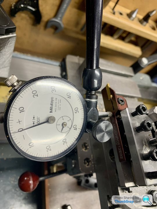
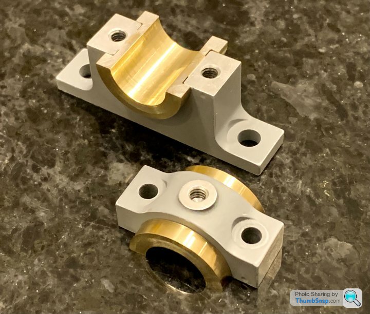
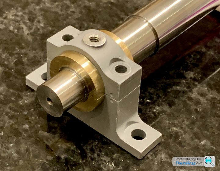
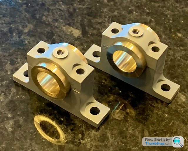
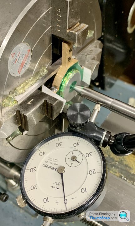
I was pondering why the brass bearings had been so easy to turn to be a perfect fit, simultaneously in both the housings and to the shaft, as well as side-to-side in the housings. With my skills I knew it was very unlikely to achieve such a good fit straight away.
After some measurement I found that the o/d of the bearing groove was smaller than the I/d of the housing, yet it seemed a great fit, with no play either up or down or side-to-side.
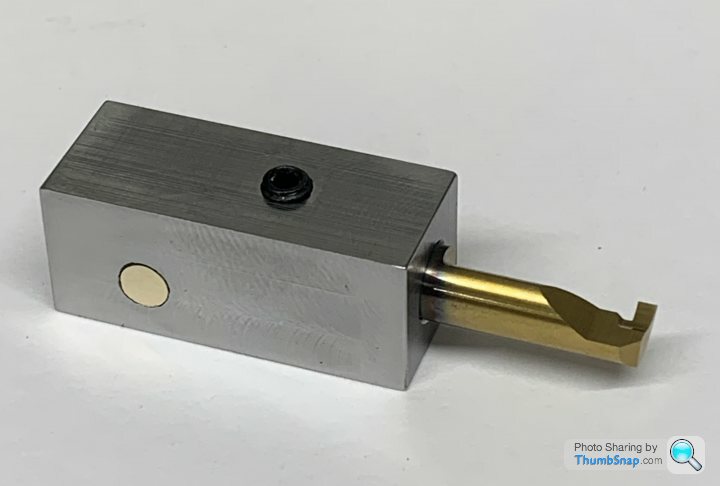
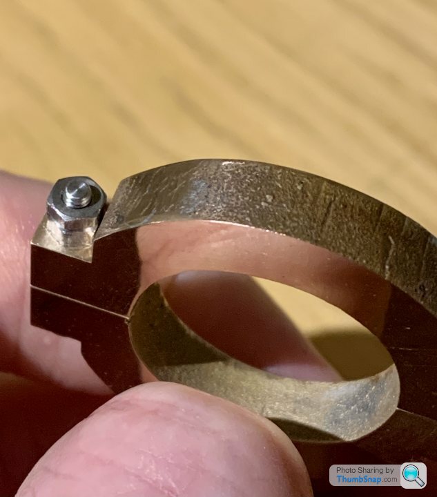
Careful examination revealed the inevitable error: the parting tool I used for grooving had been ground to a slight taper, and therefore the insides of the groove flanges were also tapered. So when the bearings were ‘near enough’, light pressure deformed the housings enough to give the impression of a perfect, snug fit:
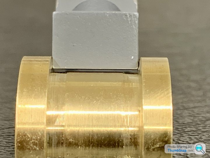
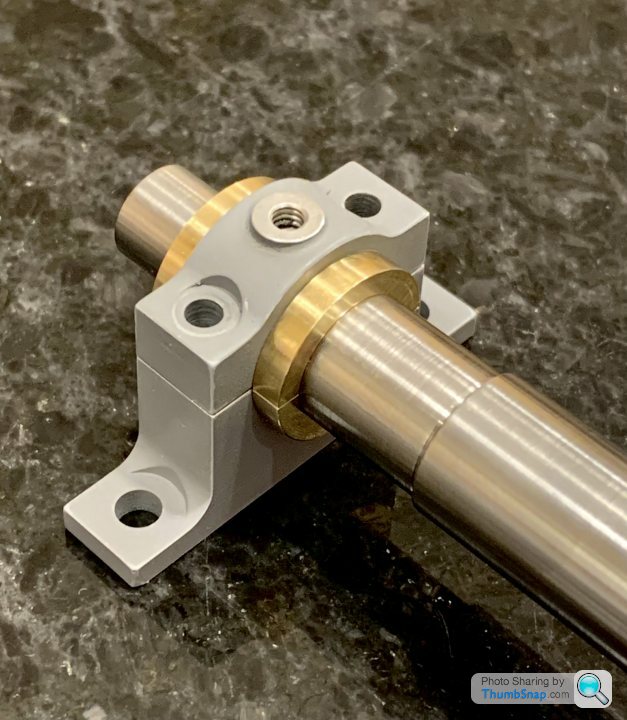
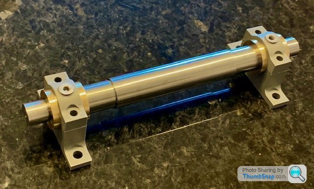
However, pressing the bearings fully home with a plastic pen showed the true situation - a gap, and a loose fit to the shaft:
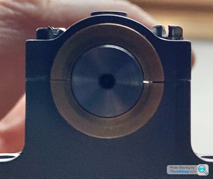
Of course all might be well initially, but any radial load on the shaft (e.g. imperfect flywheel/crankshaft balance) would eventually displace a bearing, with a resulting death rattle on the engine.
Metal shims are out, due to oil needing to flow vertically into the top bearing half with no leakage path between the bearing and housing. Liquid shim is ruled out because it has no place in a precision bearing fit on a steam engine. So unfortunately the only remedy is to scrap all the bearings and start all over again from raw square brass bar as per 28th August.
Lesson learned: check equipment, and for me - stick with my rule of never using HSS tools unless there’s no other option.
After some measurement I found that the o/d of the bearing groove was smaller than the I/d of the housing, yet it seemed a great fit, with no play either up or down or side-to-side.
Careful examination revealed the inevitable error: the parting tool I used for grooving had been ground to a slight taper, and therefore the insides of the groove flanges were also tapered. So when the bearings were ‘near enough’, light pressure deformed the housings enough to give the impression of a perfect, snug fit:
However, pressing the bearings fully home with a plastic pen showed the true situation - a gap, and a loose fit to the shaft:
Of course all might be well initially, but any radial load on the shaft (e.g. imperfect flywheel/crankshaft balance) would eventually displace a bearing, with a resulting death rattle on the engine.
Metal shims are out, due to oil needing to flow vertically into the top bearing half with no leakage path between the bearing and housing. Liquid shim is ruled out because it has no place in a precision bearing fit on a steam engine. So unfortunately the only remedy is to scrap all the bearings and start all over again from raw square brass bar as per 28th August.
Lesson learned: check equipment, and for me - stick with my rule of never using HSS tools unless there’s no other option.
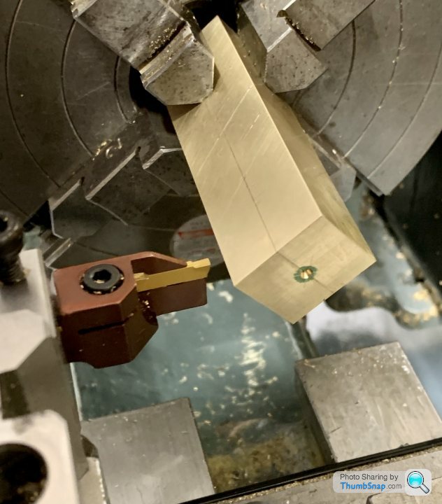
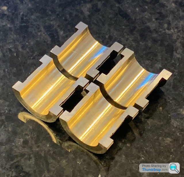
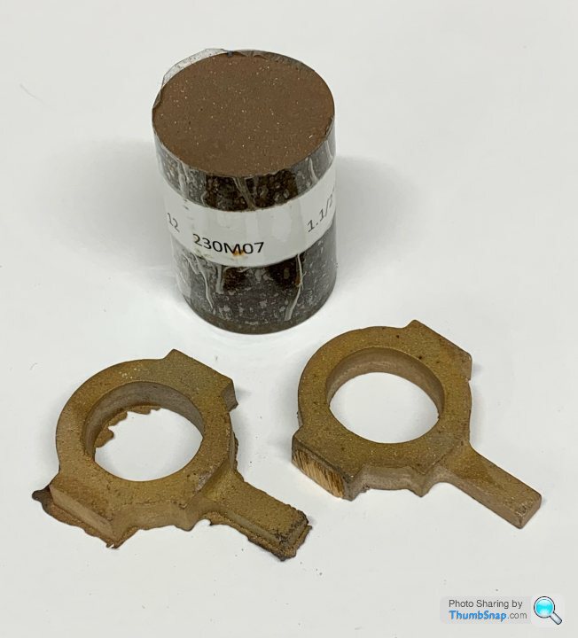
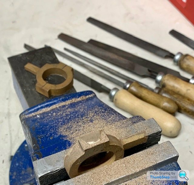
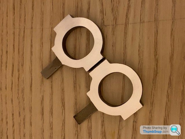
So after getting a bit demoralised over the bearing error after all that work (about 6 months ago - time flies) this evening I started again from scratch: cut the new brass bar to approximate size with the hacksaw:
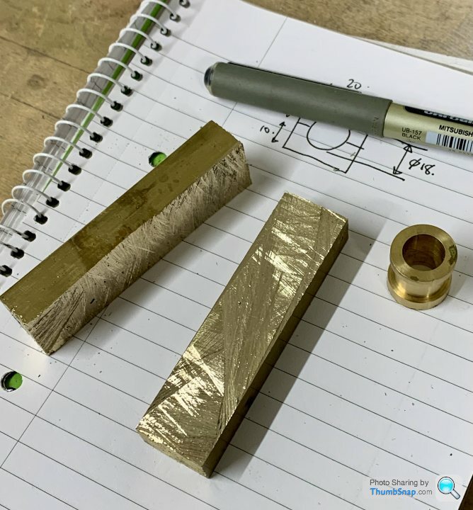
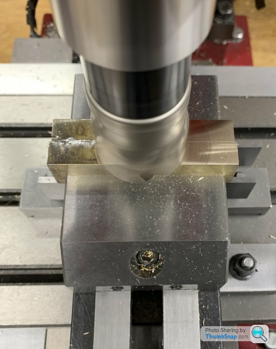
Then milled the mating faces and their opposites to the same thickness:
Now ready to solder together again, then final milling of the flanks and ends:
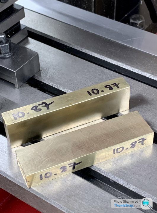
Hopefully I can get the solder to work a bit better this time too.
Then milled the mating faces and their opposites to the same thickness:
Now ready to solder together again, then final milling of the flanks and ends:
Hopefully I can get the solder to work a bit better this time too.

So, deep breath, and try again…
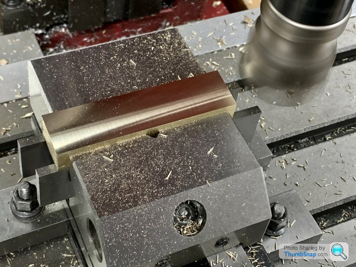
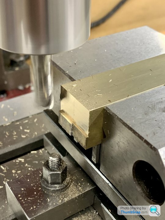
I cut the block in half to stiffen everything up:
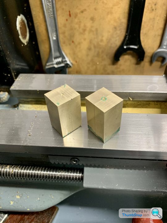
Faced:
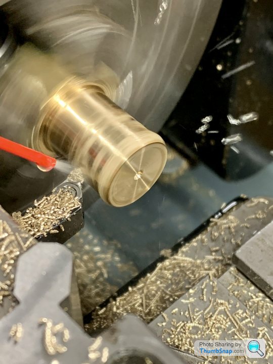
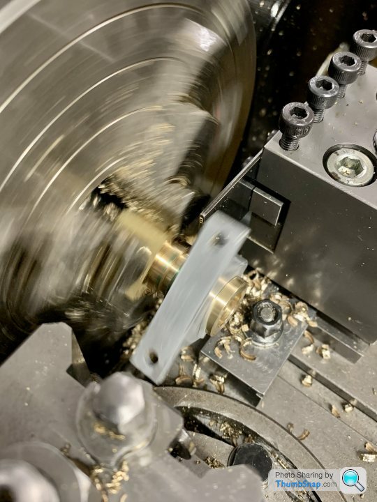
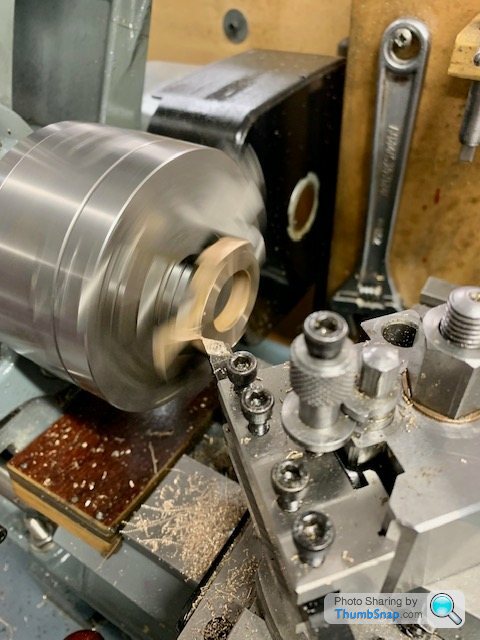
Flange O/D turned from square:
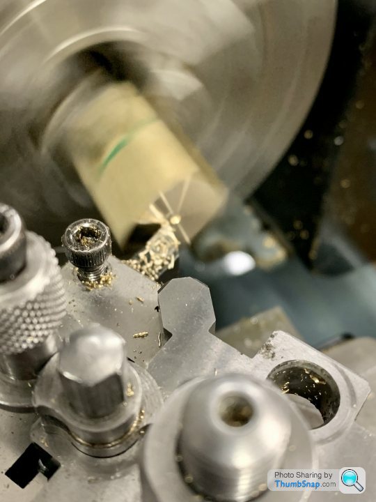
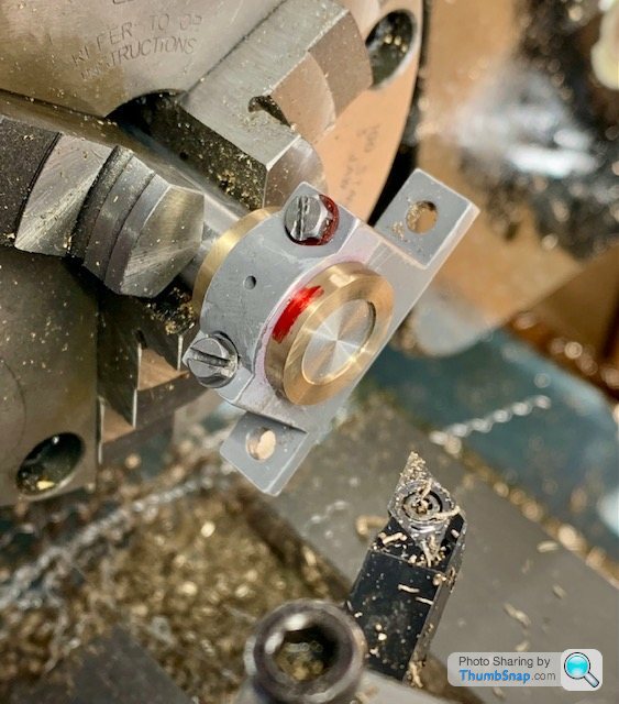
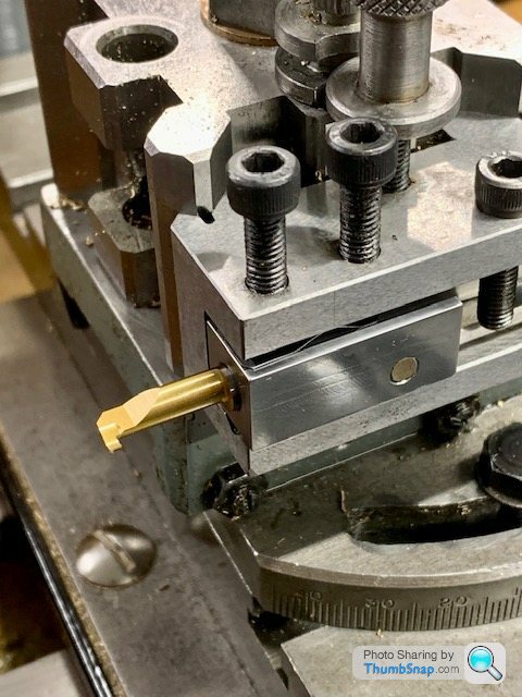
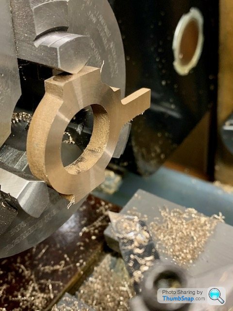
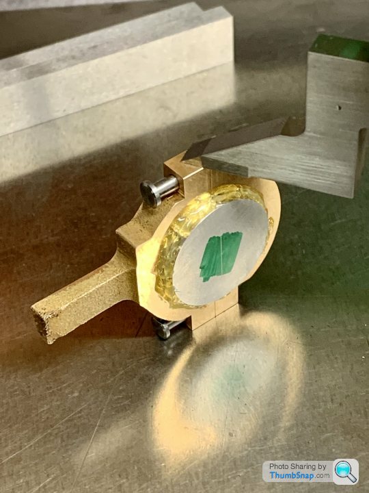
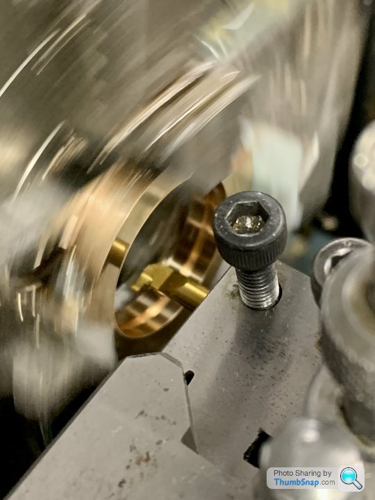
Set the grooving tool normal:
I had to use back-gear to avoid chatter, but all ok. The recess was by far the hardest part. Once again I found it difficult to judge dimensions and simultaneously machine a width and diameter without going over or undersize on one or the other. Having the saddle stop at one end was fine, but it’s fresh air at the other end, and very easy to go too far in the width while getting the diameter. What I did was get the width right, then when the diameter was almost there, undersize each end to avoid the pedestal radii. This left a raised block in the middle, and I changed tools to a normal turning tool to reduce that until it was the perfect diameter to match the housing. All a bit sketchy I think, but it worked.
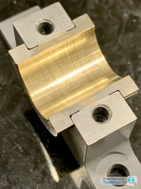
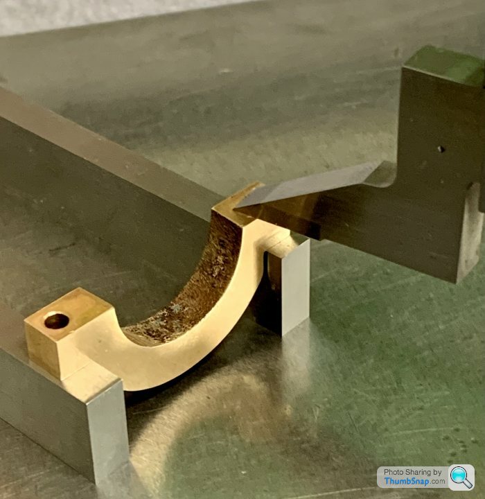
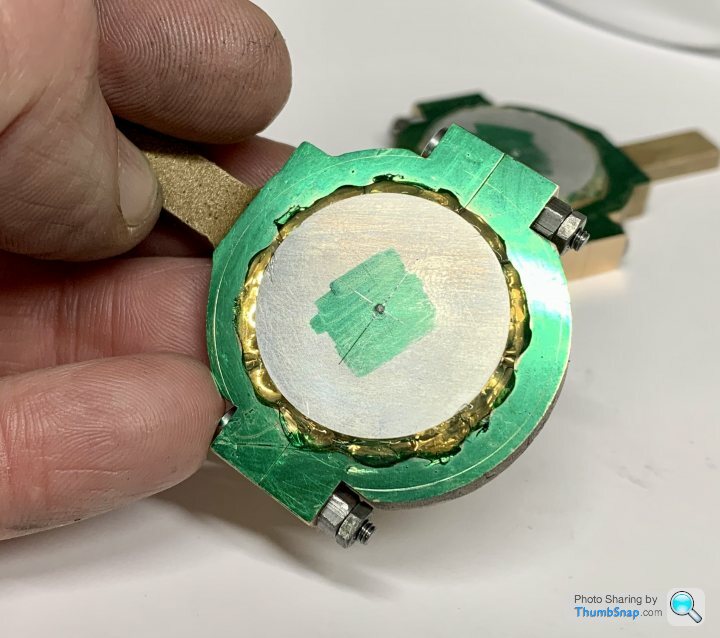
Then clamped in the spare housing:
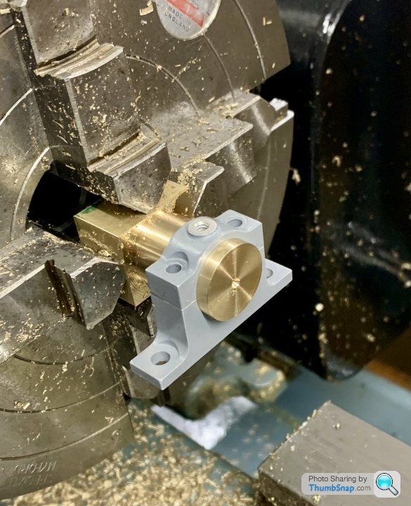
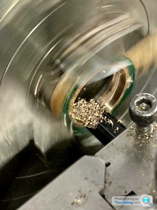
Drilled and bored to a good running fit on the shaft:
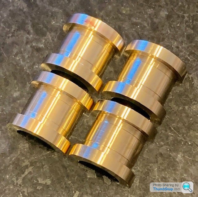
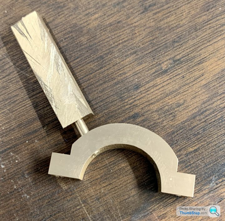
Then parted-off without issue. Again, judging and adjusting the cut to give the right flange dimension was very difficult:
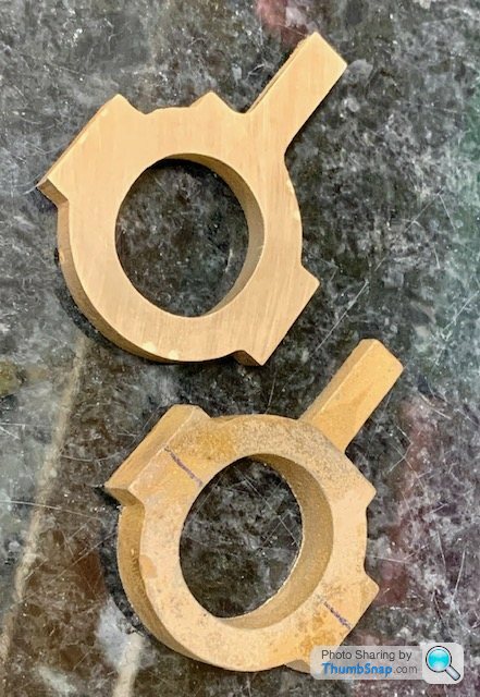
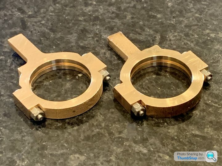
Here’s the result:

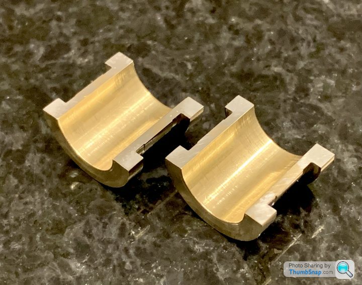
Fit seems fine, runs smoothly enough with the cap screws loosely tightened, but binds slightly when fully tightened.
So I’m calling that one OK. Now for the other side.
I cut the block in half to stiffen everything up:
Faced:
Flange O/D turned from square:
Set the grooving tool normal:
I had to use back-gear to avoid chatter, but all ok. The recess was by far the hardest part. Once again I found it difficult to judge dimensions and simultaneously machine a width and diameter without going over or undersize on one or the other. Having the saddle stop at one end was fine, but it’s fresh air at the other end, and very easy to go too far in the width while getting the diameter. What I did was get the width right, then when the diameter was almost there, undersize each end to avoid the pedestal radii. This left a raised block in the middle, and I changed tools to a normal turning tool to reduce that until it was the perfect diameter to match the housing. All a bit sketchy I think, but it worked.
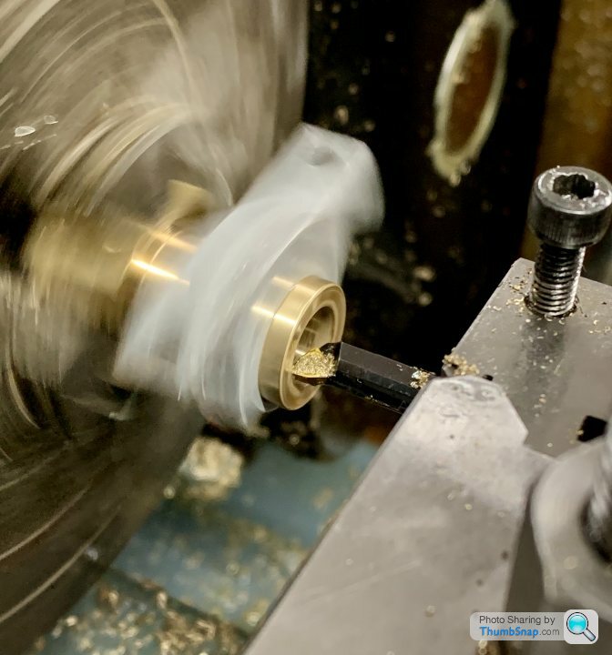
Then clamped in the spare housing:
Drilled and bored to a good running fit on the shaft:
Then parted-off without issue. Again, judging and adjusting the cut to give the right flange dimension was very difficult:
Here’s the result:
Fit seems fine, runs smoothly enough with the cap screws loosely tightened, but binds slightly when fully tightened.
So I’m calling that one OK. Now for the other side.

dudleybloke said:
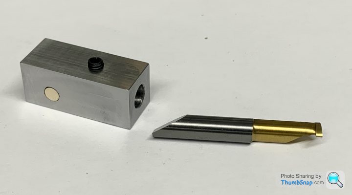
Do you have any negative rake cutters for doing the brass?
Nope. I think it should be zero rake for brass, but I've not had much problem with standard non-ferrous cutter inserts. Drilling is a different matter, and sometimes the drill will grab. I think you're supposed to knock the cutting edge off slightly, but since I don't really know how, and to what extent, I'll just go carefully rather than ruin a drill.Still struggling a bit with the straps - a bit of fettling needed, but I think I’m getting there.
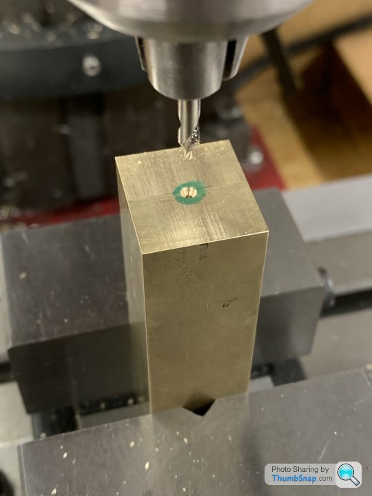
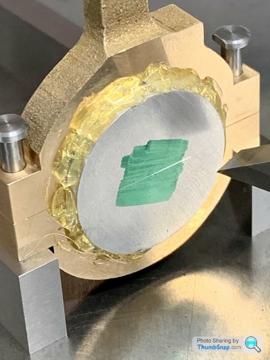
There was a casting flaw I didn’t pay much attention to, but since it turns out only about 0.3mm needs machining from the o/d, even roughly measuring a Blue-Tack positive impression showed it would definitely still leave a hole:
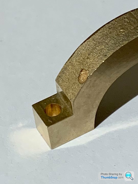
I milled a 3mm hole straight through the flaw, and turned some similar material (from the spare bearing blocks) to be a tight fit, then tinned with solder and sweated in place:
After filing back, I think it will be fine once finally machined:
There was a casting flaw I didn’t pay much attention to, but since it turns out only about 0.3mm needs machining from the o/d, even roughly measuring a Blue-Tack positive impression showed it would definitely still leave a hole:
I milled a 3mm hole straight through the flaw, and turned some similar material (from the spare bearing blocks) to be a tight fit, then tinned with solder and sweated in place:
After filing back, I think it will be fine once finally machined:
Gassing Station | Scale Models | Top of Page | What's New | My Stuff