Stuart Twin Victoria (Princess Royal) Mill Engine
Discussion


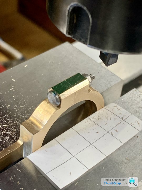
Set the fixture in the R/T:
And milled the outer profiles:
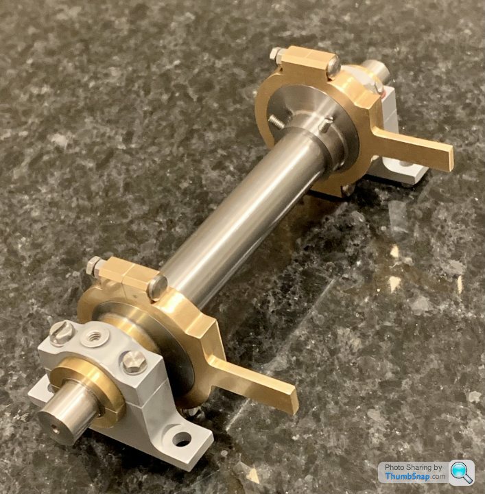
I used my EBay slip gauges, hot-glued together, to support the tail:
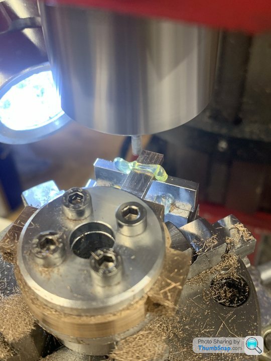
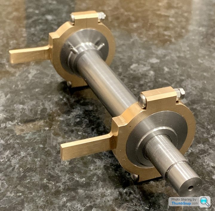
They seem ok - one is a bit off around the oiler pad for some reason. I think the pads are too small for an oil pot, so I guess I will need to spot-face them anyway:
I’ll also put chamfers along the square bolt boss edges.
These are a real pain. I’ve been playing catch-up and chasing my tail with various dimensions ever since the first hole went wrong.
And milled the outer profiles:
I used my EBay slip gauges, hot-glued together, to support the tail:
They seem ok - one is a bit off around the oiler pad for some reason. I think the pads are too small for an oil pot, so I guess I will need to spot-face them anyway:
I’ll also put chamfers along the square bolt boss edges.
These are a real pain. I’ve been playing catch-up and chasing my tail with various dimensions ever since the first hole went wrong.
Its finished!
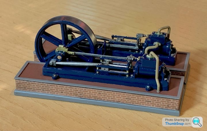
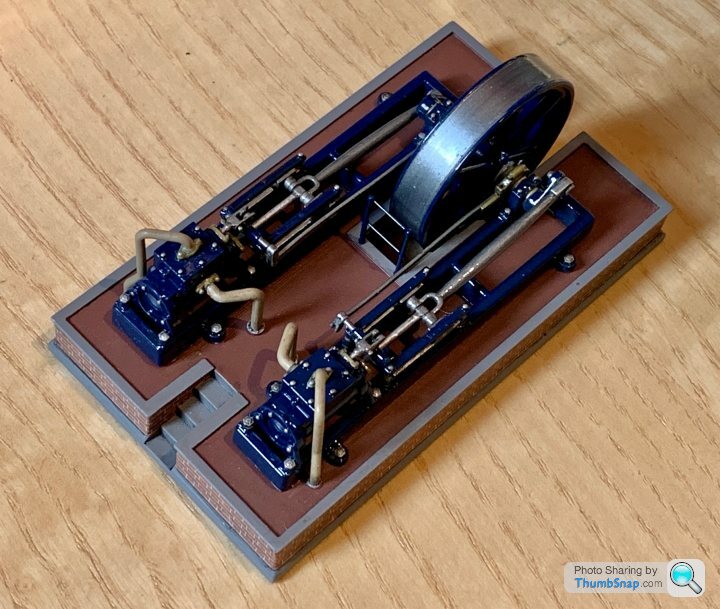
Well, this 3D printed version is - it's approximately OO scale:
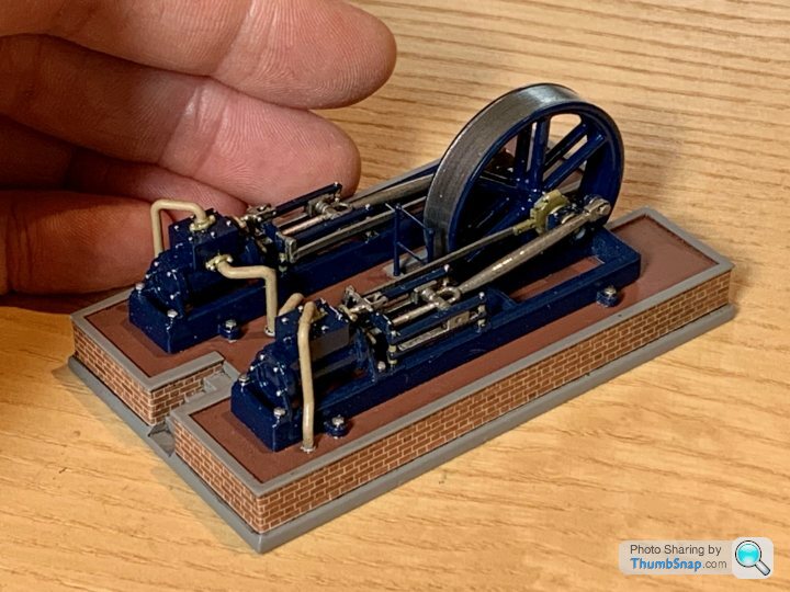
Jason Ballamy from the Model Engineer forum kindly gave me the CAD model he'd done for his single-cylinder version, and I mirrored it and moved the crankshaft and linkages slightly to form a twin. Then printed a base and wrapped some brick paper around it for a bit of scale.
It's now in place inside a mill building on a work colleague's OO railway (with the flywheel powered by a rubber belt).
Well, this 3D printed version is - it's approximately OO scale:
Jason Ballamy from the Model Engineer forum kindly gave me the CAD model he'd done for his single-cylinder version, and I mirrored it and moved the crankshaft and linkages slightly to form a twin. Then printed a base and wrapped some brick paper around it for a bit of scale.
It's now in place inside a mill building on a work colleague's OO railway (with the flywheel powered by a rubber belt).
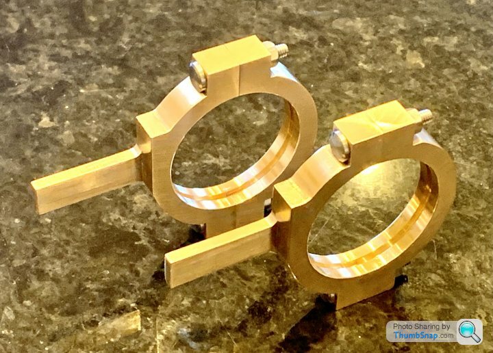
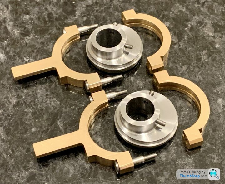
I wasn’t 100% happy with one of the eccentric strap profiles back in March, and I lost a bit of motivation to make another - they had taken a great deal of time and effort (even to get one slightly wrong 😂). Anyway, three months later I’ve finally made another, which is spot-on. Also added chamfers to the edges to neaten the bosses up. Just need spot-facing for the oilers, and they will both be done.
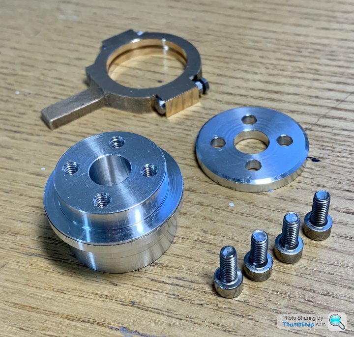
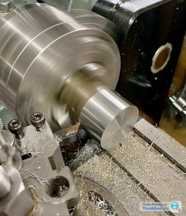
Started on the eccentric sheaves. Turned down some mild steel to the locating ring diameter:
Marked out:
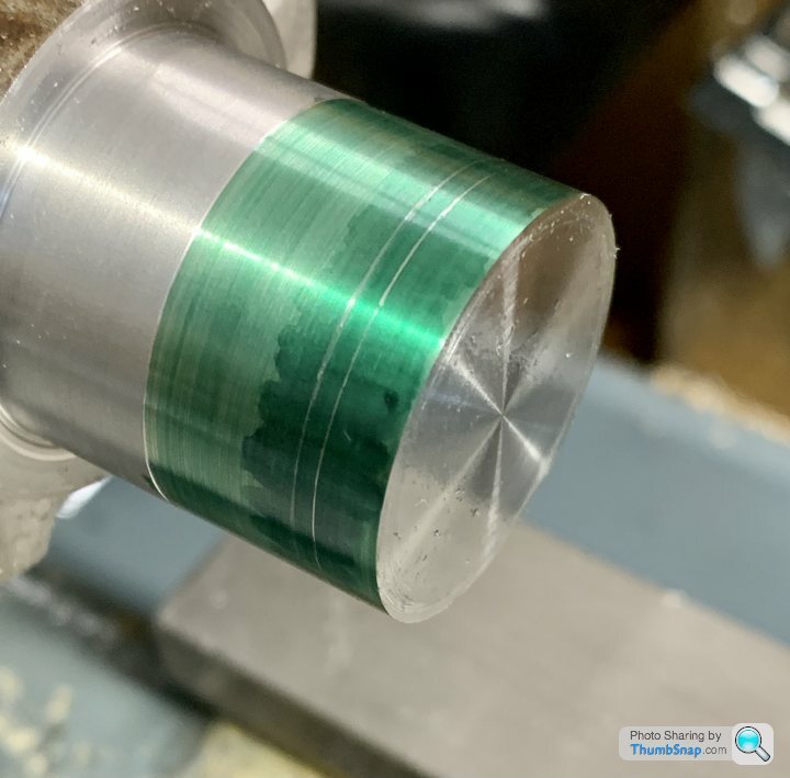
Then once machined to a perfect fit on the straps, cut it off and put in the chuck for facing and marking out for the eccentric offset. Padded the chuck jaws with paper to protect the bearing surfaces, and it immediately moved in the chuck, snapping the tool and trashing the part. Strange thing is I almost knew it was going to do that, but did it anyway. Very odd:
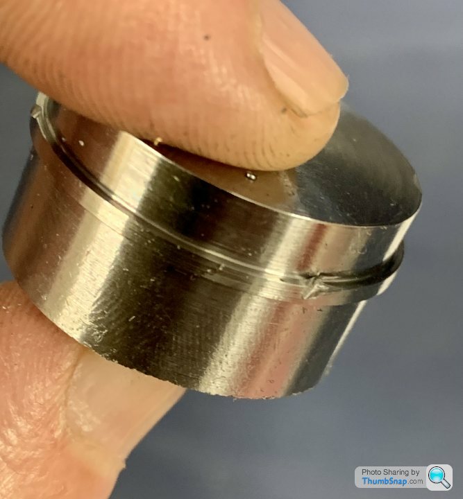
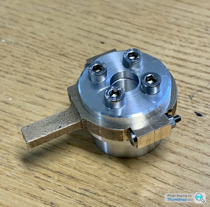
Second attempt:
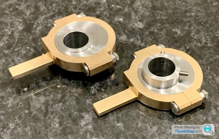
Test fit:
The strap halves just lock onto the eccentric when tight, they need a slight gap between the joint faces:
I think this is right, so they can be adjusted for wear, and that’s why the strap caps have lock-nuts.
I’ll leave the sawing and chucking until tomorrow I think. I need to figure out a method of securely holding in the chuck without damaging them. Maybe an aluminium ring.
Marked out:
Then once machined to a perfect fit on the straps, cut it off and put in the chuck for facing and marking out for the eccentric offset. Padded the chuck jaws with paper to protect the bearing surfaces, and it immediately moved in the chuck, snapping the tool and trashing the part. Strange thing is I almost knew it was going to do that, but did it anyway. Very odd:
Second attempt:
Test fit:
The strap halves just lock onto the eccentric when tight, they need a slight gap between the joint faces:
I think this is right, so they can be adjusted for wear, and that’s why the strap caps have lock-nuts.
I’ll leave the sawing and chucking until tomorrow I think. I need to figure out a method of securely holding in the chuck without damaging them. Maybe an aluminium ring.
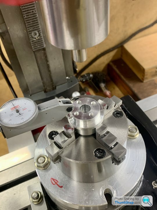
So tonight I spent 6 hours on the new eccentric, only to realise that I’ve made another mistake. I left some excess on the smaller raised eccentric boss length, but then sawed it off and faced it without adding the excess. So I’ve ended up with the right overall width, but the eccentric ring is too far over.
I only realised after setting it up in the R/T to drill the 90 degree grub screw holes:
It was turned, drilled and bored, and was pretty much spot-on. I’ve now used all my mild steel stock, so will have to get some more.
I don’t know whether my concentration is going, or whether there’s something up with me, but I can’t seem to make any progress with anything these days. I seem to be making mistakes at every stage. If I’m honest I’m quite demoralised.
Do something completely different; the trigger valve on the pressure washer has a nylon cup washer which had fallen to bits, having not used the lathe in a long time(and finding it had been used as a shelf by miscreants!) it was a nice easy job and has started me thinking about things to turn up.
hidetheelephants said:
Do something completely different; the trigger valve on the pressure washer has a nylon cup washer which had fallen to bits, having not used the lathe in a long time(and finding it had been used as a shelf by miscreants!) it was a nice easy job and has started me thinking about things to turn up.
Thing is I've not worked on this since March. At this rate of work it'll be in the same place as the Airfix Vulcan - it'll never get done. I didn't re-draw the eccentrics and convert them to metric. I might do that so I get used to how to dimension them properly rather than trying to interprest two sets of drawings plus what I've already made that they have to fit to...
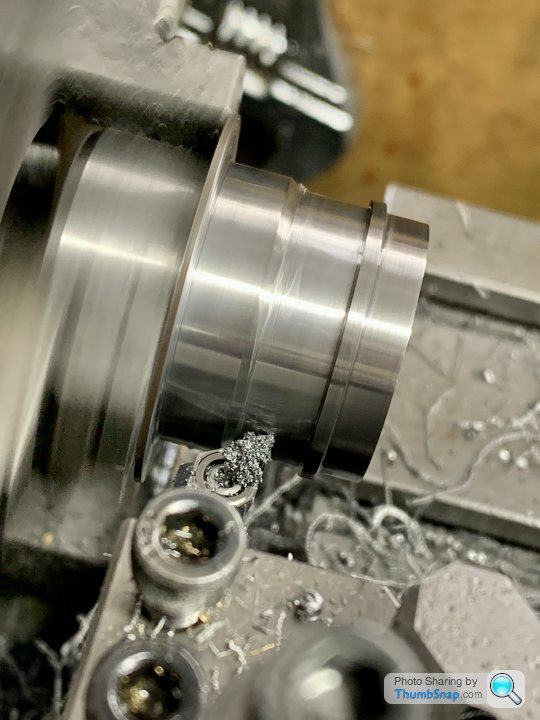
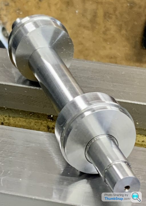
So we go again. I bought some new steel bar (£3.50!)
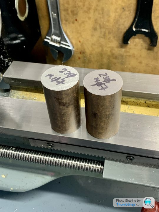
And turned the O/Ds to profile, and this time with the correct offsets:
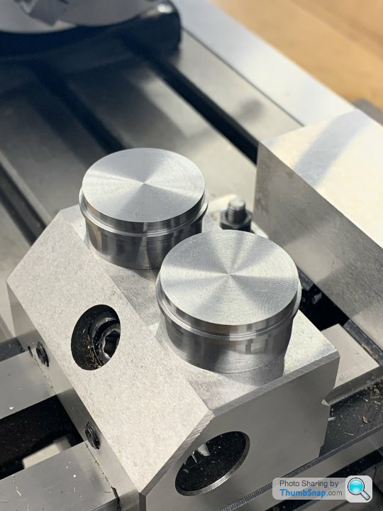
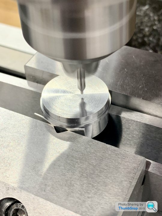
Centered them in the mill:
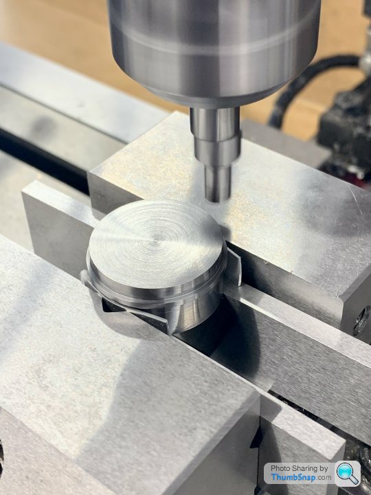
And centre drilled them offset by 1/8”
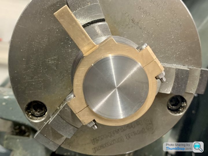
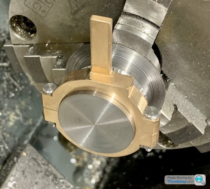
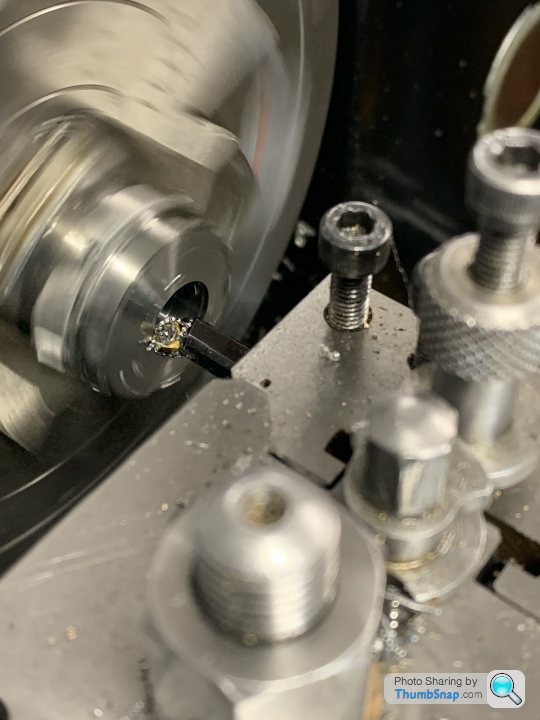
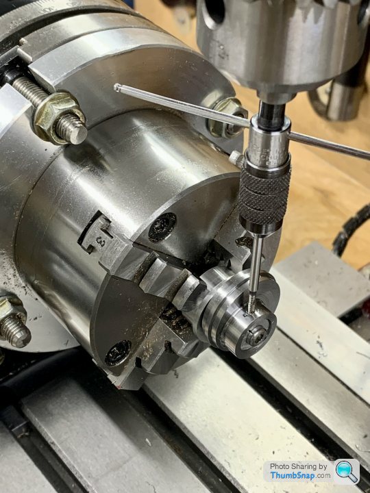
Set up in the 4-jaw chuck:
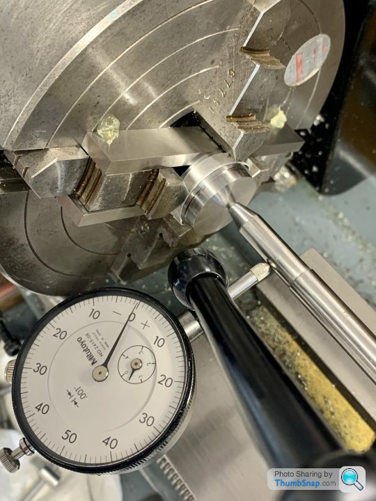
Drilled:
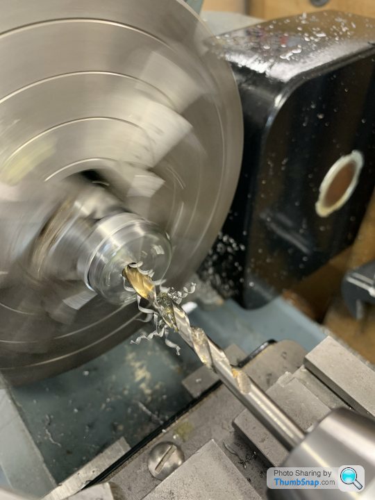
Then bored to a location fit on the crankshaft:
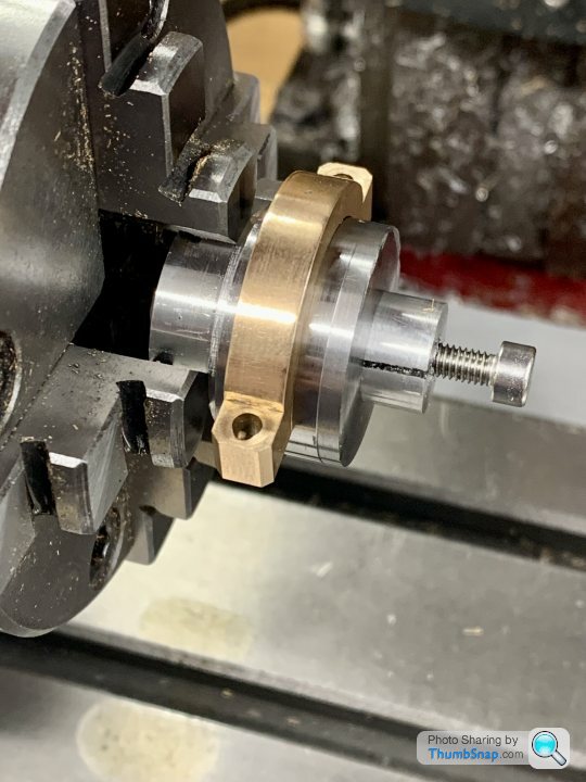
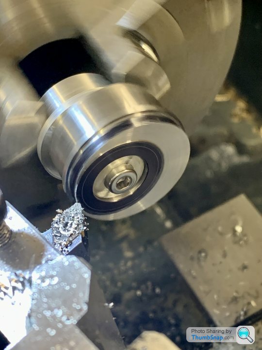
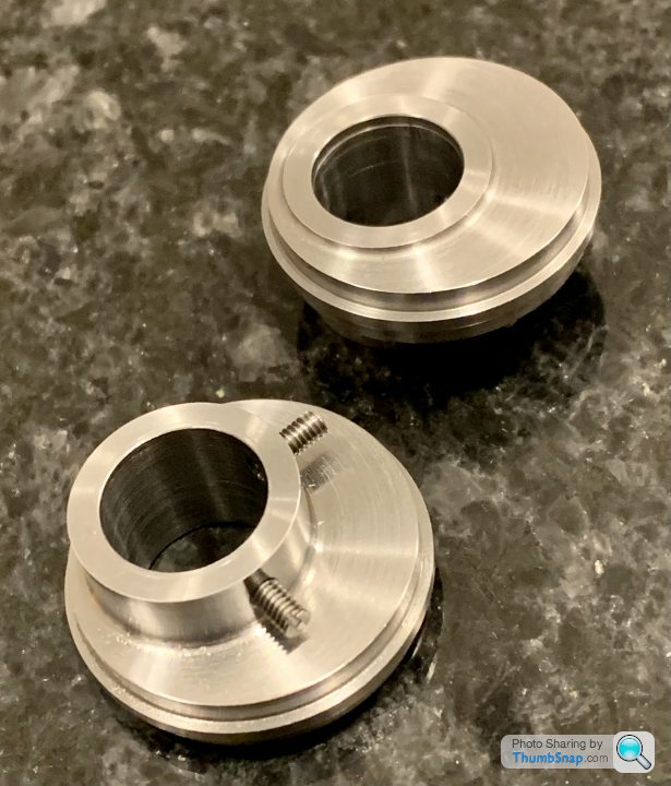
Then fitted into the expanding mandrel and machined the bosses:
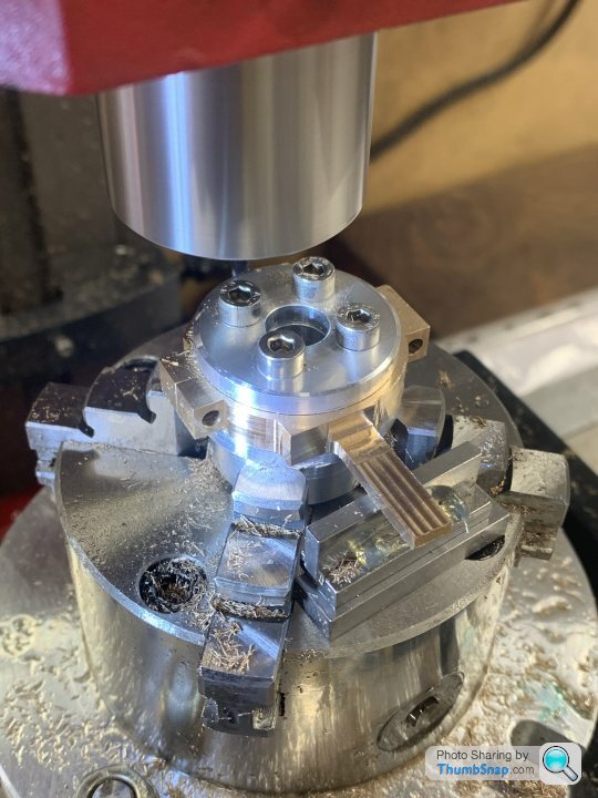
Then over to the mill and setup in the R/T for drilling the 90 degree spaced 7BA grub screw holes:
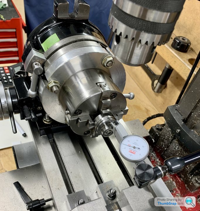
So that’s the eccentric sheaves done apart from trimming the grub screws:
Crankshaft test fitted with the parts I’ve made so far. Still got to cut the grooves in the shaft under the grub screws as per Ramon’s suggestion IIRC:
And turned the O/Ds to profile, and this time with the correct offsets:
Centered them in the mill:
And centre drilled them offset by 1/8”
Set up in the 4-jaw chuck:
Drilled:
Then bored to a location fit on the crankshaft:
Then fitted into the expanding mandrel and machined the bosses:
Then over to the mill and setup in the R/T for drilling the 90 degree spaced 7BA grub screw holes:
So that’s the eccentric sheaves done apart from trimming the grub screws:
Crankshaft test fitted with the parts I’ve made so far. Still got to cut the grooves in the shaft under the grub screws as per Ramon’s suggestion IIRC:
Well done all coming along nicely.
Tou will soon be catching up with your printed version.
My thoughts, for what its worth, would be when you shorten the grubscrews, to use the internal allen key type, as over the years i have lost count of the blade type grub screw sides that have sheared off when trying to get them out again.
Keep up the excellent work.
rolster said:
Well done all coming along nicely.
Tou will soon be catching up with your printed version.
My thoughts, for what its worth, would be when you shorten the grubscrews, to use the internal allen key type, as over the years i have lost count of the blade type grub screw sides that have sheared off when trying to get them out again.
Keep up the excellent work.
I'll add my congrats to dr_gn.Tou will soon be catching up with your printed version.
My thoughts, for what its worth, would be when you shorten the grubscrews, to use the internal allen key type, as over the years i have lost count of the blade type grub screw sides that have sheared off when trying to get them out again.
Keep up the excellent work.
And yes, I agree about the grubscrews. Internal hex are a lot less prone to damage.
Thanks guys.
I thought I do something a bit simpler, so I started on the crosshead slider blocks.
Started by cutting some sections of brass roughly to size:
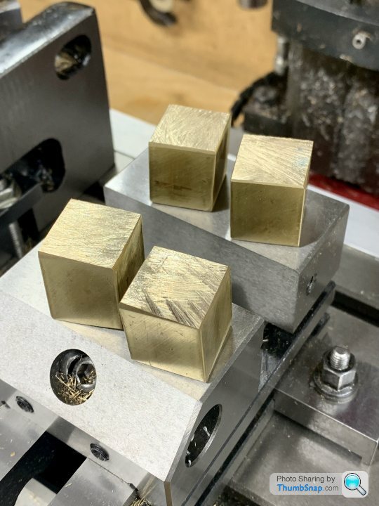
Then set them up in pairs in the vice and machined five faces in the same setup:
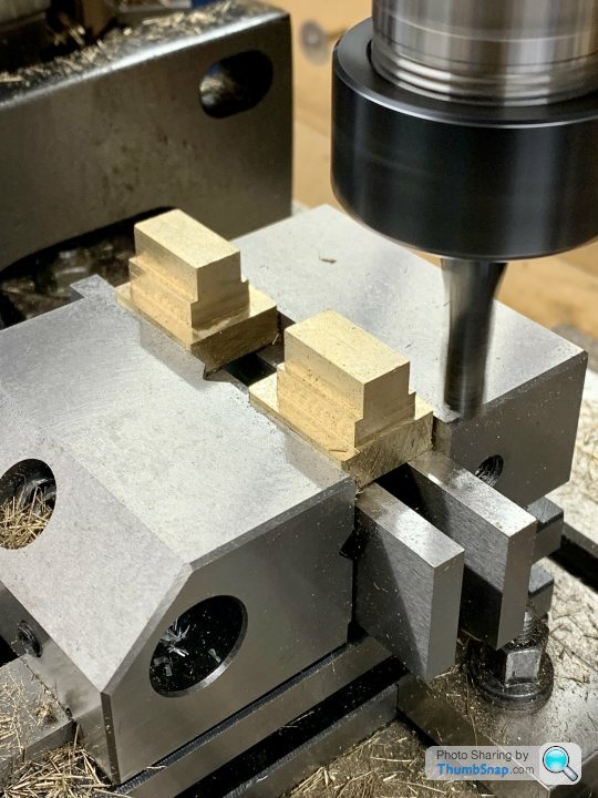
Then drilled and reamed the holes:
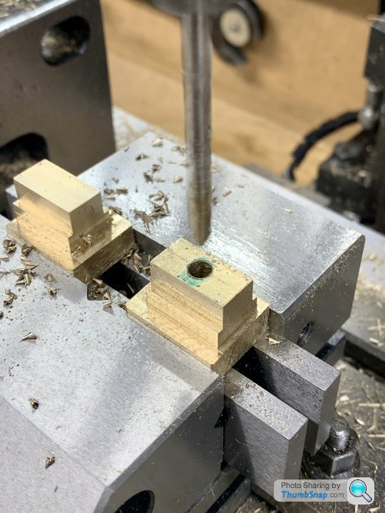
Then put in the 4-jaw chuck to turn the bosses:
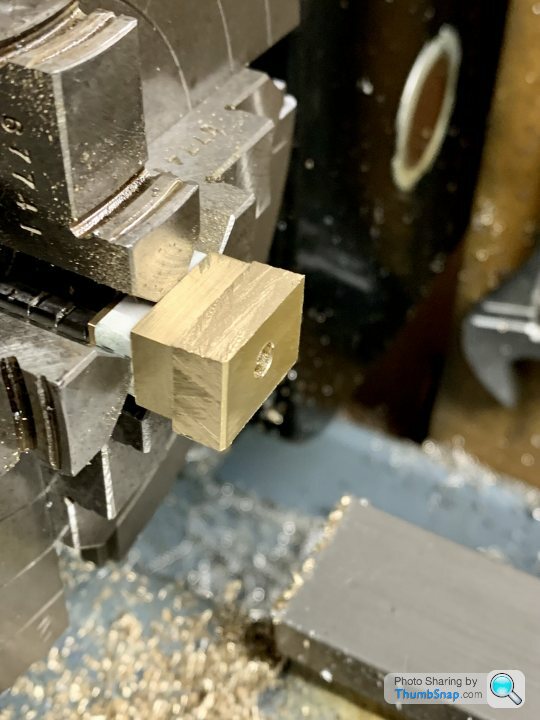
I left 0.010” on the boss lengths in case they need fettling to fit between the slides.
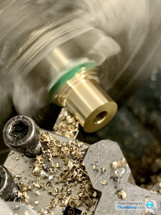
Done, apart from some minor surface finishing:
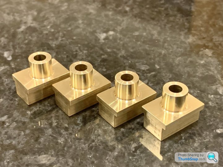
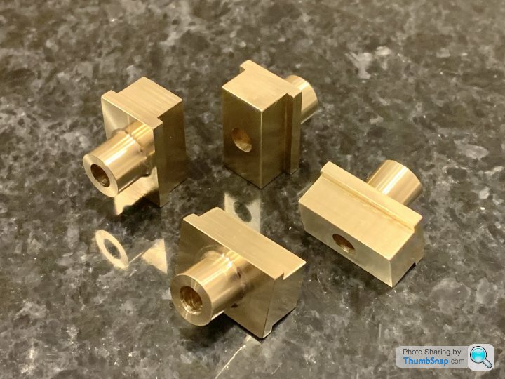
I used a 0.8mm radius turning insert to get the fillet. Might be a bit small, but I’m still avoiding grinding tools unless there’s absolutely no other choice.
I thought I do something a bit simpler, so I started on the crosshead slider blocks.
Started by cutting some sections of brass roughly to size:
Then set them up in pairs in the vice and machined five faces in the same setup:
Then drilled and reamed the holes:
Then put in the 4-jaw chuck to turn the bosses:
I left 0.010” on the boss lengths in case they need fettling to fit between the slides.
Done, apart from some minor surface finishing:
I used a 0.8mm radius turning insert to get the fillet. Might be a bit small, but I’m still avoiding grinding tools unless there’s absolutely no other choice.
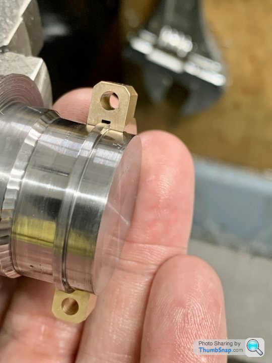
Started on the forked ends for the piston rods. These are made from Mild Steel:
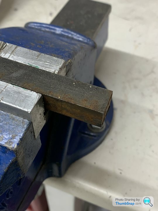
Set them in the mill vice and machined 5 faces to size:
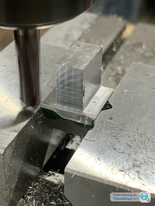
Side milling has always been problematic on my mill. I think it’s a stiffness issue with one or more axis. At one point it dragged the cutter into the vice and took a chunk out of the jaw. Not happy. Strangely, no problem at all with the long faces - quite happily took shallow full depth cuts, but the short ones were hopeless even with incrementing the depth. You can probably see the difference in surface finish.
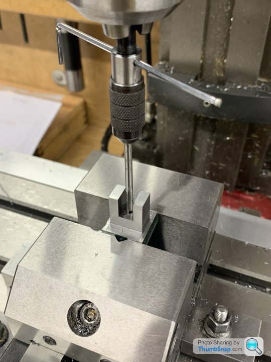
Then milled the central slot:
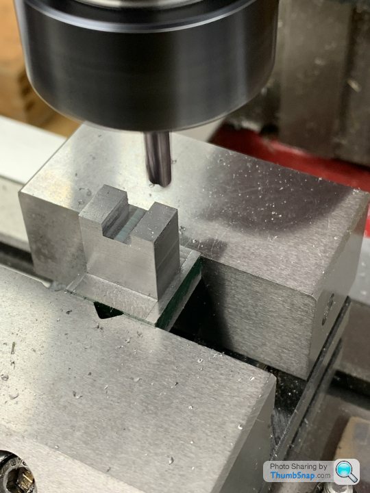
Drilled and tapped the 5BA thread:
Then set in the 4-jaw and turned the bosses:
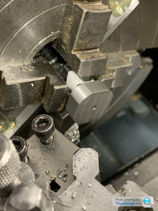
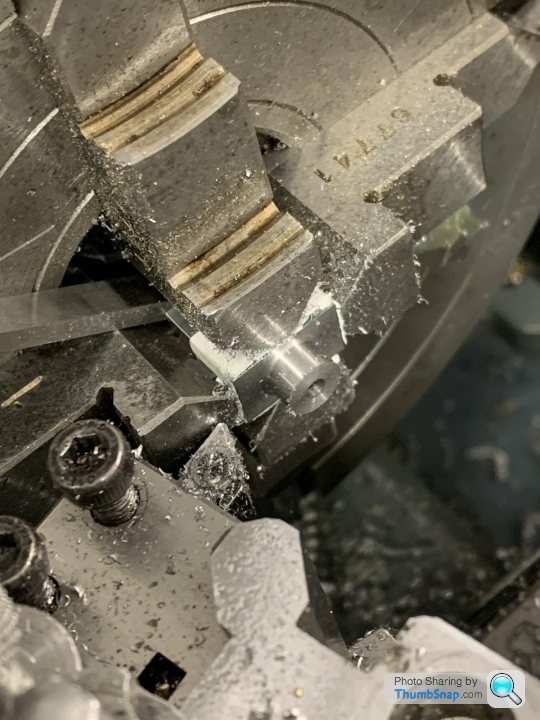
Apart from the shaft holes and locking screw holes, they are done:
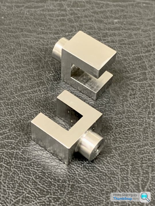
They look pretty crude compared with other parts, I’m wondering whether to add some chamfers on the boss annd shoulders, and round off the forked ends.
Set them in the mill vice and machined 5 faces to size:
Side milling has always been problematic on my mill. I think it’s a stiffness issue with one or more axis. At one point it dragged the cutter into the vice and took a chunk out of the jaw. Not happy. Strangely, no problem at all with the long faces - quite happily took shallow full depth cuts, but the short ones were hopeless even with incrementing the depth. You can probably see the difference in surface finish.
Then milled the central slot:
Drilled and tapped the 5BA thread:
Then set in the 4-jaw and turned the bosses:
Apart from the shaft holes and locking screw holes, they are done:
They look pretty crude compared with other parts, I’m wondering whether to add some chamfers on the boss annd shoulders, and round off the forked ends.
Gassing Station | Scale Models | Top of Page | What's New | My Stuff