Stuart Twin Victoria (Princess Royal) Mill Engine
Discussion


So it’s the one year anniversary of starting the 10V, so I made a start on this one. This time with some help:
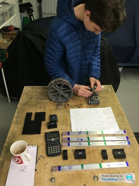
We got the castings and bed material out - shows how much work this is going to be:

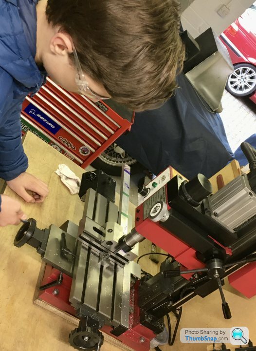
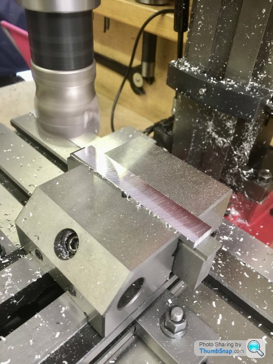
After re-figuring out how all the 3D printed jigs were supposed to work, fist job was to trim the bed plate sides to length on the mill:
Small start, but it’s a start.
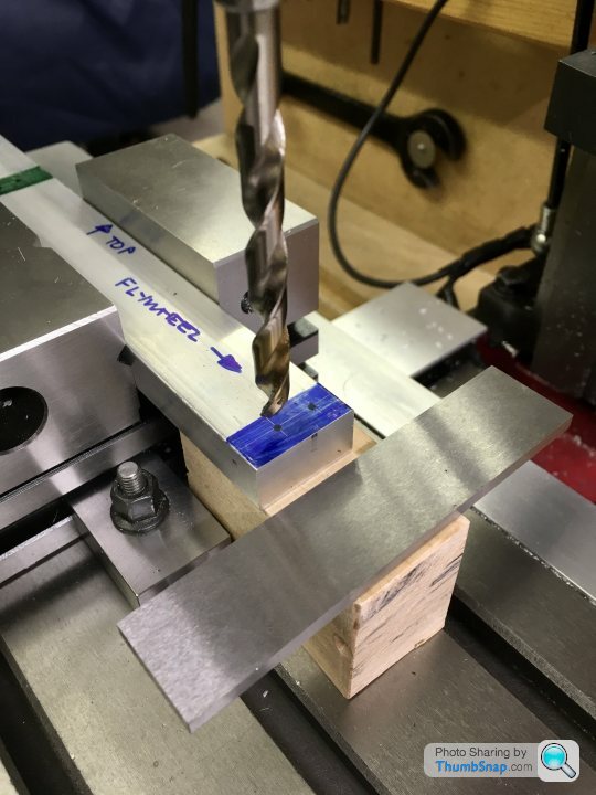
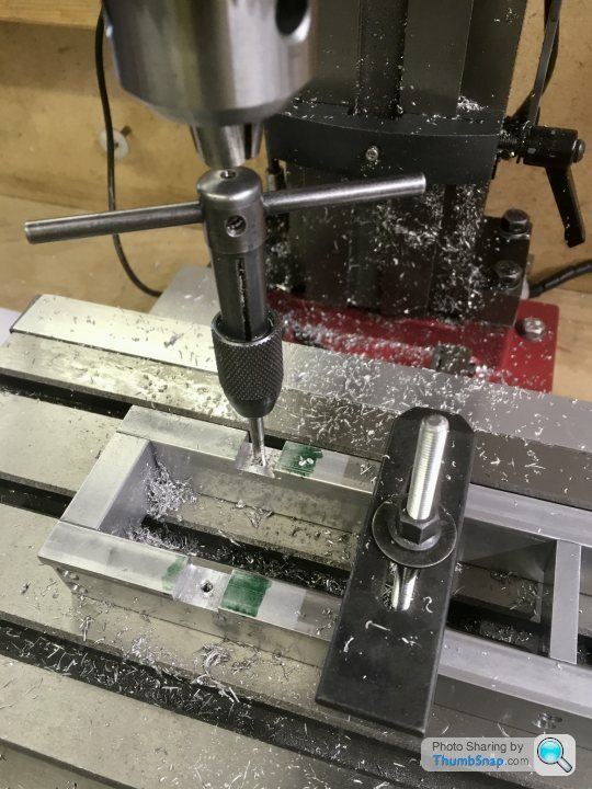
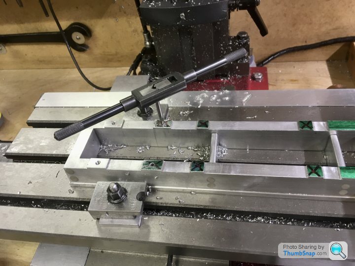
Next job is to co-ordinate drill the counterbored holes.
We got the castings and bed material out - shows how much work this is going to be:
After re-figuring out how all the 3D printed jigs were supposed to work, fist job was to trim the bed plate sides to length on the mill:
Small start, but it’s a start.
Next job is to co-ordinate drill the counterbored holes.
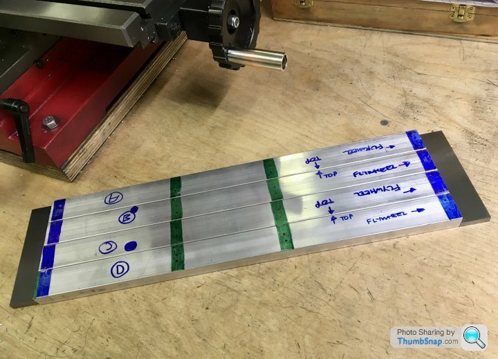
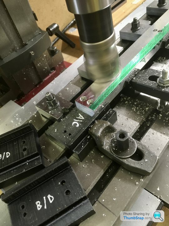
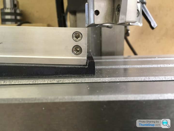
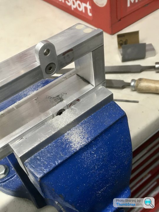
Got the holes drilled and counterbored, they all match - so far.
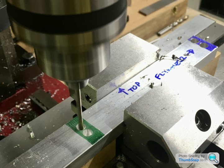
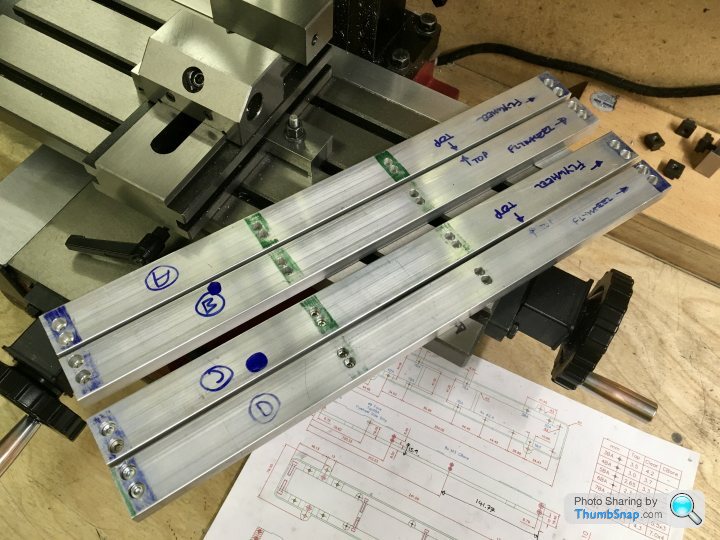
Very easy to get them mixed up, I’ll have to keep the markings clear to prevent a time consuming mistake.
Still have to drill sockets for the linkage bosses in the inner walls (B & C), then we will see if the 3D printed casting draft jigs work...
Very easy to get them mixed up, I’ll have to keep the markings clear to prevent a time consuming mistake.
Still have to drill sockets for the linkage bosses in the inner walls (B & C), then we will see if the 3D printed casting draft jigs work...
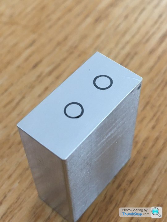
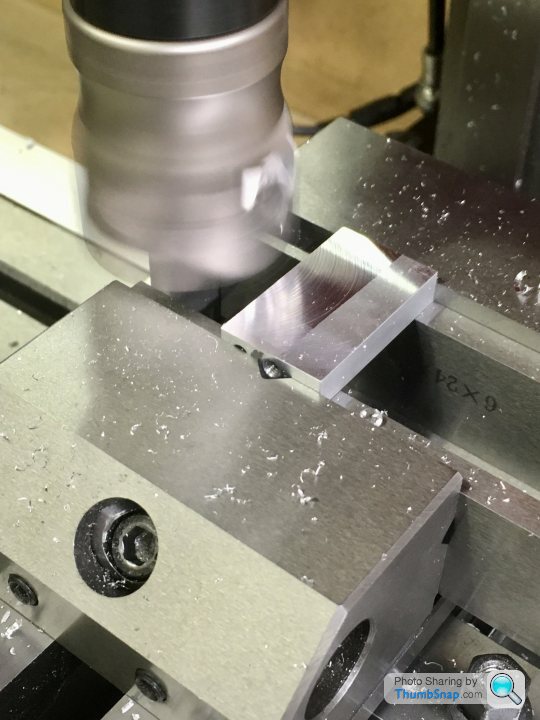
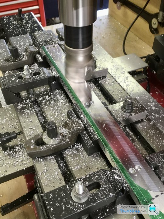
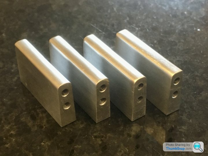
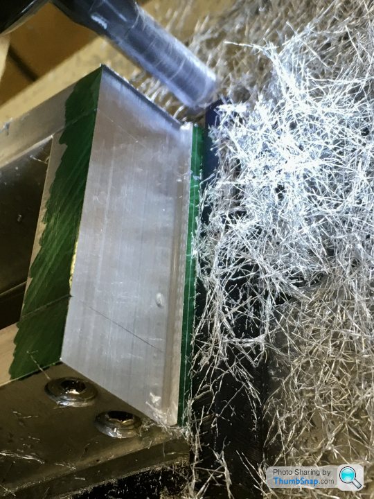
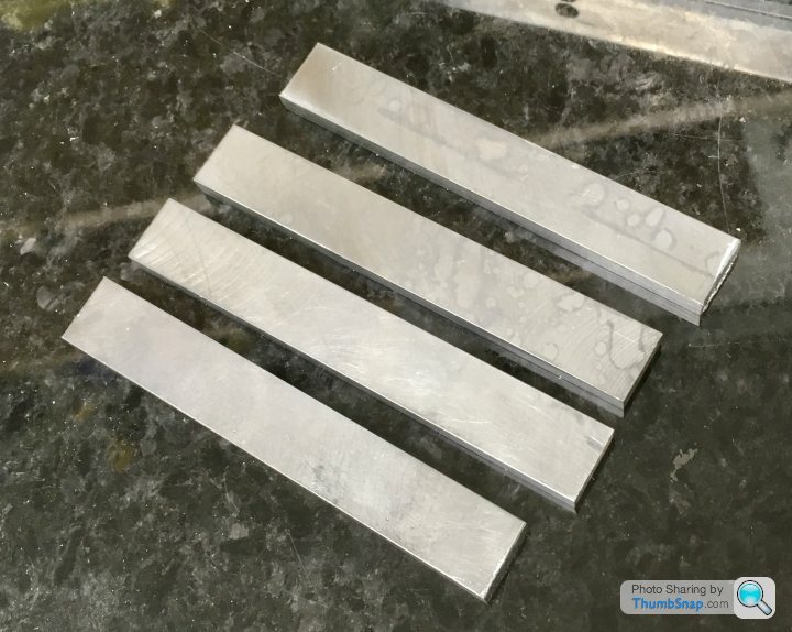
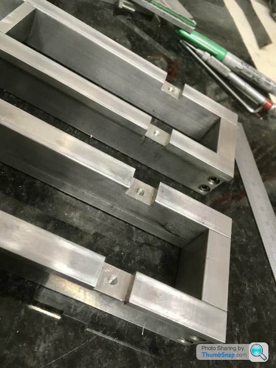
Decided to get on with the bed cross-pieces and ends. First job: saw 8x blocks a bit oversized, and de-burr:
Then machine to the right width with the shell mill. This wasn’t as easy as it seemed for some reason, and took several goes to get the corners 90 degrees according to the engineer’s square:
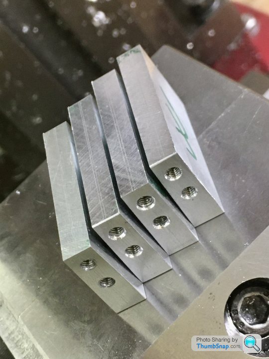
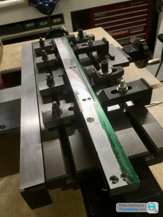
I’d machined an end stop for the vice during my dormant modelling phase, and this came in handy as a fixture for the 32 drilled and tapped holes:
Because of the way I’d designed the ends to allow for tapered outer faces, the holes aren’t on the central axis of the end pieces, they are offset inwards slightly. This tripped me up on the first piece, which gave a staggered end:
another lesson learned. I JB Welded some aluminium rod into the holes, faced off and re-drilled. It’s spot-on now.
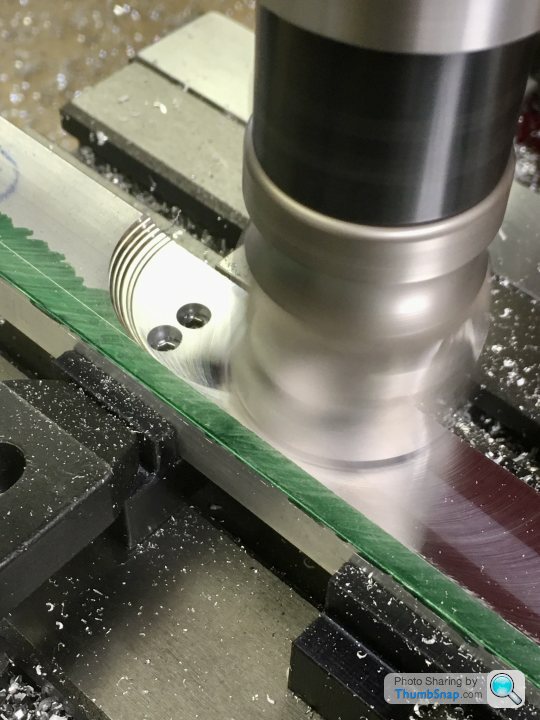
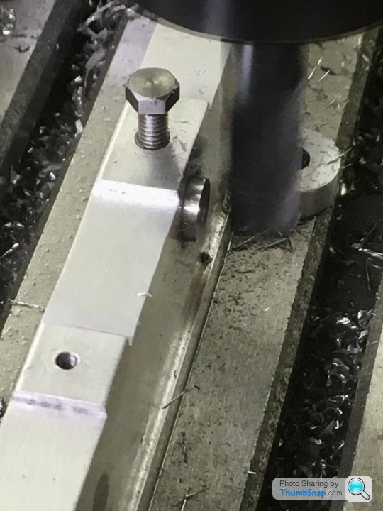
Then the middle spacers were drilled and tapped, and reduced in height by 5.4mm:
Made another error by drilling the first hole M4 as per the ends, should be M3 to accommodate the taper. Silly error, especially when using my own design/drawings. Anyway, as with the ends, I realised after the first one, and that’ll be corrected by tomorrow. So here we are now:
Next job is to disassemble again, and drill a couple of blind holes in the inner sides for the bosses for the throttle bell cranks, then it’ll be machining the tapers on all the components.
Then machine to the right width with the shell mill. This wasn’t as easy as it seemed for some reason, and took several goes to get the corners 90 degrees according to the engineer’s square:
I’d machined an end stop for the vice during my dormant modelling phase, and this came in handy as a fixture for the 32 drilled and tapped holes:
Because of the way I’d designed the ends to allow for tapered outer faces, the holes aren’t on the central axis of the end pieces, they are offset inwards slightly. This tripped me up on the first piece, which gave a staggered end:
another lesson learned. I JB Welded some aluminium rod into the holes, faced off and re-drilled. It’s spot-on now.
Then the middle spacers were drilled and tapped, and reduced in height by 5.4mm:
Made another error by drilling the first hole M4 as per the ends, should be M3 to accommodate the taper. Silly error, especially when using my own design/drawings. Anyway, as with the ends, I realised after the first one, and that’ll be corrected by tomorrow. So here we are now:
Next job is to disassemble again, and drill a couple of blind holes in the inner sides for the bosses for the throttle bell cranks, then it’ll be machining the tapers on all the components.
dudleybloke said:
A good start but you won't be getting your peicework bonus this month!
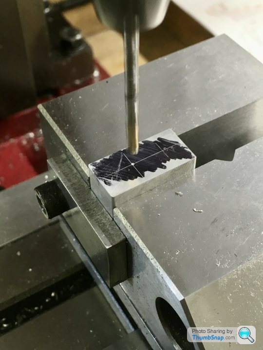
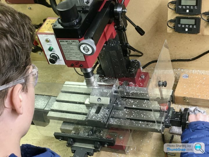
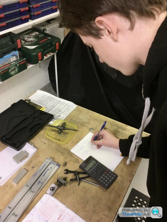
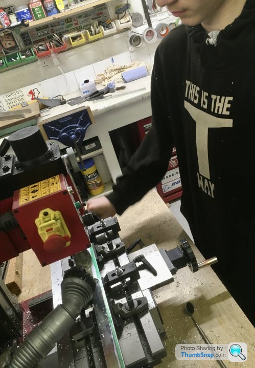
My excuse is that as well as figuring out how to do things myself, I’m then explaining what I’m thinking to my 13 y/o son, then showing him how to use measuring equipment and operate machine tools from pretty much scratch. He’s keen to try to do everything himself (for now!), and it’s nice to work together on something, but it’s inevitably a much slower process. I’m also wary of contradicting what he’s being taught in GCSE engineering...anyway, it is what it is.So this evening’s job was machining the middle bed spacers to thickness:

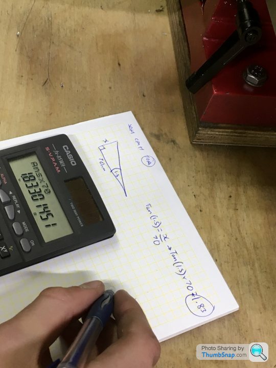
Then machining on the simulated casting draw taper. This was a good opportunity for the boy to apply the trigonometry He’s only just done in maths at school. No problem at all - measured the hypotenuse:
And worked out the depth of spacer needed to tilt the vice at 1.5 degrees. Good example of using trig, good timing too.
So we found some scrap, raised the vice and cut the first sides:
Then came the confusion. My assumption was that to get a symmetrical 3 degree taper on the blocks, all we had to do was machine 1.5 degrees on one face, flip it in the vice and machine the other face. I’d assumed that the 1.5 degree face would add to the 1.5 degree vice tilt, giving an overall 3 degrees. When I told him to do this he was having none of it; said it would either give zero degrees, or an asymmetric taper, and that we needed a 3 degree tilt for the second cut. Somewhat taken aback, I decided to prove my point with 2D CAD. Turns out he was right I think.
So we put one of the 3D printed 3 degree wedges I’d made for the long sides under the vice:
And cut the faces:
And they turned out spot-on:
They just need rounds filing on the top edges.
So I suppose the moral is, don’t assume your student necessarily knows less than you.
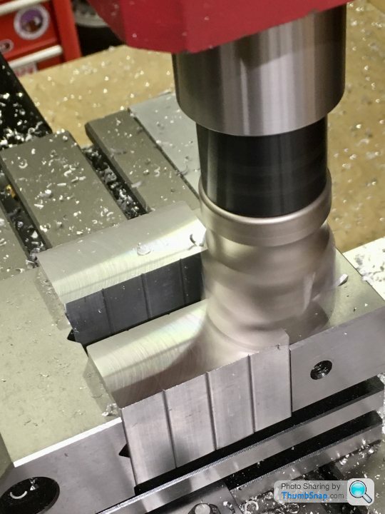
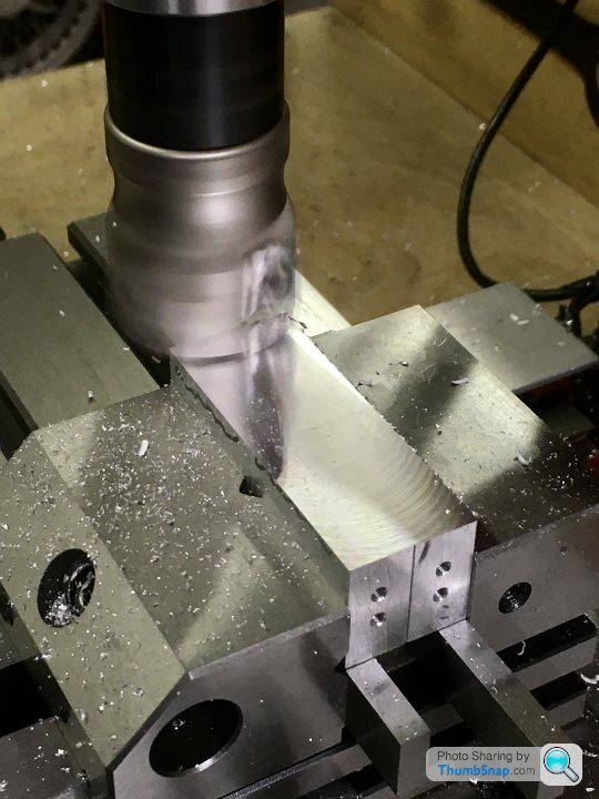
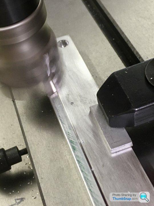
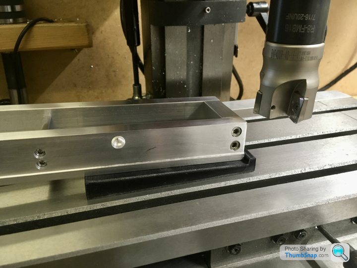
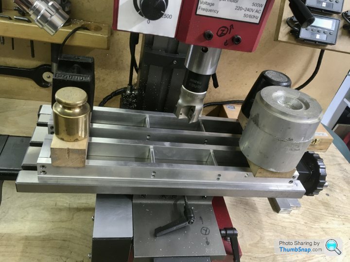
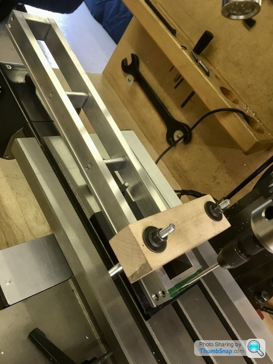
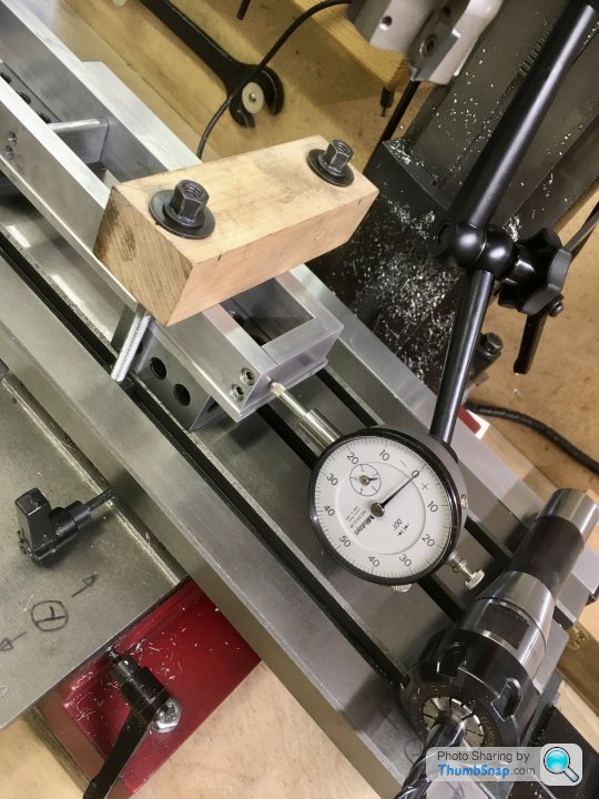
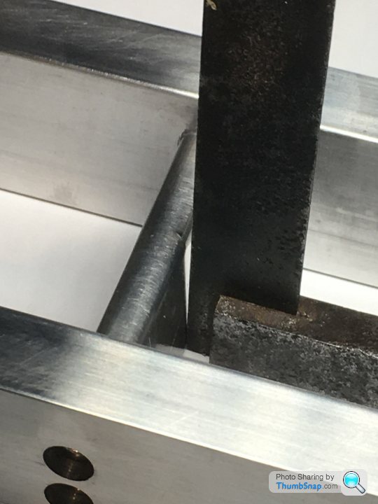
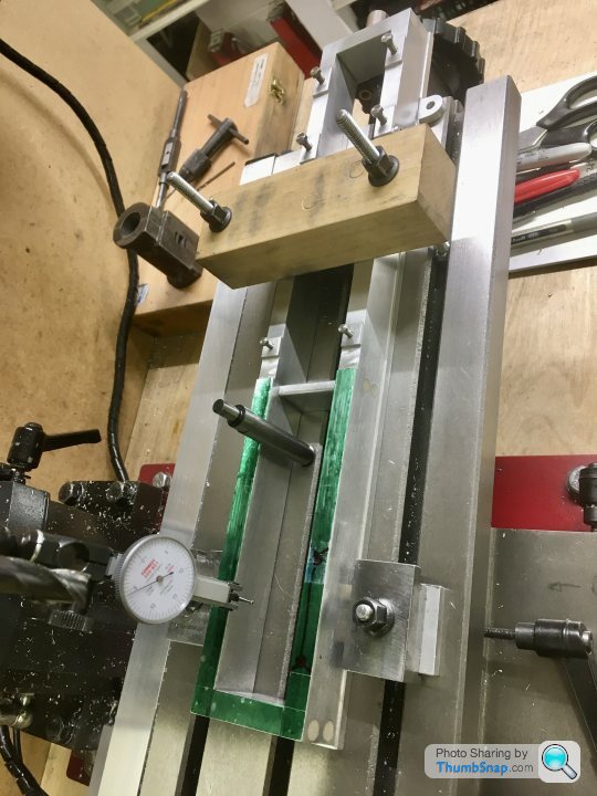
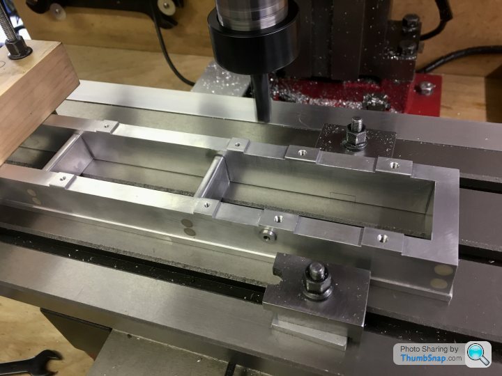
Finally got around to using the 3D printed taper jigs today. Set up parallel with the bed, and checked both workpiece positions (they are too long to do in one pass):
Marked out the extents of the taper, and carefully made the first cuts:
un u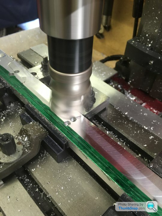
All seemed fine, so swapped positions and machines the other end to the same DRO z setting:
With the first pair complete, removed the jigs and replaced with those for the opposite hand, and repeated the process:
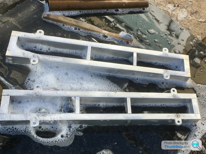
The time and effort in designing the jigs was worth it - in the end they worked perfectly and the whole process was fairly trivial. A few swirls to flat out, but nothing major.
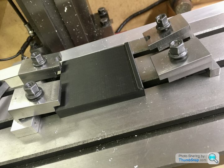
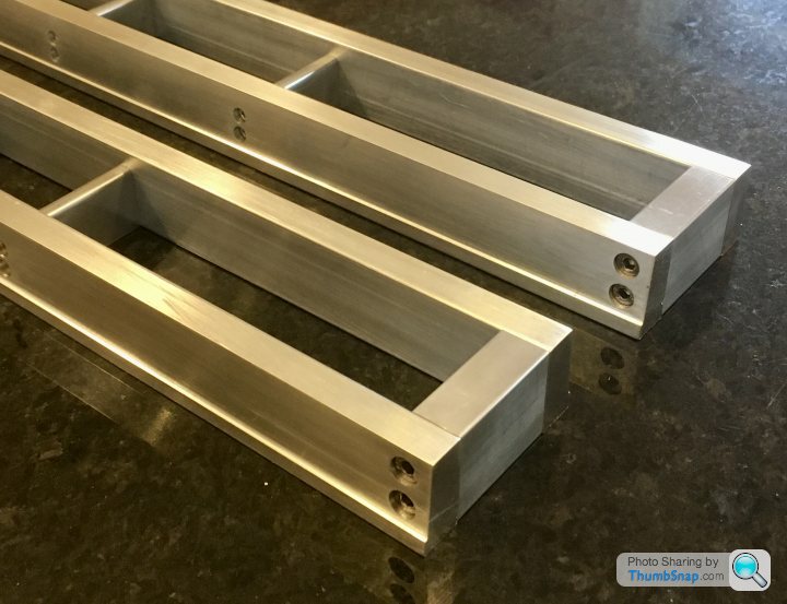
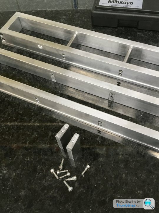
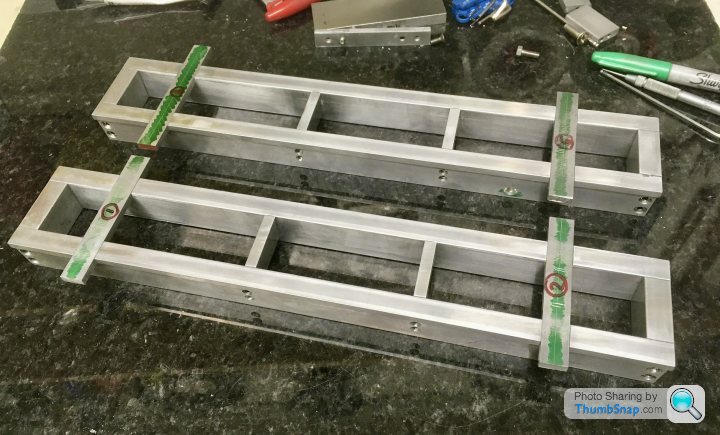
Final job on the sides was to reduce the plinth widths by 0.65mm:
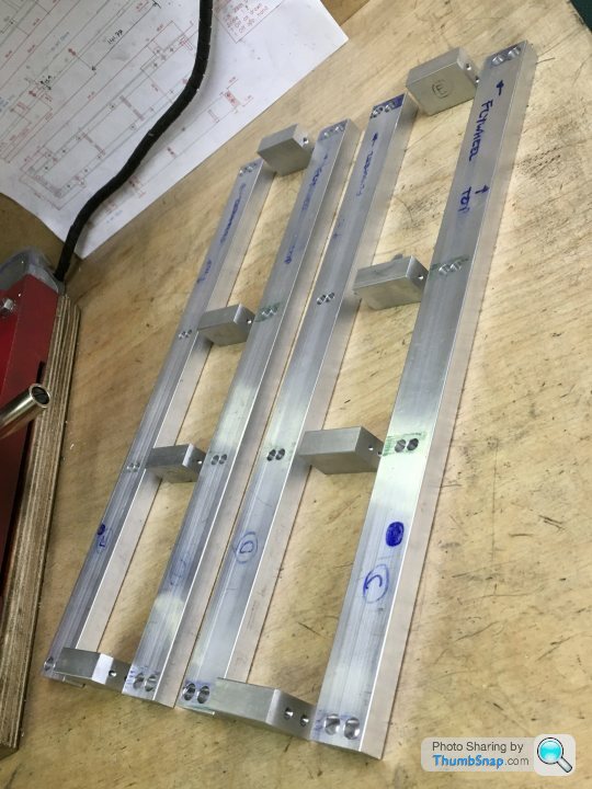
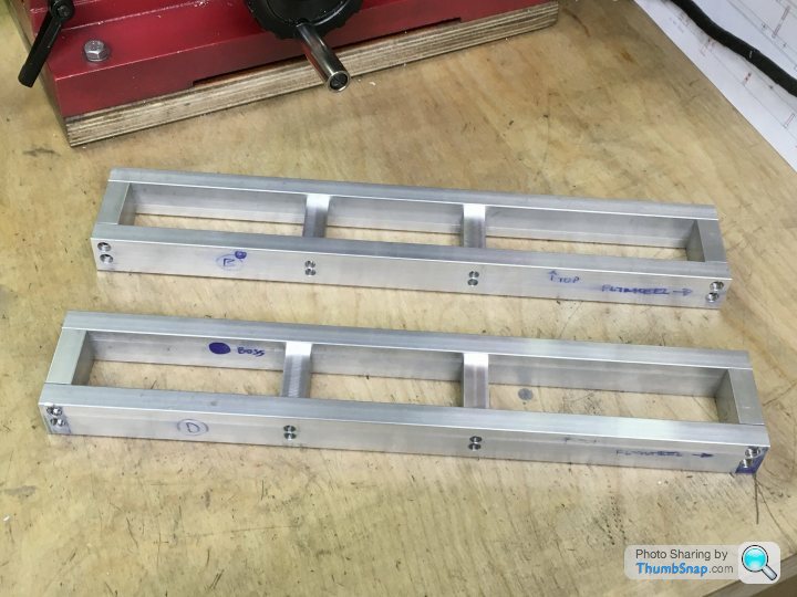
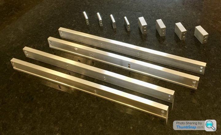
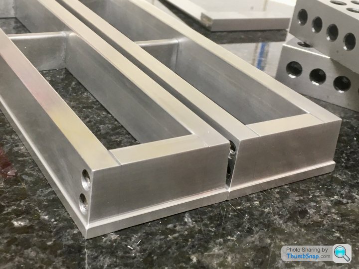
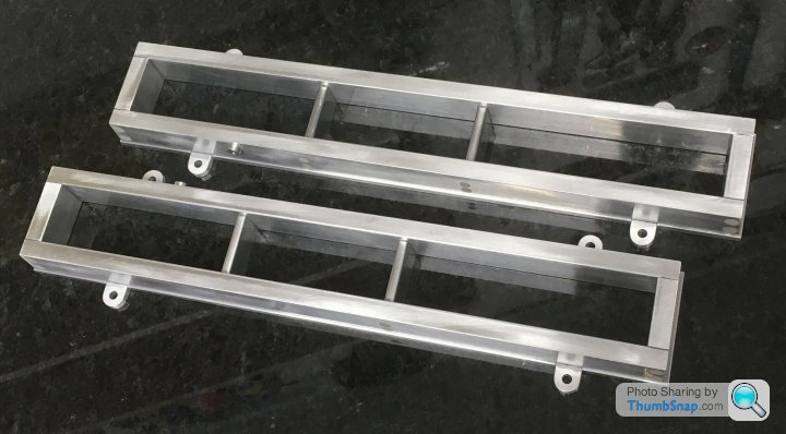
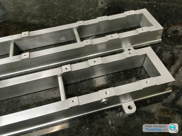
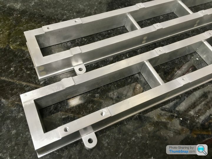
Finished parts:


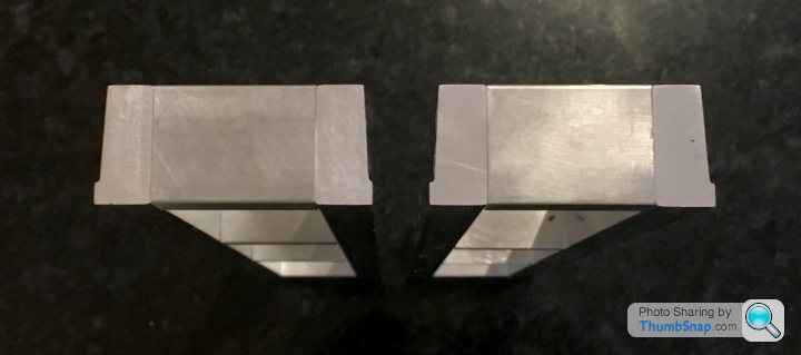
Filed the rounds on the webs:
Test assembled:
Next job is to permanently assemble them with JB Weld, and then machine the taper on the ends, and the top faces.
Marked out the extents of the taper, and carefully made the first cuts:
un u
All seemed fine, so swapped positions and machines the other end to the same DRO z setting:
With the first pair complete, removed the jigs and replaced with those for the opposite hand, and repeated the process:
The time and effort in designing the jigs was worth it - in the end they worked perfectly and the whole process was fairly trivial. A few swirls to flat out, but nothing major.
Final job on the sides was to reduce the plinth widths by 0.65mm:
Finished parts:
Filed the rounds on the webs:
Test assembled:
Next job is to permanently assemble them with JB Weld, and then machine the taper on the ends, and the top faces.
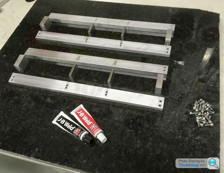
Assembled with JB Weld on the mating faces as a liquid shim. At present everything is snug tight and lightly weighted down on a flat surface. Coated the screws in Vaseline, so hopefully once everything is set true and level I can remove each screw, and fully tighten with retainer:
Next chance I get to work on this will be Wednesday. Hopefully by then the JB Weld will be solid enough to put full load on.
Next chance I get to work on this will be Wednesday. Hopefully by then the JB Weld will be solid enough to put full load on.
anonymous said:
[redacted]
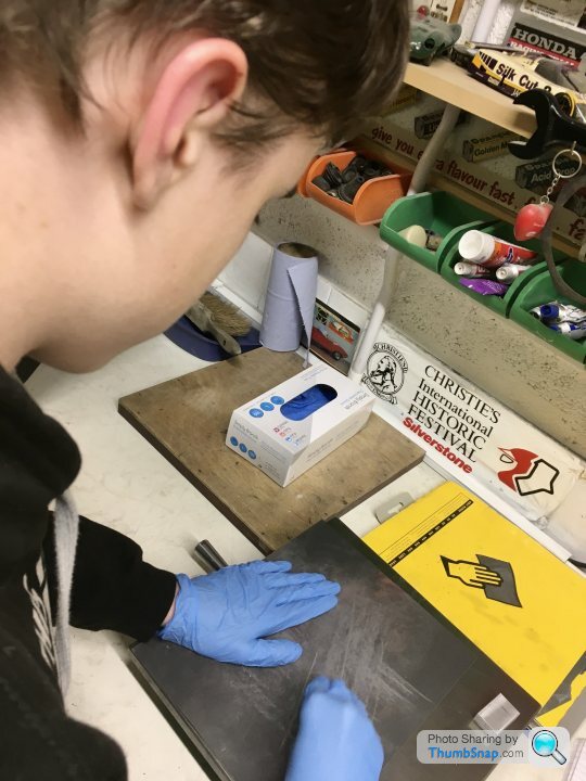
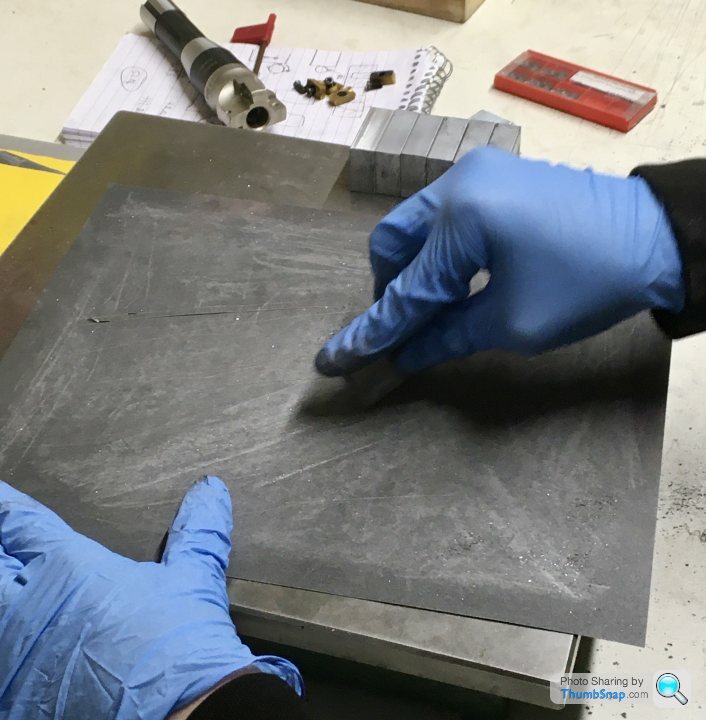
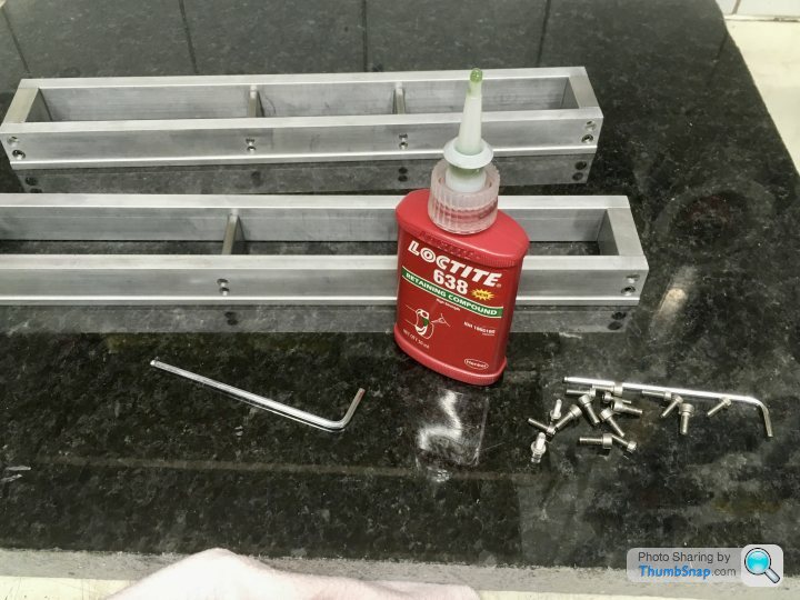
Too kind - thanks. I’m getting a lot of advice from the M.E. forum. I think this has saved me a lot of grief - and a lot of money on castings being replaced by machined assemblies such as these.I got home earlier than expected today, so I spent a couple more hours on the beds. First off, remove and clean the screws, and replace with some retainer added:
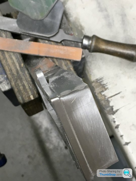
There still appeared to be some residual twist in them, but a couple of passes over some abrasive paper on the granite slab got them perfect. I think the issue may have actually been a couple of small dings on the undersides. Still, the JB Weld gave a smooth finish to the joints, which will hopefully be invisible once painted.
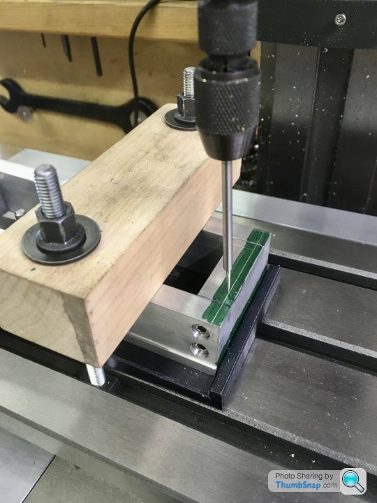
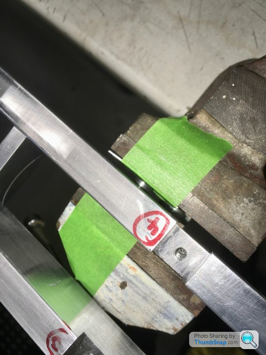
Next up was to clamp to the printed wedge. I used a stop at the back to make sure it wouldn’t get pushed back with vibration:
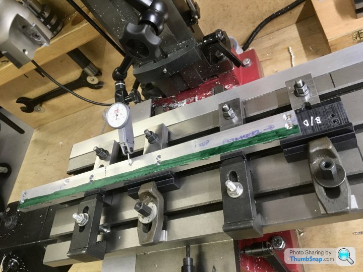
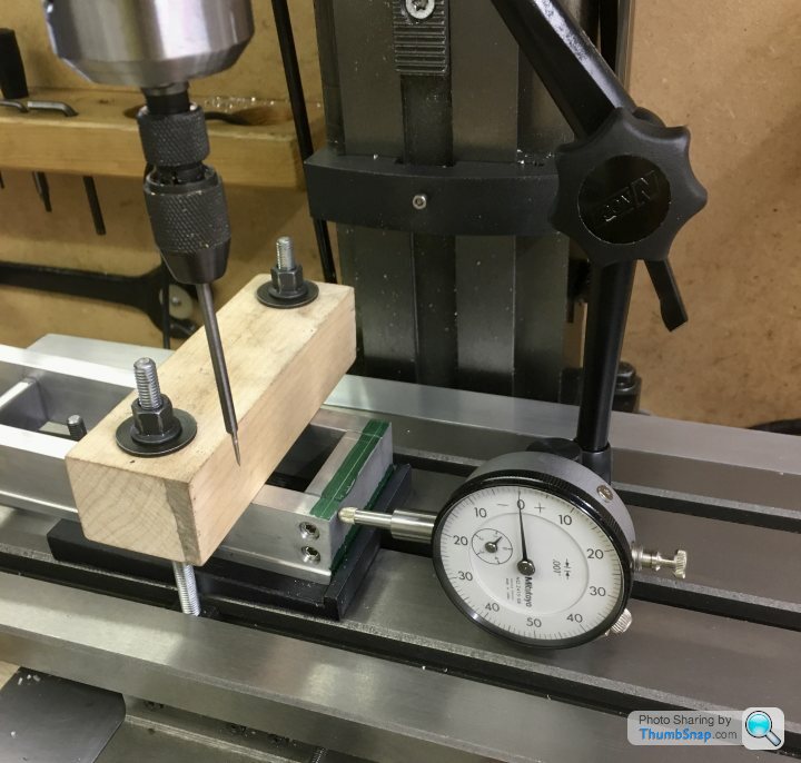
Checked alignment to my mark-out:
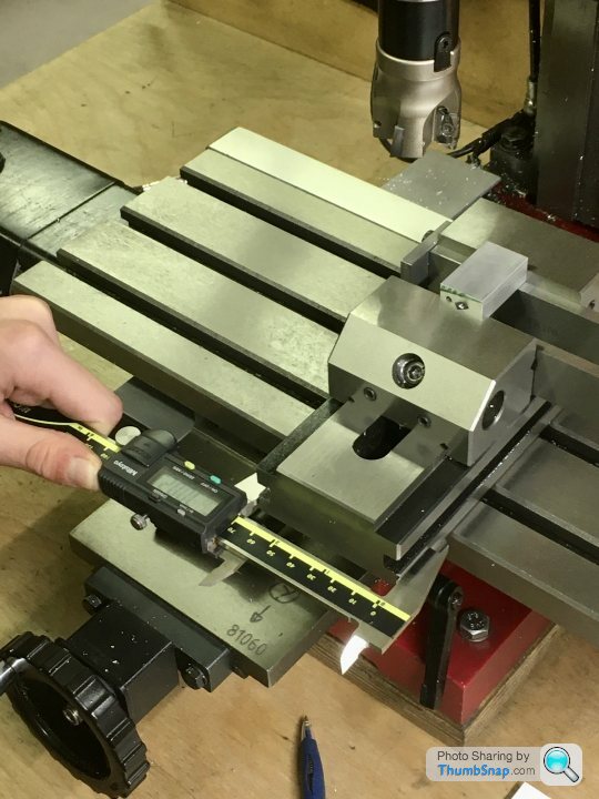
Double-checked with a dial gauge on each end. It was within 0.004”, so good enough for this part:
Made about 10 Z passes with an end-mill, and incremented in X until I got to the line:
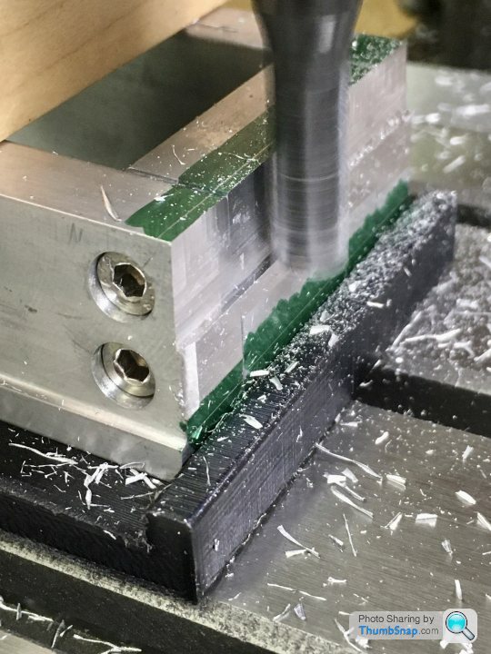
Finished the last couple of mm with the shell mill, which gave me the corner radius:
Still needs the plinth width reducing, which will get rid of the slight discontinuity, but so far so good:
Still another three to do, but enough for tonight.
allegerita said:
I have been breaking my head over these photos the last days, asking myself why you didn’t mount and fix the assembly first and then machine the lower and upper surfaces each in one go? That surely would have saved a lot of work and resulted in the same quality, or am I overlooking something?
Not sure I understand what you mean?I have assembled the frames first, and I’m just finishing the ends.
The lower surfaces don’t need machining because they were ‘set’ on a flat bed - they just needed some very minor flatting with abrasive paper.
The upper surfaces need 0.5 mm skimming off them everywhere, except for where things mount to them - raised pads will be left there. These pads will be given a final very light skim to get them all level right at the end of the process.
allegerita said:
It seems to me you spent a lot of time on minimising tolerances of individual parts, holes and alignment whereas a relatively rough assembly followed by finishing in 1 go would have appeared easier to me.
Not sure about that: How would I assemble them in the first place? I'd still have to drill holes, counterbore them, and then thread corresponding holes in the cross-pieces. All the holes and threads would have to line up so that it assembled with minimal twist. The only way to do this would be to clamp the parts together (clamped on tapered faces just to make it more difficult!), hoping they're aligned in all planes. I'd still need to know where to drill (the middle cross pieces are very thin where the top holes are required), so would still need to work to a mark-out from a drawing at the very least. If I'm doing that, I might as well spend 5 minutes longer and use the DROs and get them perfect.
Even a 1mm length error on each end would then potentially reduce the overall length of the beds by 2 mm once corrected. If the length errors were inconsistent for each bed, then I could correct the overall lengths, but then the thicknesses of the end pieces wouldn't match side to side.
A 1 mm height alignment error at each end would then mean milling at least 1 mm off the entire lower surfaces and 1 mm off the upper surfaces, giving a 2 mm reduction in bed height. Again, if the two beds didn't have exact errors, then one could be higher than the other. OK, they could be corrected to match, but then the lower plinth rim wouldn't be parallel all the way around the base (assuming it was milled in first).
The sections are 1" by 0.5" aluminium (IIRC), and these really define the height and face widths of the base ie what I want to end up with on the finished items.
It may seem a lot of work, but I think for me at least, just working to 0.01 mm accuracy for everything makes it far easier and quicker than trying to correct larger errors for less accurate work. Needing two identical pieces makes it even more important, because for example the crankshaft needs to span both beds, and if the bearings are at different height, it will bind. I really don't want to get into shimming or fettling parts because of non-matching dimensions (at least not excessively). More experienced machinists might be able to do matching assemblies like this by eye, and they turn out right without fettling, but I certainly can't. Once you're into fettling parts like this, it's a tail-chasing exercise that could take days.
Continued with the remaining three end tapers this evening:
Then setup and trimmed the end plinth edges to match the sides:
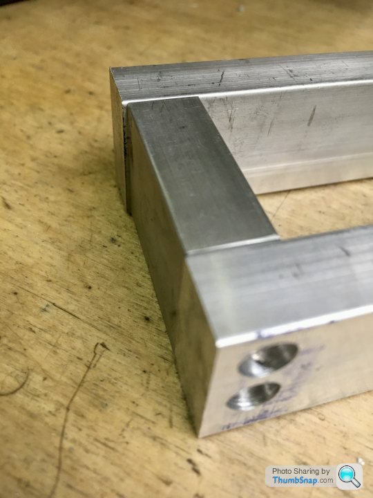
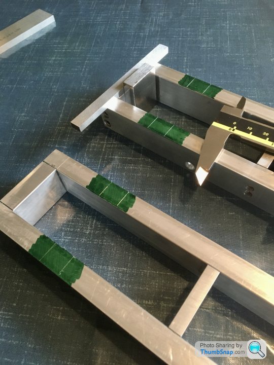
I was happy with the result, with both bases ending up exactly the same overall outside and inside dimensions, and their top faces being within 0.004”:
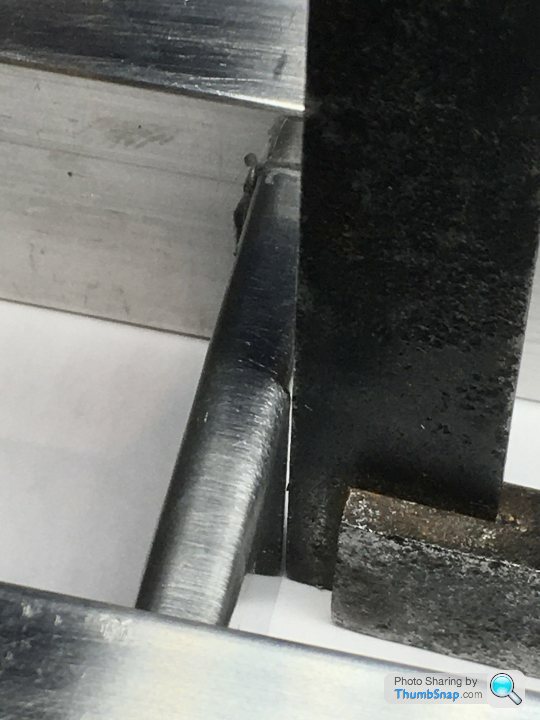
...but when I put them back-to-back, the middle cross pieces didn’t quite match. There was about a 1.5mm discrepancy in the distance between them, side-to-side. Somewhat puzzled, I eventually checked the draw tapers, and found that on one base, both pieces had one vertical side, and one 3 degree side, instead of two 1.5 degree faces. The other base was fine:
As previously mentioned, getting the jigs right was confusing, so we must have ended up mixing the sides up when cutting the second faces.
So with heavy heart, I decided to dismantle the offending side, and re-make the two pieces. I assumed it would be next to impossible to separate them with the JB Weld and the Loctited screws (with their laughably soft caphead hexagons), but I was pretty shocked at how easily everything came undone:
So a bit of a setback, but some progress overall I think.
Then setup and trimmed the end plinth edges to match the sides:
I was happy with the result, with both bases ending up exactly the same overall outside and inside dimensions, and their top faces being within 0.004”:
...but when I put them back-to-back, the middle cross pieces didn’t quite match. There was about a 1.5mm discrepancy in the distance between them, side-to-side. Somewhat puzzled, I eventually checked the draw tapers, and found that on one base, both pieces had one vertical side, and one 3 degree side, instead of two 1.5 degree faces. The other base was fine:
As previously mentioned, getting the jigs right was confusing, so we must have ended up mixing the sides up when cutting the second faces.
So with heavy heart, I decided to dismantle the offending side, and re-make the two pieces. I assumed it would be next to impossible to separate them with the JB Weld and the Loctited screws (with their laughably soft caphead hexagons), but I was pretty shocked at how easily everything came undone:
So a bit of a setback, but some progress overall I think.
Re-made the two spacers. I know what went wrong, I think I got mixed up when swapping them on the 1.5/3 degree jigs, and ended up cancelling the taper on one side and doubling it on the other...
Full disclosure though - on one of them I turned the z-handwheel the wrong way, so that dig-in needed filling with JBWeld. I let that one go because a) it’ll be painted, and b) it’ll be pretty much invisible when the engine is assembled. At least it looks happy:
Also made a start on the mounting lugs which will be screwed into pockets milled into the bases:
Next job will be to drill the strips and radius the ends.
So this is taking a lot longer than anticipated, but I’m wary of cutting corners. The whole thing sits on these beds so they have to be right despite looking pretty simple.
Anyway, drilled and countersunk the strips, and Made a start on milling their recesses. Marked out with verniers first, just as a sanity check for the DROs:
I needed the feet strips to fit precisely to a depth where the 0.8mm fillet in the plinth ended, that way I can replace it with Milliput, hopefully with seamless joints. So pocket depth and strip thickness needed to be identical:
Milling:

Drilling and tapping for the securing screws:
Finished:
Checking the fit:
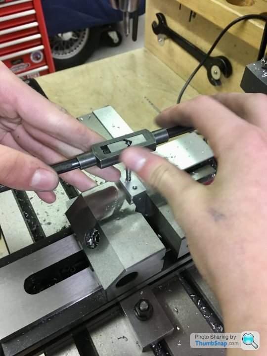
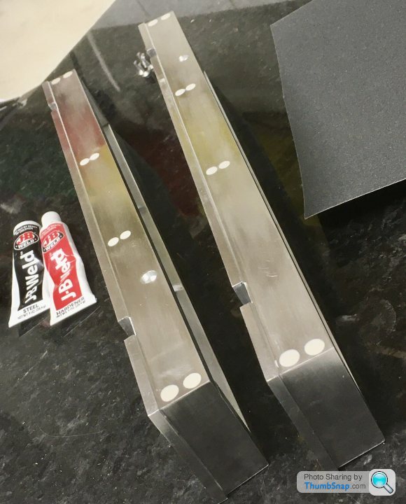
Next job was to radius the ends of the feet. I wanted them precise, and identical, so the boy and I made some 13mm diameter steel filing rollers:

Worked great, so the feet were then split ready for fitting:
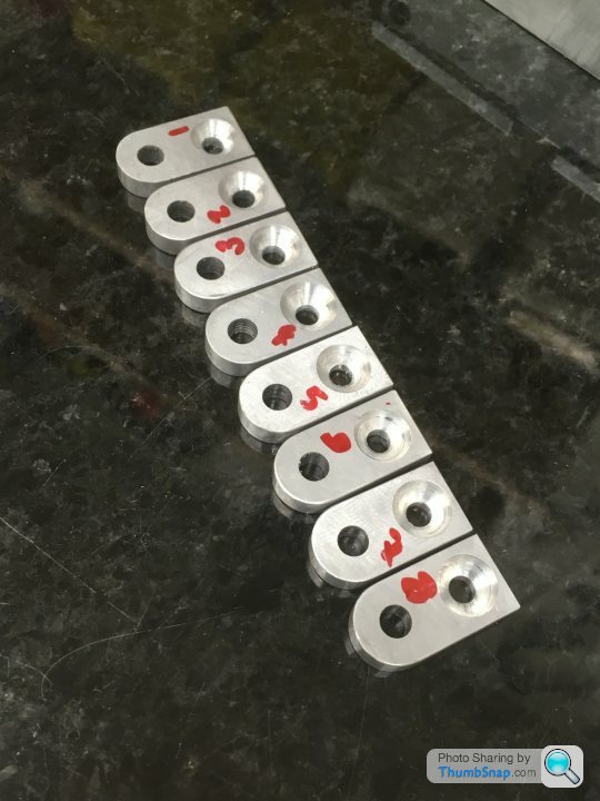
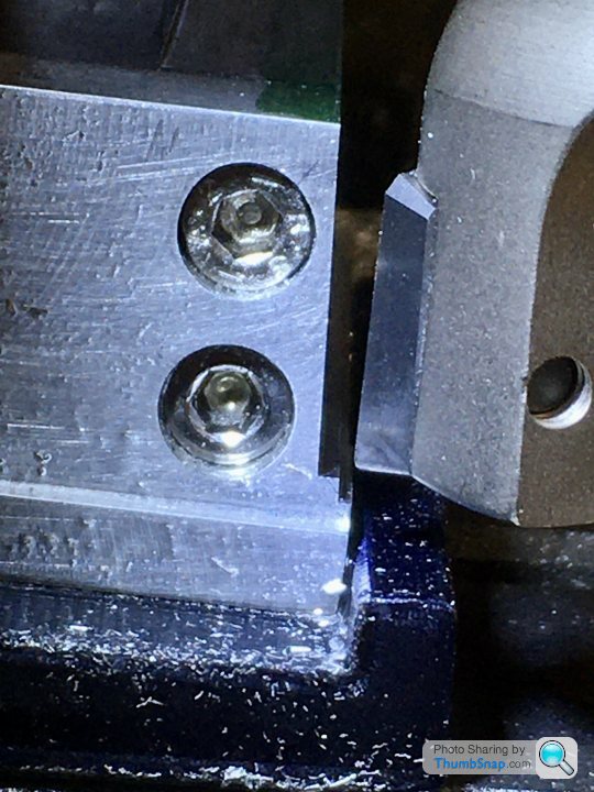
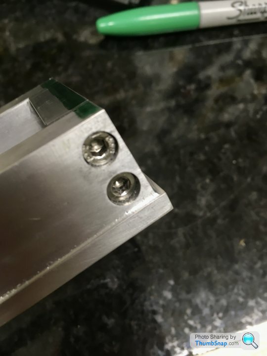
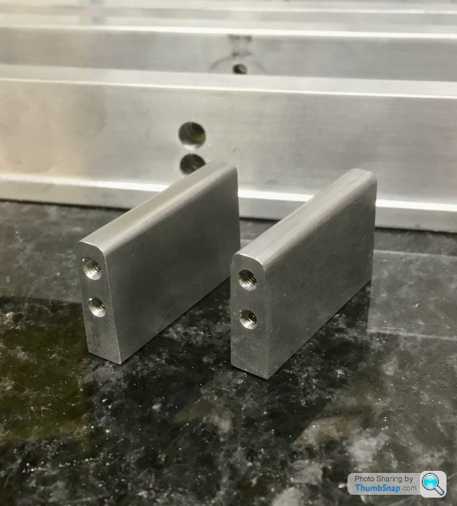
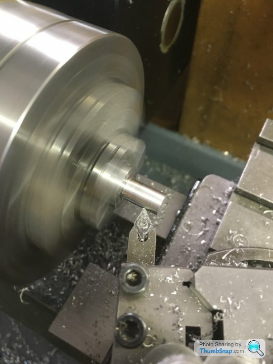
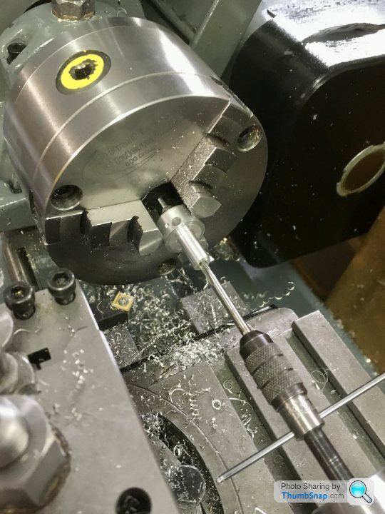
Final job today was to make the throttle bellcrank bosses out of aluminium:

They go in the pre-drilled holes in the bed sides, and will be pressed in with retainer, and then have a fillet of Milliput applied around the joint.
Anyway, drilled and countersunk the strips, and Made a start on milling their recesses. Marked out with verniers first, just as a sanity check for the DROs:
I needed the feet strips to fit precisely to a depth where the 0.8mm fillet in the plinth ended, that way I can replace it with Milliput, hopefully with seamless joints. So pocket depth and strip thickness needed to be identical:
Milling:
Drilling and tapping for the securing screws:
Finished:
Checking the fit:
Next job was to radius the ends of the feet. I wanted them precise, and identical, so the boy and I made some 13mm diameter steel filing rollers:
Worked great, so the feet were then split ready for fitting:
Final job today was to make the throttle bellcrank bosses out of aluminium:
They go in the pre-drilled holes in the bed sides, and will be pressed in with retainer, and then have a fillet of Milliput applied around the joint.
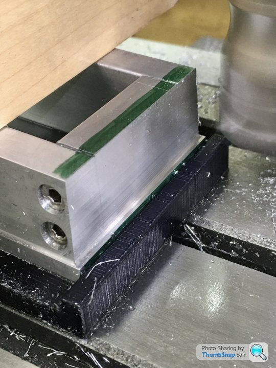
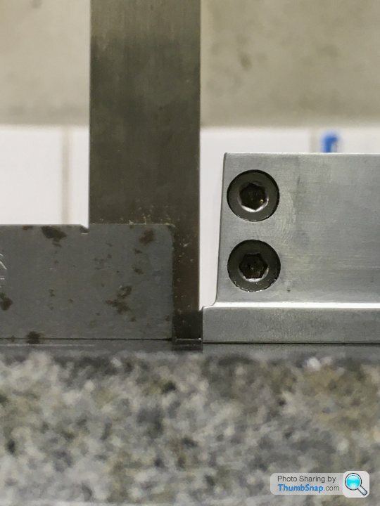
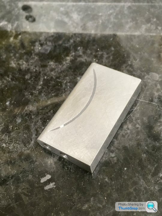
Fitted the lugs , they are a press-fit into their recesses, plus I applied some JB Weld to fill any residual gaps. The excess material on the inner faces will be filed and flatted back:
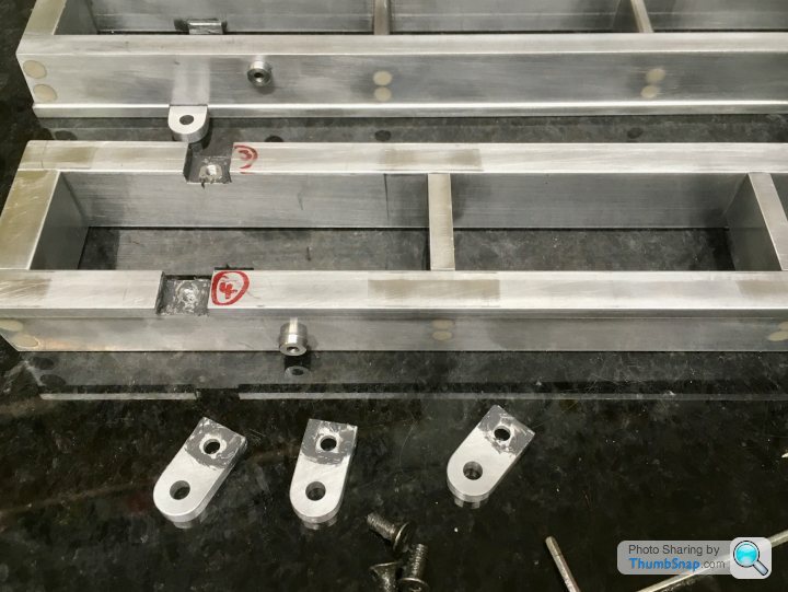
Also fitted the bellcrank bosses in a similar way:
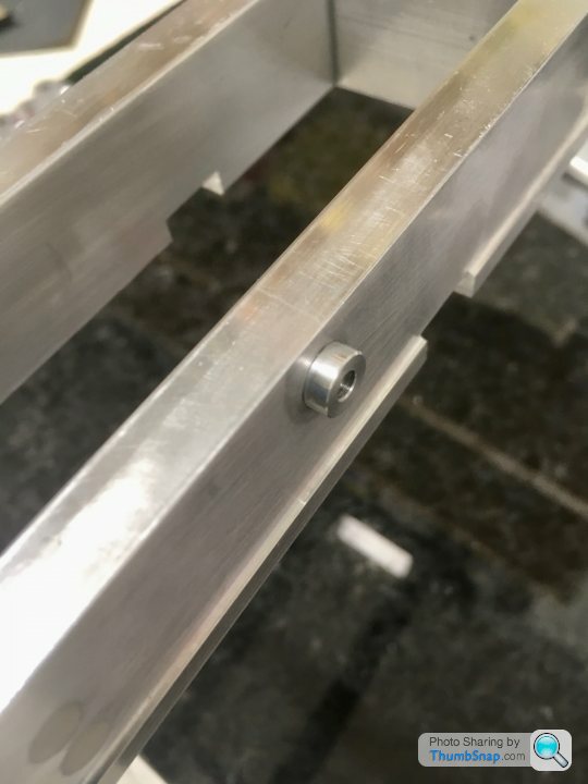
They will have their faces milled back to within a couple of mm of the bed faces when I machine the top pads, then I'll apply a fillet of Milliput all around..
Also fitted the bellcrank bosses in a similar way:
They will have their faces milled back to within a couple of mm of the bed faces when I machine the top pads, then I'll apply a fillet of Milliput all around..
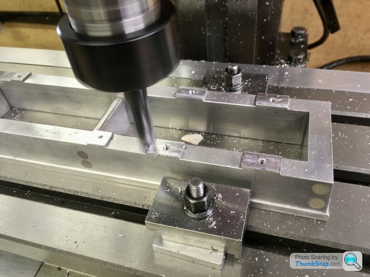
Made a start on machining the mounting pads:
And drilled an tapped the mounting holes at the same time, while everything was aligned:
Also side-milled the throttle boss a fraction narrower than the base footprint:
The mill capacity is too small to do it In one piece, so currently setting up again for the other end:
And drilled an tapped the mounting holes at the same time, while everything was aligned:
Also side-milled the throttle boss a fraction narrower than the base footprint:
The mill capacity is too small to do it In one piece, so currently setting up again for the other end:
Back on this one after a week in deepest West Wales...
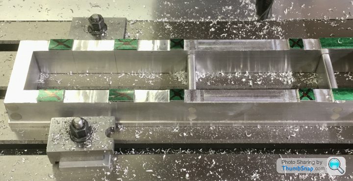
After finishing all the pads (needed four setups), and drilling and tapping all the holes, I set up for skimming the pads:

I took a 0.1 mm cut, again using four setups, but with the z-axis locked:
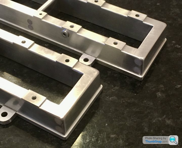
All flat and parallel:
Then began filing radii on all the upper edges:
Now ready for some Milliput in the internal corners:
Hopefully after cleaning with detergent, it will stick...
After finishing all the pads (needed four setups), and drilling and tapping all the holes, I set up for skimming the pads:
I took a 0.1 mm cut, again using four setups, but with the z-axis locked:
All flat and parallel:
Then began filing radii on all the upper edges:
Now ready for some Milliput in the internal corners:
Hopefully after cleaning with detergent, it will stick...
Gassing Station | Scale Models | Top of Page | What's New | My Stuff