Toylander from scratch (metal chassis and body)
Discussion


Jon_Bmw said:
Someone else's viewpoints are always good, especially someone who has been there, done it and got the T-shirt. I'm having to balance the end result over how much time I spend in the garage otherwise I would probably do everything you said. I really wanted full suspension and then I realised that I would need to double the budget and double the time. I hope the kids can use it OK on some of the more car suitable byways on Salisbury Plain.
I'm probably (definitely?) being thick but what advantage does the front swinging really entail if the rear is solid? There must be a bit as the little mobility scooter had the same setup. This could be fairly simply solved, by notching the chassis rail once the rest is all welded up. Not what you'd want on a racer, but...
I can't carry the transaxle across from the mobility scooter for a variety of reasons, the gearing would be wrong, the driveshaft width to narrow and diameter too small.
If Toylander do a twin motor, then surely that is like a non diff axle? Or have they got some clever programming in it? I thought the locked rear axle would be less likely to get stuck, if somewhat unsympathetic to general turning principles.
The 205 that you can see in the background of one of the pictures actually has a plate LSD which, whilst still technically a differential, has a very aggressive lockup so I am used to the scrubbing/banging and embarrassing passer-by looks. That works ok and is FWD.
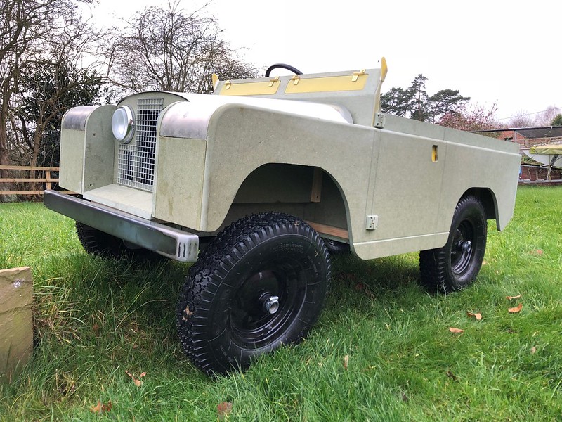
The wheels are 12" vs 14.75 from toylander, the thing that is hurting it, is I am scaled up by approx 20% I guess. I don't really know as I don't have toylander plans and it seemed unjust to buy them and copy everything! I actually think series 1 land rovers look a bit odd (sorry! ) with the wheels looking massively oversized for the vehicle, but understand why they did it.
I'm still tempted to cut the uprights down and then redraw the panels. Anyone got some spare enthusiasm in a jar?
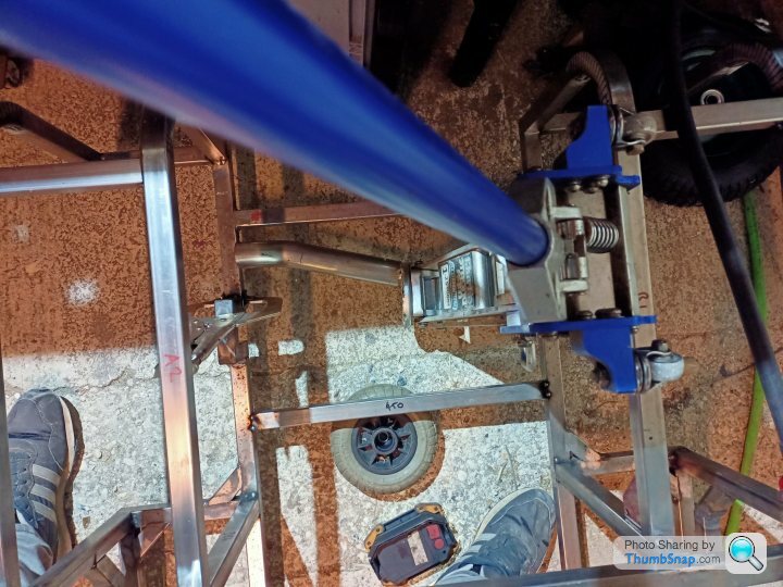
If you have something with absolutely no suspension, it's going to have a wheel in the air unless it's on a totally flat surface. If the rear axle is unsprung and mounted directly to the chassis, but the front axle can swing, the vehicle will still maintain contact on all four wheels. Obviously you don't need any springs on the front as long as the rear axle is fixed. Look at this picture from my build thread, and then imagine how it would work with a go-cart with zero wheel travel...lots of wheel waggling!I'm probably (definitely?) being thick but what advantage does the front swinging really entail if the rear is solid? There must be a bit as the little mobility scooter had the same setup. This could be fairly simply solved, by notching the chassis rail once the rest is all welded up. Not what you'd want on a racer, but...
I can't carry the transaxle across from the mobility scooter for a variety of reasons, the gearing would be wrong, the driveshaft width to narrow and diameter too small.
If Toylander do a twin motor, then surely that is like a non diff axle? Or have they got some clever programming in it? I thought the locked rear axle would be less likely to get stuck, if somewhat unsympathetic to general turning principles.
The 205 that you can see in the background of one of the pictures actually has a plate LSD which, whilst still technically a differential, has a very aggressive lockup so I am used to the scrubbing/banging and embarrassing passer-by looks.
That works ok and is FWD.The wheels are 12" vs 14.75 from toylander, the thing that is hurting it, is I am scaled up by approx 20% I guess. I don't really know as I don't have toylander plans and it seemed unjust to buy them and copy everything! I actually think series 1 land rovers look a bit odd (sorry!
) with the wheels looking massively oversized for the vehicle, but understand why they did it. I'm still tempted to cut the uprights down and then redraw the panels. Anyone got some spare enthusiasm in a jar?
Toylanders have a solid axle, but each wheel is free to rotate on it. There's nothing clever on the twin motor setup, however when the steering wheel is turned, and the outside driven wheel needs to turn faster, it's able to do this, there's less load on it, it's happy to spin faster to "keep up" with the axle. I really think you need to look at the transaxle setup...if you look at my build the wheels are not mounted on the transaxle, the wheels are on their own static beam rear axle mounted below the transaxle, with chain drive down. It does not matter about the width of the transaxle or the gear ratios if you go chain drive down from the transaxle to the wheel axle...you get to choose your ratios anyway depending on how many teeth your sprockets have.
It feels like you are coming at this from a track car perspective, small wheels, low ground clearance, "LSD" axles. What you are actually building is an off-roader...nothing to do with the Land Rover shape, it's how you intend to use it. Some full size off roaders use lockable diffs, usually manually activated for the gloopy bits, and then released. (that said, my 110 has open diffs as they all do from the factor and is very capable off road) You can't get the steering lock you need with solid locked axles. Bear in mind your little one will be going round in tight circles, doing 3 point turns, I just don't think it will work unless it's on the slippiest of surfaces. I have a feeling that on anything with any grip, the vehicle will just plough on with very heavy steering (assuming your little one can hold it...remember you are talking half a turn lock to lock) with monumental understeer. I guess if you've done any karting, think about trying to drive a cart with very little power in lots of tight turns...it's going to be really, really hard work. No suspension, and no diff is fine on something that has power to unstick the rear and takes wide turns on flat ground, but just won't suit a Toylander style vehicle at all IMHO.
But I'll say it again, you've done some great work, and it's not too late at all to engineer in a swing axle and a transaxle. There's stacks of room in your chassis.
Edited by Hard-Drive on Monday 15th November 18:04
I think I now understand how your axle works and I can see the benefits. Ironically it's a lot more simplistic. Does it not get stuck wheel spinning ever? I guess it's overall weight is quite low and as long as you have a bit of momentum it's probably fine.
Trying to get the swinging front axle is something I will try and do. The live axle I guess offsets the lack of suspension at the rear, my main concern was wheel spinning one wheel on uneven ground.
The comment about the 205 was purely a reference that a fixed axle does work with a different set of drawbacks. I don't think I'm under any illusions that it's perfect but I don't think my lads are going to be rockclimbing the thing either. Mostly flat byways and the garden.
Interesting point about the weight of the steering, something else I hadn't really considered. If I offset the motor and it all goes to s t I can always mount another couple of pillar bearings and disc cut the live axle. Nothing like a bodge with an angle grinder.
Thanks for all the feedback. More time designing next time and less cutting.
Trying to get the swinging front axle is something I will try and do. The live axle I guess offsets the lack of suspension at the rear, my main concern was wheel spinning one wheel on uneven ground.
The comment about the 205 was purely a reference that a fixed axle does work with a different set of drawbacks. I don't think I'm under any illusions that it's perfect but I don't think my lads are going to be rockclimbing the thing either. Mostly flat byways and the garden.
Interesting point about the weight of the steering, something else I hadn't really considered. If I offset the motor and it all goes to s
t I can always mount another couple of pillar bearings and disc cut the live axle. Nothing like a bodge with an angle grinder. Thanks for all the feedback. More time designing next time and less cutting.
Trust me it’s not light! I seem to remember it’s about 80kg. It’s remarkably good off road and very rarely gets stuck. Weight is good, it gives traction. Have a look at the videos I linked in my thread to see it in action.
Wheel size, suspension, ground clearance and tyre pressure/contact patch, and approach angle (dictated by the front bumper) will make the biggest difference off road. Bigger wheels roll over things better and don’t get stuck in hollows. They also allow you to “air down” and loose ground clearance but still have enough to keep driving. The solid axle really will just be a hindrance in all but the most extreme boggy conditions. That’s why something like a 2wd drive open diff Beetle is good off road and was the basis for beach buggies, sand rails and rally cars…tall wheels, good ground clearance, short overhangs (when chopped) and lots of weight over the back axle. Ditto trials cars…you don’t see them with low bumpers and no suspension.
Good luck with the build and keep the updates coming! :thumb up:
Thick OP here...
With the swinging front axle (central bolt method), with the driver offset what stops it naturally leaning over? The same for going round corners.
What travel at the wheel end do you have Hard drive. I am thinking about 100mm.
Am I overthinking it, or would it be better with some valve springs or something to try and offset the weight of the driver but allow for travel when hitting bumps. Can you tell I am not an engineer, Cad guy or fabricator yet? Just wait until we get to the electronics
Good question…because the rear axle has no travel and is rigid, the car won’t lean/flop over. It just allows the front (and therefore the rear) to “track” the ground. If both axles were swinging axles, then the body would flop around uselessly. The rear axle must be fixed, it’s just like a tractor.
Remember there’s no actual “suspension”. If you hit a kerb straight on there’s no movement as the axle cannot go up and down in relation to the vehicle. It only swings…if one wheel is going up, the other has to go down to compensate.
Remember there’s no actual “suspension”. If you hit a kerb straight on there’s no movement as the axle cannot go up and down in relation to the vehicle. It only swings…if one wheel is going up, the other has to go down to compensate.
Edited by Hard-Drive on Tuesday 16th November 12:53
Brill, thanks for that. Without first hand experience or these things it's hard to appreciate what actually happens in the real world. I don't have any vehicles to poke about with.
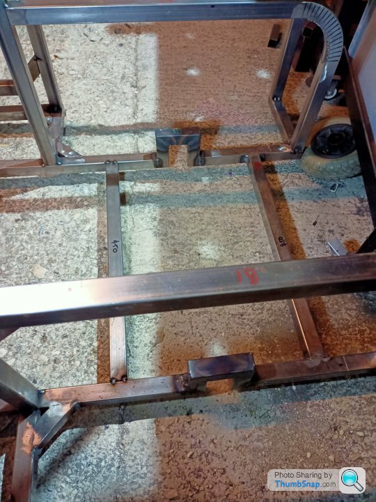
So to accommodate the swinging axle and keep the approximate ride height I have I need to notch the chassis rails.
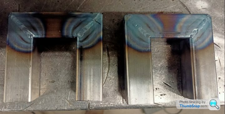
I knobbed these up at work in my half an hour lunch break. Benefits, chop saw thats good for 45's, TIG weld plant. Drawbacks, all the experts piss taking my welding. Ha.
I will use a couple of strengtheners each side of the uprights to try and support them better. Less than an ideal solution, but "it'll do."
I think I will drop the front wing box sections curing the issue of having to mount an additional bulkhead and making it slightly more authentic. The rear I will see how we get on....
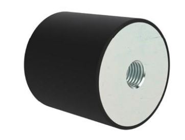
I did some basic trig earlier and calculated that I needed 54mm clearance in the chassis rails to get 100mm of upward movement. I've gone bigger than that so I can stick a rubber dobber in there as a bump stop and tune it slightly.
I've checked the clearance to the wing panels and it just clears (theoretically). I need to remember to alter the wing panels in cad to match the "dropped" front end but maintain the wheel arch height. That is definitely something I'm going to forget to do!
"It'll do" is the new project Moto!
So to accommodate the swinging axle and keep the approximate ride height I have I need to notch the chassis rails.
I knobbed these up at work in my half an hour lunch break. Benefits, chop saw thats good for 45's, TIG weld plant. Drawbacks, all the experts piss taking my welding. Ha.
I will use a couple of strengtheners each side of the uprights to try and support them better. Less than an ideal solution, but "it'll do."
I think I will drop the front wing box sections curing the issue of having to mount an additional bulkhead and making it slightly more authentic. The rear I will see how we get on....
I did some basic trig earlier and calculated that I needed 54mm clearance in the chassis rails to get 100mm of upward movement. I've gone bigger than that so I can stick a rubber dobber in there as a bump stop and tune it slightly.
I've checked the clearance to the wing panels and it just clears (theoretically). I need to remember to alter the wing panels in cad to match the "dropped" front end but maintain the wheel arch height. That is definitely something I'm going to forget to do!
"It'll do" is the new project Moto!
Your welding looks excellent!! Mine is hopeless by comparison, I usually need to do about five minutes with the chipping hammer and grinder for every one minute with the MIG welder!
I've just checked my lad's TL and there's about 110mm of wheel articulation in total, so from the level position that's roughly 55mm up and 55mm down. I'm not sure you mean 100mm total (as in very similar to ours) or 100mm each way, 200mm in total. I would strongly advise against this as it will be more likely to tip over.
Also bear in mind I fitted bigger wheels, and have about 260mm of clearance under the front bumper. Basically, if you have smaller wheels and less ground clearance, you'll also want less travel.
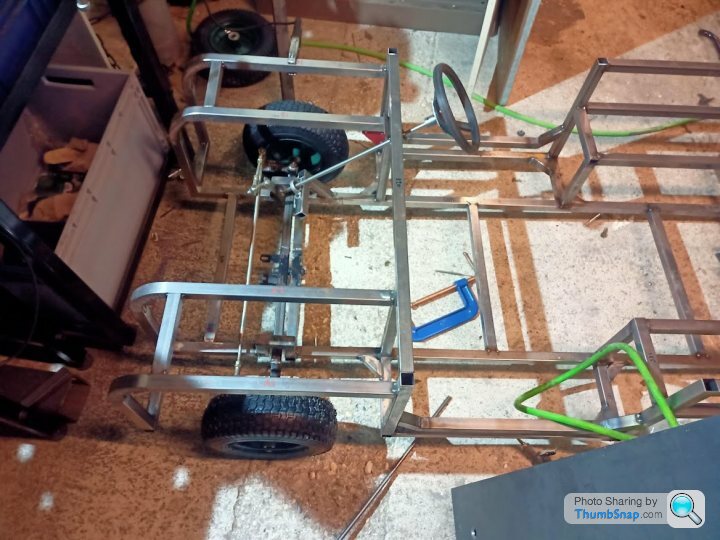
So 3 hours, predominantly procrastinating, in the garage last night ended up with the following progress:
Dropped the front wings down by 2" and gained the bulkhead for the W/screen to mount to. It didn't take too long. Added in supports for the main tub, designed in a way so that they arn't going to get too much in the way of the doors, if I decide to have doors.
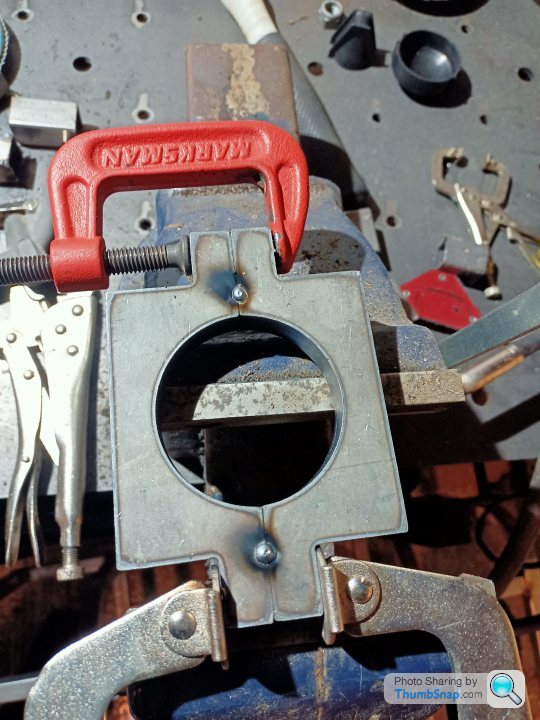
Then notched the chassis leg for the tractor style front axle. The chassis is under a bit of tension so when you cut it the rails wonder quite a bit and that was with some temporary supports near the area as well.
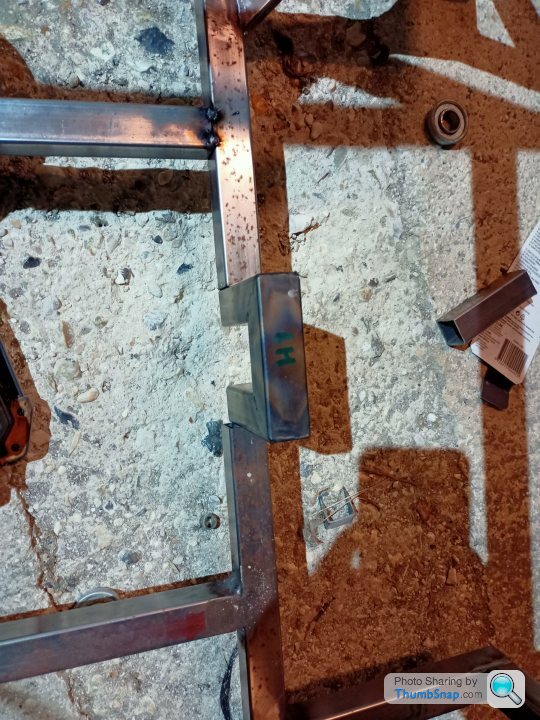
Figure out which side has moved, then bodge:
All welded up:
I will weld the front cross bar under the chassis now, then bolt the swinging axle to that. It will swing into those nice notches (fingers crossed!) and the swing angle I can tweak by fitting a couple of rubber dobbers to the notched part on a bolt:
Also, I am starting to think about the steering column. It will probably be a couple of pillow bearings one near the bulkhead and another near the tie rod with a UJ to take out any minor misalignment:
Until next time.
Dropped the front wings down by 2" and gained the bulkhead for the W/screen to mount to. It didn't take too long. Added in supports for the main tub, designed in a way so that they arn't going to get too much in the way of the doors, if I decide to have doors.
Then notched the chassis leg for the tractor style front axle. The chassis is under a bit of tension so when you cut it the rails wonder quite a bit and that was with some temporary supports near the area as well.
Figure out which side has moved, then bodge:
All welded up:
I will weld the front cross bar under the chassis now, then bolt the swinging axle to that. It will swing into those nice notches (fingers crossed!) and the swing angle I can tweak by fitting a couple of rubber dobbers to the notched part on a bolt:
Also, I am starting to think about the steering column. It will probably be a couple of pillow bearings one near the bulkhead and another near the tie rod with a UJ to take out any minor misalignment:
Until next time.
There has been minimal progress over the last few weeks. I blame the miserable weather and cold garage, but its probably just me lacking enthusiasm.
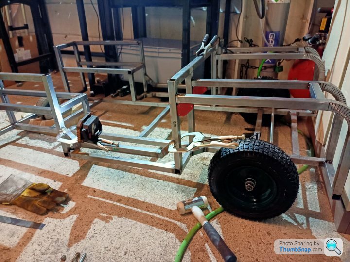
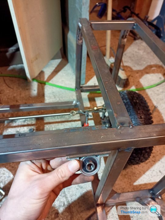
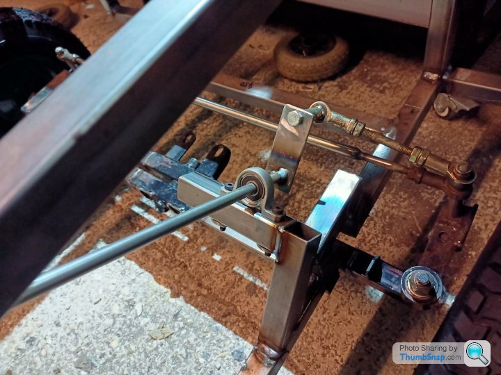
I welded up the tractor axle support bar and bolted that up. I had to extend the mobility scooter King pin so the steering arm misses my chassis notches. They still need slightly taller spacers but I didn't have any M8 x 130 bolts kicking around. Who does!
You can also see the steering column is test fitted there. I need to triangulate the bottom pillar bearing support but it actually works.
On larger axle articulation, the steering tie rods contact the chassis notches, so the increased spacers should help there. I am yet to fit the rubber dobbers to limit the travel.
3D printed steering wheel will probably be replaced by a metal/3D printed hybrid to offer more strength, but it might do a test drive. Its better than a mole grip right?
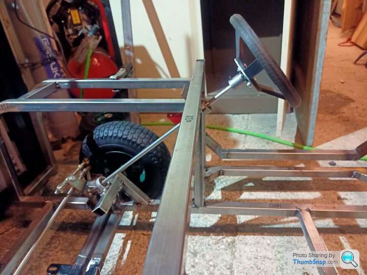
A bonus of the pillar bearings and rose joints on the steering rods is that you can fine tune the height of the column by around 100mm and then lock it off using the grub screws on the bearings. It might come in useful as the kids get older. I won't pretend that I designed that in...
The rear axle drawing is still with my machinist colleague, some normal paid work is getting in the way. WTF?
The rear axle would be nice to design the motor mount and other gubbins in that area, but in the spirit of this project I'll have to do without.
So, laser cut supports:
Tack them for the drilling the through holes:
This looks safe, safety squint on:
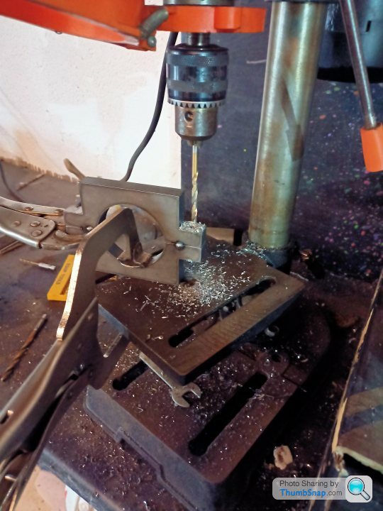
3mm plate with 12mm oversize holes in, then bish, bash, bosh I welded the mounts onto it. Ideally I could have turned the welder up some more, but I blew a fuse last week with it on its max setting, so I laid some horribly cold welds down.
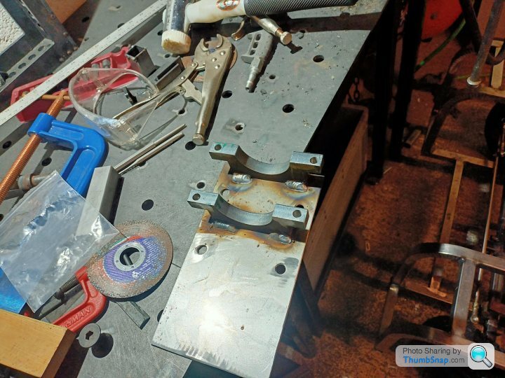
It would have been nice if the holes were central, but as my dad says, "you can't have everything." Much like a clean work surface.

The 12mm holes in the plate should allow some adjustment in X and Y to adjust chain slack. Big penny style washers will be used with M8 bolts I reckon.
More adjustments are probably likely when I get the rear axle from the machinist. That'll do.
I welded up the tractor axle support bar and bolted that up. I had to extend the mobility scooter King pin so the steering arm misses my chassis notches.
They still need slightly taller spacers but I didn't have any M8 x 130 bolts kicking around. Who does!You can also see the steering column is test fitted there. I need to triangulate the bottom pillar bearing support but it actually works.
On larger axle articulation, the steering tie rods contact the chassis notches, so the increased spacers should help there. I am yet to fit the rubber dobbers to limit the travel.
3D printed steering wheel will probably be replaced by a metal/3D printed hybrid to offer more strength, but it might do a test drive. Its better than a mole grip right?
A bonus of the pillar bearings and rose joints on the steering rods is that you can fine tune the height of the column by around 100mm and then lock it off using the grub screws on the bearings. It might come in useful as the kids get older. I won't pretend that I designed that in...
The rear axle drawing is still with my machinist colleague, some normal paid work is getting in the way. WTF?
The rear axle would be nice to design the motor mount and other gubbins in that area, but in the spirit of this project I'll have to do without.
So, laser cut supports:
Tack them for the drilling the through holes:
This looks safe, safety squint on:
3mm plate with 12mm oversize holes in, then bish, bash, bosh I welded the mounts onto it. Ideally I could have turned the welder up some more, but I blew a fuse last week with it on its max setting, so I laid some horribly cold welds down.
It would have been nice if the holes were central, but as my dad says, "you can't have everything." Much like a clean work surface.
The 12mm holes in the plate should allow some adjustment in X and Y to adjust chain slack. Big penny style washers will be used with M8 bolts I reckon.
More adjustments are probably likely when I get the rear axle from the machinist. That'll do.
I had 2 weeks off over Christmas, so as expected, zero progress with the toylander!
I took the oldest to Haynes motor museum over the holiday and they had a series 3 there which I took a few photos of as a bit of a guide. The good thing with a series 3 is that the rear tub is higher than the front wings! So I'm now aiming for that as it matches more closely what I have done so far. Sorry landrover lovers!
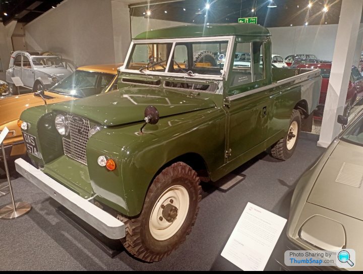
Getting that radius at the top of the panels especially on the front wing could be a challenge. Originally I wasn't going to bother and just have flat laser panels but after seeing the real thing it would look a lot nicer. I can always extend out the year it's ready, right?
This is the panel and area that will be most difficult. It probably isn't difficult if you are a fabby, but as we know I'm not!
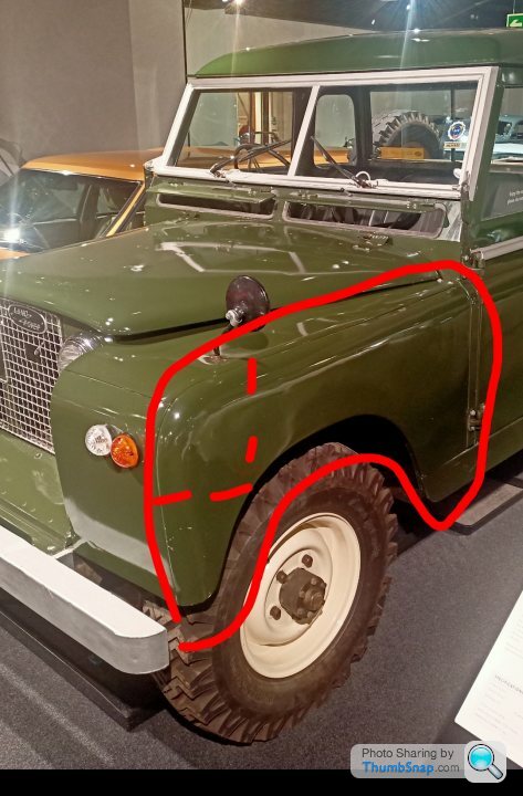
In the dashed area I am thinking of making up a 3d printed press tool and seeing what happens. Shrinking the material in this area is probably going to be a challenge, so I'll suck it and see. Then once I've made a mess give it to one of the fabbies at work!
I need to make up a bench mounted folder so that I can clamp some tube to that to bend the metal around it. Being a parent to two younguns mean you start scribbling down silly ideas whenever you have a spare minute or else they get lost in brain mush, this happened to be in the bath after a long day with them both, so probably lots of errors. They are just ideas so go gently!
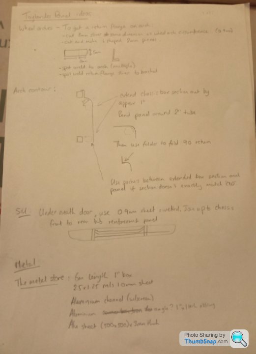
So I think I'll try and mock some parts up, make the metal folder and then order some metal parts. The aluminium on the list is to do the channel on the top of the rear tub and to make the w/screen. I'll try and find some acrylic that will slot in the channel. The 3mm might become 5mm to make the windscreen brackets.
So in summary;
Hand make all panels rather than laser them, because why make life easy!
I took the oldest to Haynes motor museum over the holiday and they had a series 3 there which I took a few photos of as a bit of a guide. The good thing with a series 3 is that the rear tub is higher than the front wings! So I'm now aiming for that as it matches more closely what I have done so far. Sorry landrover lovers!
Getting that radius at the top of the panels especially on the front wing could be a challenge. Originally I wasn't going to bother and just have flat laser panels but after seeing the real thing it would look a lot nicer. I can always extend out the year it's ready, right?
This is the panel and area that will be most difficult. It probably isn't difficult if you are a fabby, but as we know I'm not!
In the dashed area I am thinking of making up a 3d printed press tool and seeing what happens. Shrinking the material in this area is probably going to be a challenge, so I'll suck it and see. Then once I've made a mess give it to one of the fabbies at work!
I need to make up a bench mounted folder so that I can clamp some tube to that to bend the metal around it. Being a parent to two younguns mean you start scribbling down silly ideas whenever you have a spare minute or else they get lost in brain mush, this happened to be in the bath after a long day with them both, so probably lots of errors. They are just ideas so go gently!
So I think I'll try and mock some parts up, make the metal folder and then order some metal parts. The aluminium on the list is to do the channel on the top of the rear tub and to make the w/screen. I'll try and find some acrylic that will slot in the channel. The 3mm might become 5mm to make the windscreen brackets.
So in summary;
Hand make all panels rather than laser them, because why make life easy!
I feel like an insane person talking to myself, but anyhow, its a good log of my mental breakdown.
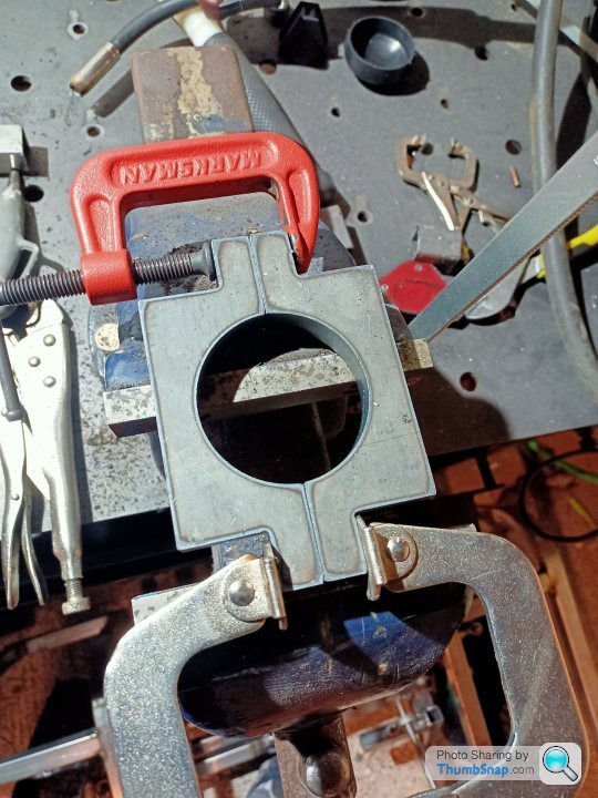
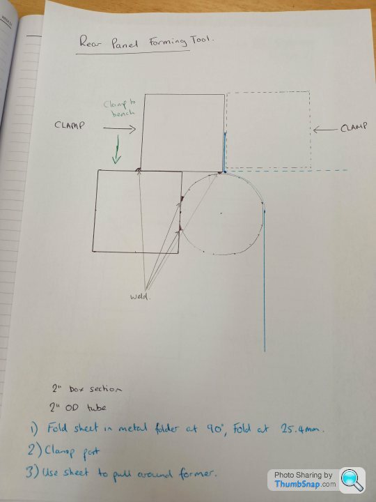
To the rear arch contour and how to form it, 5 minutes with a pen and paper;
Test piece made up. I made two attempts, with a bit of heat on the bend radius it forms very well although naturally the real panel will be a lot wider so may not form as well:
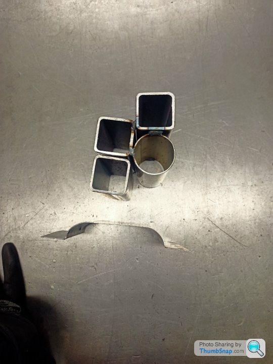
If anyone has detective eyes, they will notice that is 40mm box and 45mm tube which is why it looks a bit odd. I later found some 50box and tube and the results were better with no heat needed. Across the full panel I think a bit of heat will be required to encourage it without the need for smashing it with a hammer.
The front arch with the compound curve is definitely going to be more difficult to make the tool but I have a fall back plan for that when plan A doesn't go very well.
To the rear arch contour and how to form it, 5 minutes with a pen and paper;
Test piece made up. I made two attempts, with a bit of heat on the bend radius it forms very well although naturally the real panel will be a lot wider so may not form as well:
If anyone has detective eyes, they will notice that is 40mm box and 45mm tube which is why it looks a bit odd. I later found some 50box and tube and the results were better with no heat needed. Across the full panel I think a bit of heat will be required to encourage it without the need for smashing it with a hammer.
The front arch with the compound curve is definitely going to be more difficult to make the tool but I have a fall back plan for that when plan A doesn't go very well.

Thanks guys, I'm glad you are reading it and it's made me conscious that I should contribute to the threads on here that I get enjoyment out of but don't comment. Ref doing it out of MDF, 100% it would have been easier. Not only is the material easier to work with but you are working to a well developed plan. I've lost count of the foul ups made so far, and there are lots to come I am sure.
I mainly did it as a challenge to myself that the kids will then benefit from. When it's done hopefully i'll be proud of it whilst watching the kids get enjoyment out of it too. I didn't have the skills, and still don't have the skills but it is continuing to be a good challenge.
The scope is continuing to evolve and make it more and more challenging the more I do. It is stretching me but I think I need a challenge in life or else I tend to get bored.
As nothing is defined, written down, planned I normally come up with a few poor ideas and canvass opinion from colleagues at work or or here. I'm sure it is what Boris does, leak some stupid statements or ideas to the public and then completely change his strategy when everyone disagrees with him.
Panel work:
Now I feel confident that I can make the radius on the rear panel, I'm going to try and hammer a return on the wheel arch cut out. As I am going to make the panels by hand I need a good cutting strategy for the metalwork so that I don't have a lot of dressing work with a grinder.
At the moment I am thinking either buying an air nibbler or using a jigsaw. I will probably make a wooden guide to follow and it would be nice if I could use that wooden guide to hammer the return on the wheel arch as well but I think I might need two guides. I need to get the tool first and work out what the cutting guide might look like. My fall back plan is to do a 1-1 drawing in cad, print it on a plotter at work and then cut it out using that.
Front panels, ideally I want a return on the wings and bonnet/front panels. This is definitely going to be a challenge with lots of shrinking and stretching of material to be done. As with most of this project, I have never done any of that before either! The returns on the inside wing to front bonnet panel won't really show but it would look right if I make them that way rather than having two raw edges of material butted up to each other. So for these I can probably make some slivers in the material and either weld them back up or leave them as they won't be visible.
Steering Wheel:
As mentioned before it is 3d printed and therefore weak between the spokes and the rim/boss. Rather than remake a hybrid metal/printed one I have some carbon fibre sheet that I got a while back to understand the material. So I will try and skin the steering wheel with real carbon to add some strength. I suspect I'll make a bit of a hash of it, so it'll probably be sanded down and painted over to cover the nasties. It would probably look a bit odd if I left the raw carbon in a 60/70's land rover model. On that subject, I'm an idiot, it is a series 2 that I saw in the museum, so that's what I am aiming to make...
eccles said:
Could you make an MDF front wing 'buck' then mould a fibreglass front wing skin to fasten to your chassis frame? Or are you wanting it to be all metal?
Or even just panel beat some ally sheet over a former? The ally fuel cap surround and corner panels on mine started off as flat ally sheet and I was surprised what I managed to achieve...and bear in mind I drive a PC and spreadsheets for a living, I'm sure you could do a better job with your experience/facilities...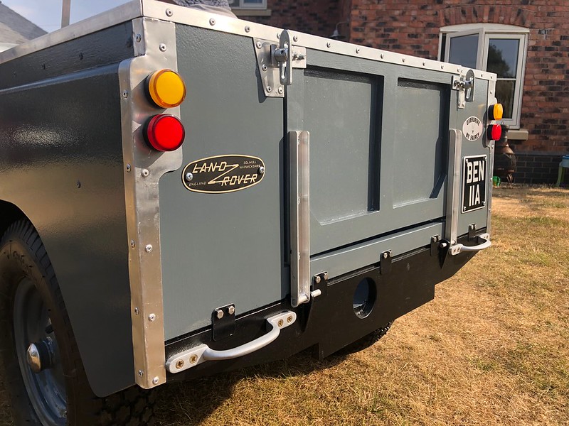
Its a good idea, and one that I thought about for a while. I would have probably made a combined wooden and 3d printed buck and then tried making it from the CF I have lying around. I really want it to be metal though, partially stubbornness and also wanting to learn a bit more about hand forming thin gauge metalwork. My brother has a rusty classic Impreza, and perhaps a bit of metalwork on this will give me confidence to weld his up for him...
Ref the front wings, I have got our tube benders at work to bend up some 90 degree 50mm pipes for me in a similar radius to my chassis profile.
Plan A - weld 50mm box to bend straights and attempt to hammer form front wing around that tool (concerns - tucking of material and material wanting to 'fall' into the gap between bend and welded box section). Some of those I can mitigate and probably all of them with enough time!
Plan B - Use bends, section them into 4 and take radius and weld onto sheet metal (concerns - panel warping)
Plan C - Only use bend section and do the same as B. Use rear radius tool in above posts to do straight sections on the wing to minimise welding distortion.
To further complicate it I would ideally like to put a return/flange on the wing so it looks right where it butts up to the wing/bonnet panel.
That would be straight forward enough on the straight parts, but the radius will cause some issues I am sure. Issues on top of issues, that is what everyone is here for right!
Edited to add: I have just seen your post Hard Drive. You are grossly overestimating my experience and our facilities!
Edited by Jon_Bmw on Monday 10th January 11:07
Great work, really interesting to see. I have seen another fabricated one somewhere certainly not for the faint hearted.
I have just started accumulating parts for my build, driving to toylander plans mostly but going with a chain drive from a mobility scooter and detailing it where I can.
Hard-drive, love some of the bits you have done with rivets etc. are they real in the MDF.
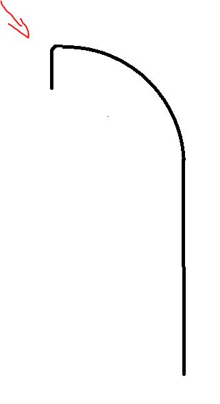
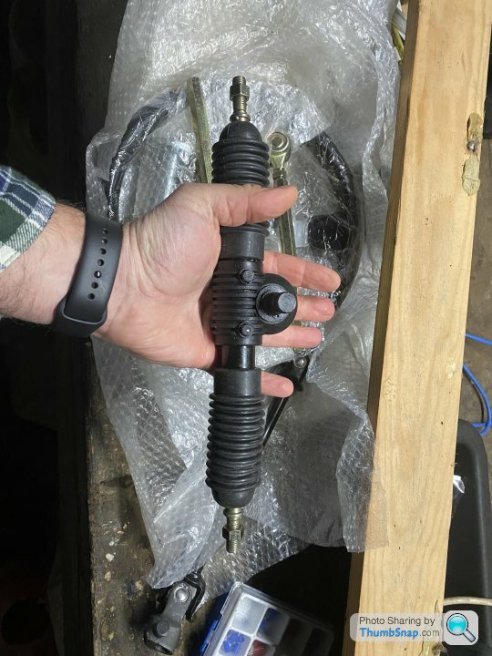
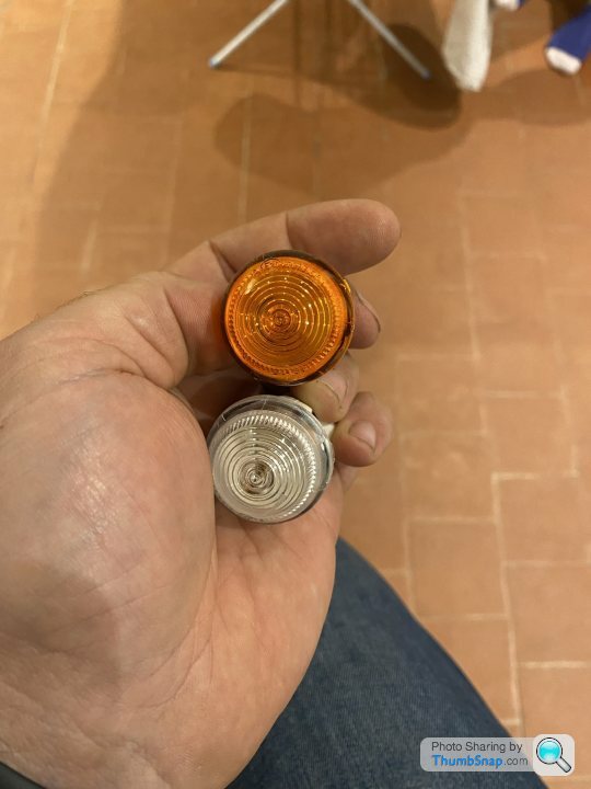
So far pleased with the steering rack I have sourced and some great side and indicator lights.
I have just started accumulating parts for my build, driving to toylander plans mostly but going with a chain drive from a mobility scooter and detailing it where I can.
Hard-drive, love some of the bits you have done with rivets etc. are they real in the MDF.
So far pleased with the steering rack I have sourced and some great side and indicator lights.
Gassing Station | Scale Models | Top of Page | What's New | My Stuff