Toylander from scratch (metal chassis and body)
Discussion


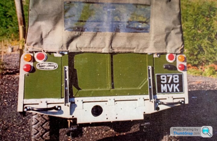
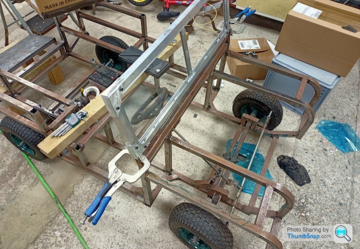
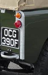
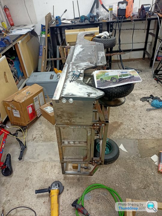
Aiming for this, whilst starting with nothing;
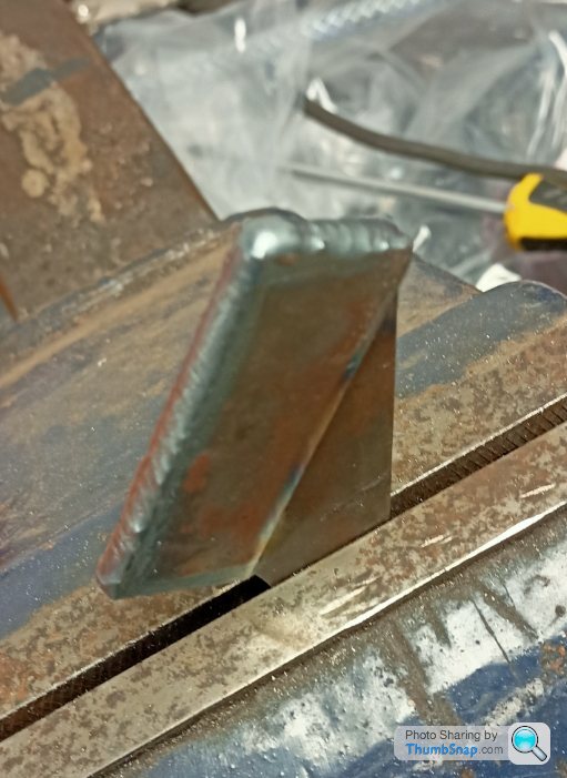
Cut some bad 45s using a 4.5" grinder and assemble.
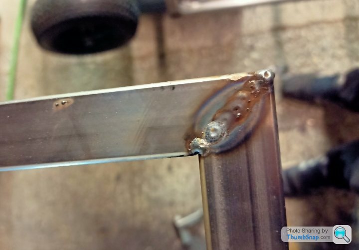
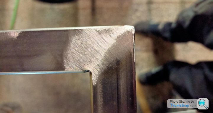
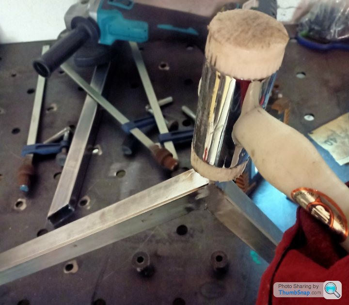
Make untidy weld, tidy;
Due to shrinkage and aforementioned bad 45s adjust angles;
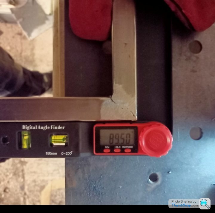
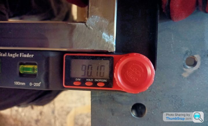
Ensure plastic £7 angle finder for upmost precision.
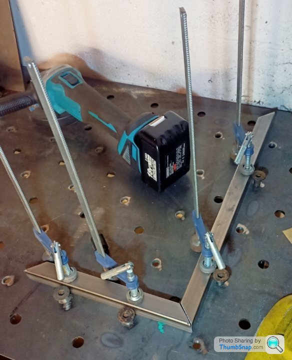
Made a box, surprisingly it still fits;
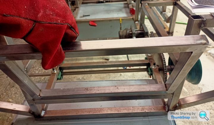
Make centre piece. Any normal person would have stuck some more box section in there, but is slightly too wide compared to the sides, and cutting to the chase I was low on box section.
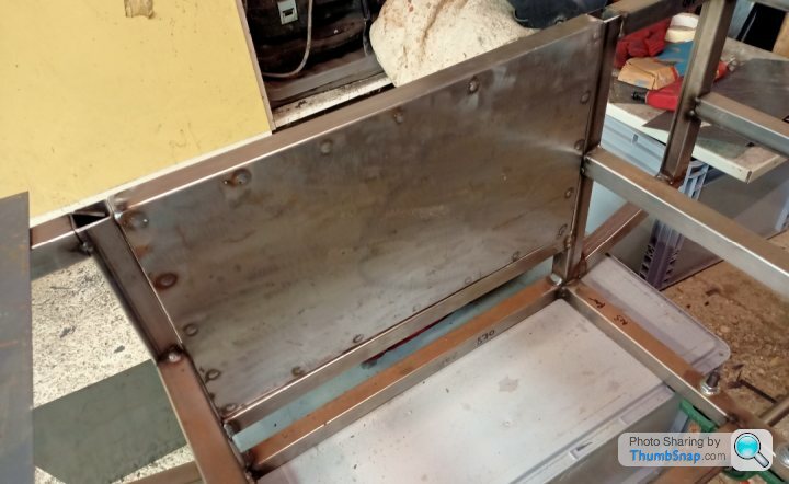
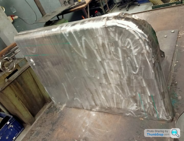
Alas, 45 minutes later, we go from flat sheet to something vaguely like the original;
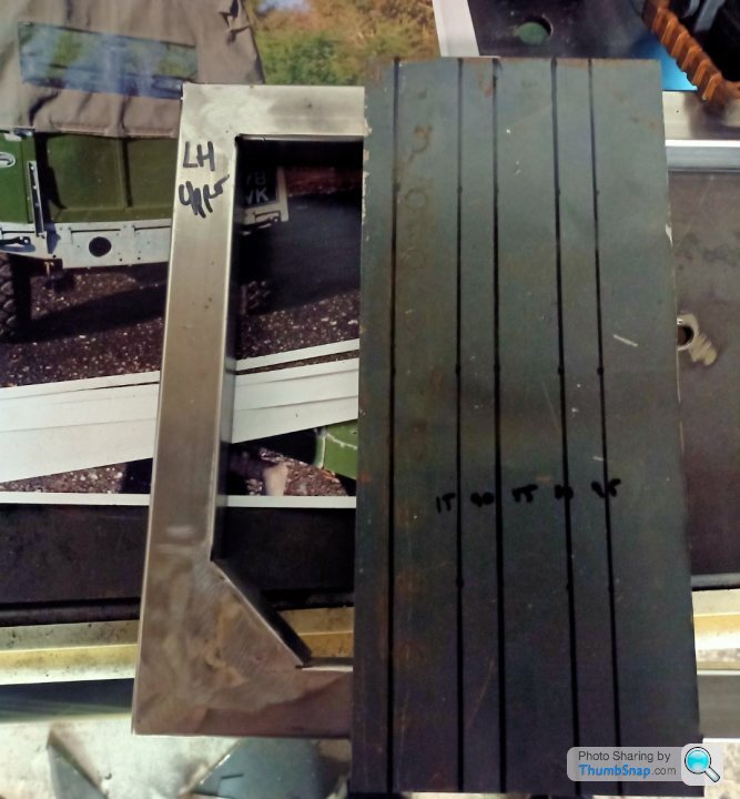
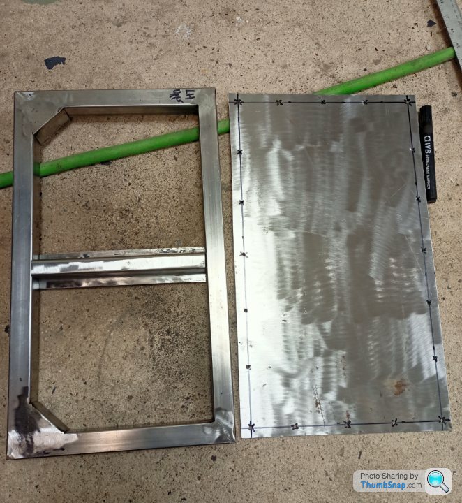
Also you can see triangular pieces in there and the panel has been cut slightly bigger than required and drilled (4mm) ready for some spot welds.
Plug Weld (badly);
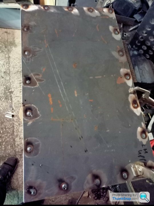
I've done a thing!
That was 5 hours work, although with the right tools and equipment (chop saw, box pan folder, skilled operator) it's probably 2.
Best get to bed really.
Cut some bad 45s using a 4.5" grinder and assemble.
Make untidy weld, tidy;
Due to shrinkage and aforementioned bad 45s adjust angles;
Ensure plastic £7 angle finder for upmost precision.
Made a box, surprisingly it still fits;
Make centre piece. Any normal person would have stuck some more box section in there, but is slightly too wide compared to the sides, and cutting to the chase I was low on box section.
Alas, 45 minutes later, we go from flat sheet to something vaguely like the original;
Also you can see triangular pieces in there and the panel has been cut slightly bigger than required and drilled (4mm) ready for some spot welds.
Plug Weld (badly);
I've done a thing!
That was 5 hours work, although with the right tools and equipment (chop saw, box pan folder, skilled operator) it's probably 2.
Best get to bed really.
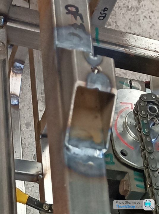
I did a little bit more in the garage last night and a bit at the end of work today. I slotted the motor mount to get a bit more tension in the chain. Lovely.
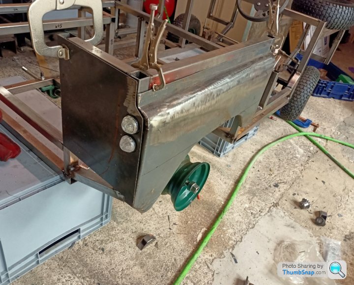
I trimmed the bottom end of the quarter panel where it joins the B pillar so it matches the door and I made a start on the rear light panels.
I had to notch the chassis upright to get the indicator and tail lamps in place. Drill + burr tool gets the job done on 1.2 box section quick.
In the photo none of the panels are clamped properly. As you'll notice the trimming doesn't match the quarter panel well and that's because there will be an aluminium cover plate that covers that whole area. Or at least, that is my excuse!
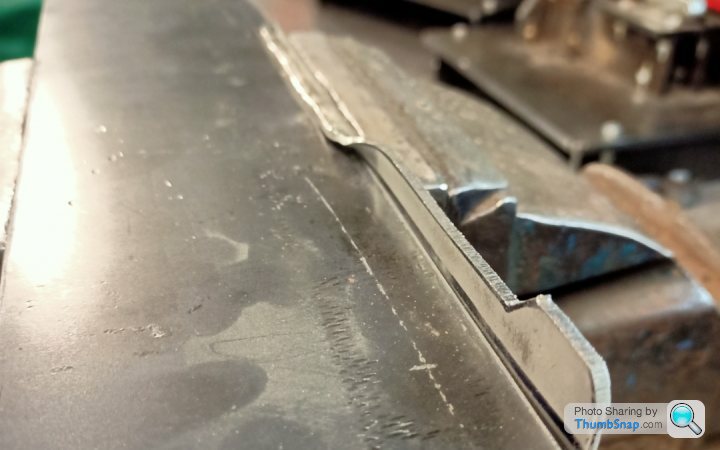
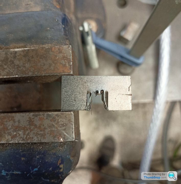
I thought a nice Friday afternoon job once I'd knocked off would be to quickly make up some rear hinges. I'd spotted a bit of 2mm stainless that would do the trick.
What we are trying to make;
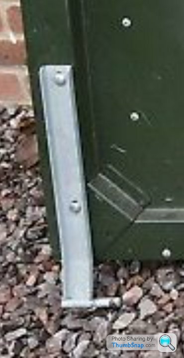
Template, Bandsaw, linish, box pan fold, drill hole, weld 8mm pin in
This should be easy, I'm at work and have some clobber to use...oh no, it's not that easy.
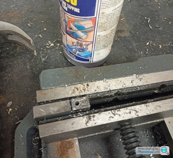
As it's 2mm thick and stainless and the return edge was very small (6mm) it wouldn't have it on the folder. It kept slipping out and not folding across its whole length. With a decent press brake it would be fine but we don't have one. We do have a hammer and a vice though.
Piece of plate to beat the return on, vice to hold it all.

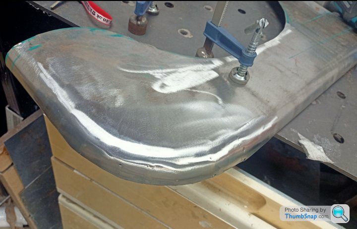
Quarter of the job done:
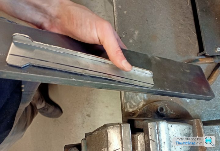
Stainless is pretty forgiving to butchery with a hammer but obviously it marks the face. You have to hit it quite hard as it's 2mm and in a very small area. Hammer marks are the order of the day;
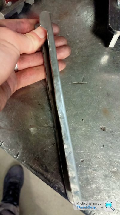
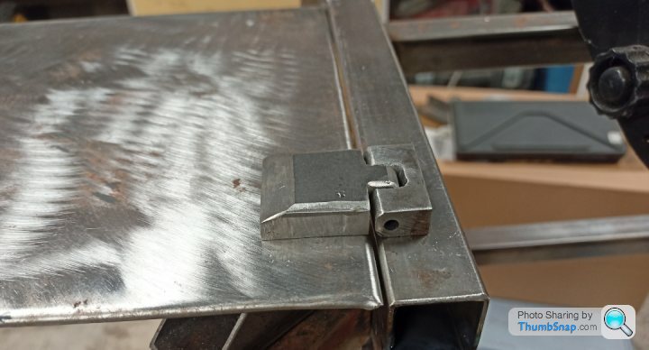
Take one grinder and you can see the 50/50 shot below:
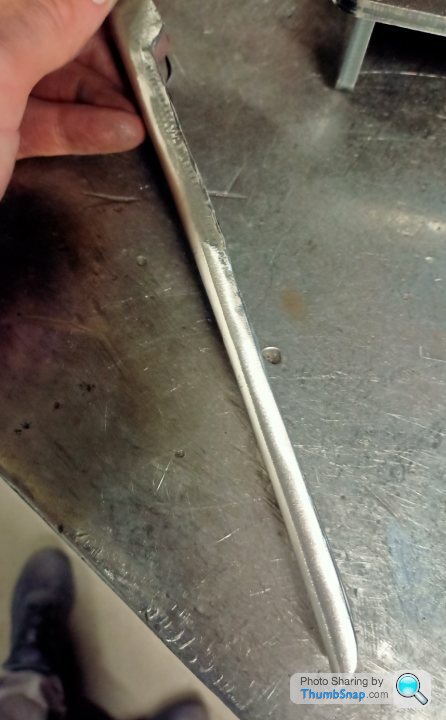
With very basic tools (vice, odd bits of metal, hammer, grinder) you can make quite a lot with metal without much skill. Just be more brutal than you think and it'll be alright! The beauty of 304 stainless on this part is that it won't need to be painted and will look right against the body coloured panels.
Jobs left, drill hole, insert 8mm bar, Tig weld.
I also need to put a little bend in it to get the pivot point away from the chassis so it opens properly. I'll nick a little cut in the return with a grinder, bend it on a v block and Tig weld the cut up. Simple!
I trimmed the bottom end of the quarter panel where it joins the B pillar so it matches the door and I made a start on the rear light panels.
I had to notch the chassis upright to get the indicator and tail lamps in place. Drill + burr tool gets the job done on 1.2 box section quick.
In the photo none of the panels are clamped properly. As you'll notice the trimming doesn't match the quarter panel well and that's because there will be an aluminium cover plate that covers that whole area. Or at least, that is my excuse!
I thought a nice Friday afternoon job once I'd knocked off would be to quickly make up some rear hinges. I'd spotted a bit of 2mm stainless that would do the trick.
What we are trying to make;
Template, Bandsaw, linish, box pan fold, drill hole, weld 8mm pin in
This should be easy, I'm at work and have some clobber to use...oh no, it's not that easy.
As it's 2mm thick and stainless and the return edge was very small (6mm) it wouldn't have it on the folder. It kept slipping out and not folding across its whole length. With a decent press brake it would be fine but we don't have one. We do have a hammer and a vice though.
Piece of plate to beat the return on, vice to hold it all.
Quarter of the job done:
Stainless is pretty forgiving to butchery with a hammer but obviously it marks the face. You have to hit it quite hard as it's 2mm and in a very small area. Hammer marks are the order of the day;
Take one grinder and you can see the 50/50 shot below:
With very basic tools (vice, odd bits of metal, hammer, grinder) you can make quite a lot with metal without much skill. Just be more brutal than you think and it'll be alright! The beauty of 304 stainless on this part is that it won't need to be painted and will look right against the body coloured panels.
Jobs left, drill hole, insert 8mm bar, Tig weld.
I also need to put a little bend in it to get the pivot point away from the chassis so it opens properly. I'll nick a little cut in the return with a grinder, bend it on a v block and Tig weld the cut up. Simple!
After another missed kids birthday, progress and motivation has been lacking!
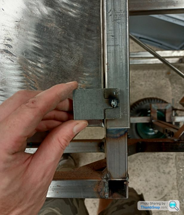
I decided to try and get the rear hatch mounted. I needed to finish off the U shaped brackets, make some hinge mounts and other stuff. Whim and a prayer job really.
Rear hatch brackets drilled for 8mm bar and Tek screws to give it a more authentic look. Obviously the Tek screws I had needed cutting down about 40mm. Why make like easy.
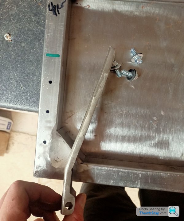
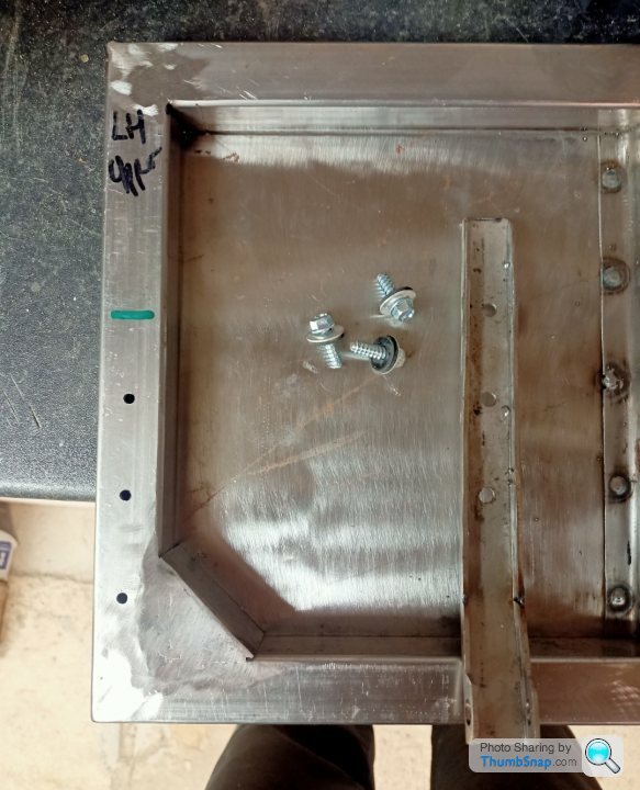
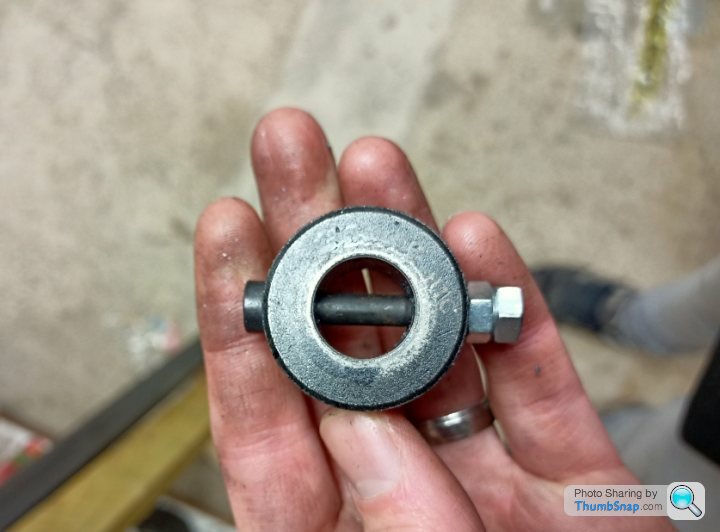
I needed a support piece for the chassis, then hand cut the chassis bracket out of 3mm MS. I welded two 8mm nuts together and drilled them out to 8.5mm, which is probably the most cheapskate way you will see of making a boss for the tailgate to hinge on. Cest la vie!
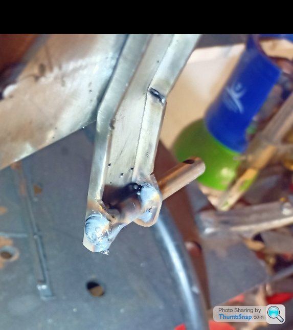
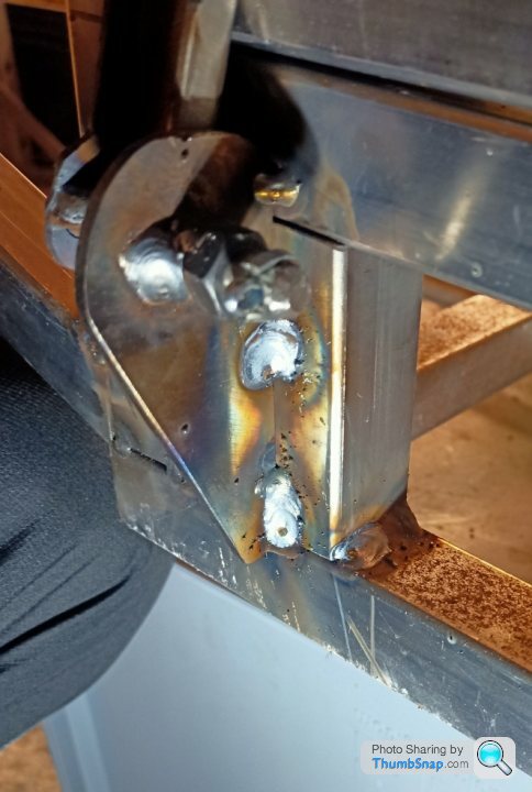
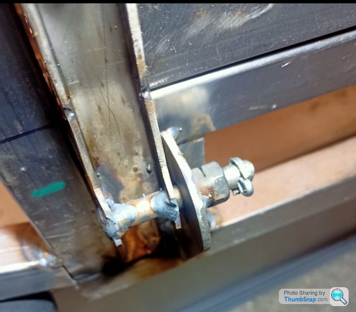
I think it's fairly obvious how it works and much like the original. The 8mm bar is welded to the tailgate hinge. It passes through my rough 8.5mm boss and is secured from falling out with the split pin. To fit or remove the tailgate, you open it up, remove split pins and slide out. Nice. I need to make some catches for the top but then that is done. What amazing progress.
Through more luck than judgement it will open all the way so that it's vertically down without hitting the floor. That should allow the kids to get in a lot easier when they are 17.
I decided to try and get the rear hatch mounted. I needed to finish off the U shaped brackets, make some hinge mounts and other stuff. Whim and a prayer job really.
Rear hatch brackets drilled for 8mm bar and Tek screws to give it a more authentic look. Obviously the Tek screws I had needed cutting down about 40mm. Why make like easy.
I needed a support piece for the chassis, then hand cut the chassis bracket out of 3mm MS. I welded two 8mm nuts together and drilled them out to 8.5mm, which is probably the most cheapskate way you will see of making a boss for the tailgate to hinge on. Cest la vie!
I think it's fairly obvious how it works and much like the original. The 8mm bar is welded to the tailgate hinge. It passes through my rough 8.5mm boss and is secured from falling out with the split pin. To fit or remove the tailgate, you open it up, remove split pins and slide out. Nice. I need to make some catches for the top but then that is done. What amazing progress.
Through more luck than judgement it will open all the way so that it's vertically down without hitting the floor. That should allow the kids to get in a lot easier when they are 17.
So after a couple of months we are all expecting big updates right...
...Hmm, Summer, hot, nice evenings, beer. What other excuses do I need to admit zero progress. Oh yeah, works been mental, so enthusiasm has been low. Still, they are a long way off being 17. Obviously now the evenings are drawing in, its cold and wet it'll be much more likely I'll spend some time in the garage.
OK, that is a lie, I did buy some aluminium box section, U channel for the windscreen and some 2x1 for the front bumper bar metalwork.
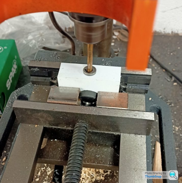
I also bought a vice for my (VERY hobby) pillar drill in a vein attempt that I can cross drill my axle somewhat centrally. The vice is nearly as big as the pillar drill base.
I might even have done something with a throttle pedal if my memory serves me right. Its full pat butcher spec.
Anyhow, now you guys have bumped the thread, I'm feeling guilty, and envious of your ones so I better do something in the next couple of weeks. Cobain, pictures, pictures, pictures when the panels turn up.
...Hmm, Summer, hot, nice evenings, beer. What other excuses do I need to admit zero progress. Oh yeah, works been mental, so enthusiasm has been low. Still, they are a long way off being 17.
Obviously now the evenings are drawing in, its cold and wet it'll be much more likely I'll spend some time in the garage. OK, that is a lie, I did buy some aluminium box section, U channel for the windscreen and some 2x1 for the front bumper bar metalwork.
I also bought a vice for my (VERY hobby) pillar drill in a vein attempt that I can cross drill my axle somewhat centrally. The vice is nearly as big as the pillar drill base.
I might even have done something with a throttle pedal if my memory serves me right. Its full pat butcher spec.
Anyhow, now you guys have bumped the thread, I'm feeling guilty, and envious of your ones so I better do something in the next couple of weeks. Cobain, pictures, pictures, pictures when the panels turn up.
That paint looks pretty good to me. I'll order some of that from them at some point.
I am still torn between whether to paint it the traditional "blue" or "green" that they are normally seen in. Hard Drive what was the official colour as that site seems to have shade after shade that all look like it to my (very) untrained eye! Series 2 vintage.
One of the issues that I have been putting off for eternity is cross drilling the axle. I have various things that I need to attach to my axle, including the sprocket, jaw couplings and a brake disc. Whilst they could be welded on and that would be super easy, removing them for servicing/repairing/replacing becomes somewhat of a challenge.
The difficultly of cross drilling an axle is trying to get it square. I've delved into youtube and seen people pushing down on drills with a ruler precariously balanced onto the axle trying to find the level. This probably works quite well if you are doing it on a mill and you can move the bed in X and Y. I haven't got one of those.
Option 2 is give it to my machinist at work and let him fumble about with it, but then I need to accurately mark where I want everything, and go back numerous times to him when I put it in the wrong place originally. Lets not do that. Lets waste some time designing something badly to 3D print.
20 minutes later, this is what we have;
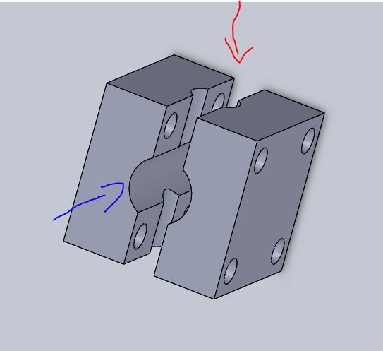
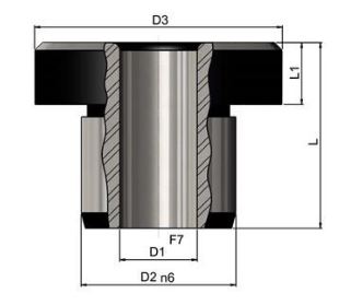
I'll get a drill bush to go in where the Red arrow is:
The axle will be clamped in the blue arrow section.
You get the idea, I need to firm up the axle size as I can't remember it, print one off, order a drill bush and see how much I cock it up by!
In theory I can modify the design quickly and print one off for the different sizes of parts that I am attaching. EG the JAW coupling will be bigger in the blue arrow area.
The good news is that this post is live and I just finished the drawing a minute ago. Therefore if you never see anything about this again, you'll know it didn't work well and I gave it to the machinist after all. I'm sort of predicting a certain amount of fannying about getting the drill bush and the axle to stay tight in there at the same time. Fortunately the drill bush isn't really taking much load, so if its a bit loose it shouldn't be the end of the world...Worst case is I can make the top part solid and just have the slot in the lower part. In fact I might try that first.
I am still torn between whether to paint it the traditional "blue" or "green" that they are normally seen in. Hard Drive what was the official colour as that site seems to have shade after shade that all look like it to my (very) untrained eye! Series 2 vintage.
One of the issues that I have been putting off for eternity is cross drilling the axle. I have various things that I need to attach to my axle, including the sprocket, jaw couplings and a brake disc. Whilst they could be welded on and that would be super easy, removing them for servicing/repairing/replacing becomes somewhat of a challenge.
The difficultly of cross drilling an axle is trying to get it square. I've delved into youtube and seen people pushing down on drills with a ruler precariously balanced onto the axle trying to find the level. This probably works quite well if you are doing it on a mill and you can move the bed in X and Y. I haven't got one of those.
Option 2 is give it to my machinist at work and let him fumble about with it, but then I need to accurately mark where I want everything, and go back numerous times to him when I put it in the wrong place originally. Lets not do that. Lets waste some time designing something badly to 3D print.
20 minutes later, this is what we have;
I'll get a drill bush to go in where the Red arrow is:
The axle will be clamped in the blue arrow section.
You get the idea, I need to firm up the axle size as I can't remember it, print one off, order a drill bush and see how much I cock it up by!
In theory I can modify the design quickly and print one off for the different sizes of parts that I am attaching. EG the JAW coupling will be bigger in the blue arrow area.
The good news is that this post is live and I just finished the drawing a minute ago. Therefore if you never see anything about this again, you'll know it didn't work well and I gave it to the machinist after all.
I'm sort of predicting a certain amount of fannying about getting the drill bush and the axle to stay tight in there at the same time. Fortunately the drill bush isn't really taking much load, so if its a bit loose it shouldn't be the end of the world...Worst case is I can make the top part solid and just have the slot in the lower part. In fact I might try that first. I should have mentioned the reason to cross drill the axle is to use something like a roll pin, or be ghetto and use a bolt and nut, to secure the various items onto the axle so that the motor turns the axle via the pinned sprocket, the wheels are also pinned to the axle and the brake slows the axle and therefore wheels. Simple...until I drill something in the wrong place.
So 6 weeks on, a huge update incoming...
Or maybe just a little one. I updated my cross drill model a bit to make it easier to use and take up less room axially.
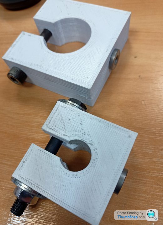
Couple of different sizes for the different outside diameter things I need pinning onto the axle.
So, did it work?
In the words of Jezza, "I did a thing"
Baby steps, Baby steps...
Or maybe just a little one. I updated my cross drill model a bit to make it easier to use and take up less room axially.
Couple of different sizes for the different outside diameter things I need pinning onto the axle.
So, did it work?
In the words of Jezza, "I did a thing"
Baby steps, Baby steps...
After a mere 8 months, progress has been strong. Just not on the toylander. I'm about to leave my current automotive job after 14 years to do something a bit different. Perhaps one of the side effects will be more motivation to do some of my car/toylander projects... We'll see.
Toylander, yes it still is a thing, looking in a similar state to before but there have been a few things done.
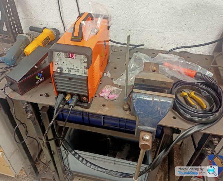
- I bought a new TIG welder which is a Chinese special for £340 delivered. It has all the important functions that you typically want. High frequency start, pulse setup, optional pedal(yes I got one), AC and DC so I can try aluminium at some point. Combined with a bottle of pure argon for a £100 (£60 bottle deposit) and we are ready to melt some metal.
Obviously it is easy to buy some tools and equipment rather than actually do the job...
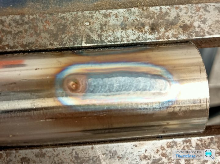
The first photo is just setting up the machine on some stainless tube, it needed a bit more gas, slightly less heat to avoid the greying out. Learning right!
Second is mild steel fusing to space out the A pillar windscreen mount as I made the windscreen a couple of mm too wide
The bit that takes the time to learn and I haven't done it yet is to start feeding filler rod in. That's when the skill comes, anyone could fuse some metal together within an hour of using the machine.
So the toylander, hmm...
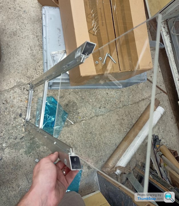
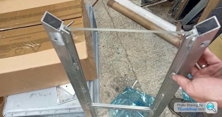
Well these jobs are mostly done now;
1) windscreen is 90% made
2) converted to single wheel drive (hard drive was right!) with the aide of a bearing on the NSR
3) axle cross drilled and sprocket is on
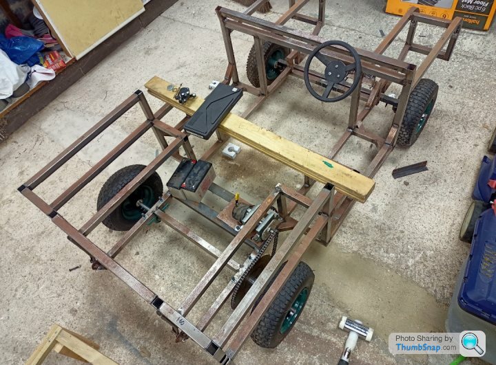
Well that looks similar to before... And no windscreen pic. Bad times.
Immediate to do list is;
Get friendly machinist at current workplace to knob up brake disc axle mount
Remember to take my material from current work, to home, so I don't lose it for good.
Try and get it ready for this Christmas, or at least a state where the boys can drive it around even if it is cosmetically challenged.
Toylander, yes it still is a thing, looking in a similar state to before but there have been a few things done.
- I bought a new TIG welder which is a Chinese special for £340 delivered. It has all the important functions that you typically want. High frequency start, pulse setup, optional pedal(yes I got one), AC and DC so I can try aluminium at some point. Combined with a bottle of pure argon for a £100 (£60 bottle deposit) and we are ready to melt some metal.
Obviously it is easy to buy some tools and equipment rather than actually do the job...
The first photo is just setting up the machine on some stainless tube, it needed a bit more gas, slightly less heat to avoid the greying out. Learning right!
Second is mild steel fusing to space out the A pillar windscreen mount as I made the windscreen a couple of mm too wide
The bit that takes the time to learn and I haven't done it yet is to start feeding filler rod in. That's when the skill comes, anyone could fuse some metal together within an hour of using the machine.
So the toylander, hmm...
Well these jobs are mostly done now;
1) windscreen is 90% made
2) converted to single wheel drive (hard drive was right!) with the aide of a bearing on the NSR
3) axle cross drilled and sprocket is on
Well that looks similar to before... And no windscreen pic. Bad times.
Immediate to do list is;
Get friendly machinist at current workplace to knob up brake disc axle mount
Remember to take my material from current work, to home, so I don't lose it for good.
Try and get it ready for this Christmas, or at least a state where the boys can drive it around even if it is cosmetically challenged.
Jon_Bmw said:
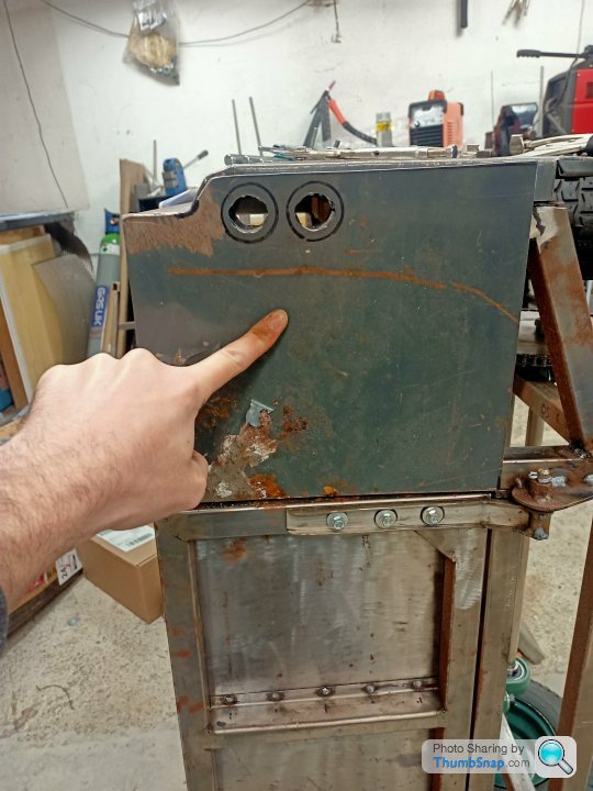
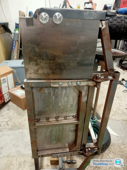
Remember that gash panel, well this is it after a bit of sanding with a flappy pad... I was about to bin it when I just thought I'd have a quick sanding session.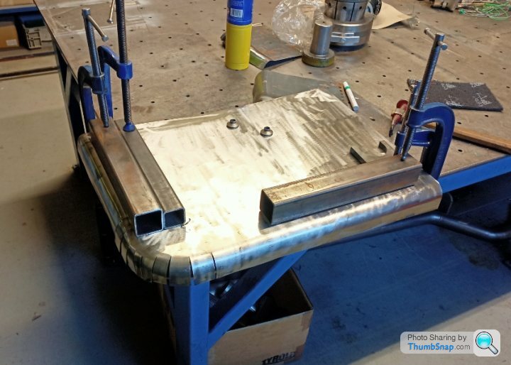

A few holes to fill with the welder and I'm sure it's very thin in places. Lightweight is all the rage these days...
In the realms of getting it finished this decade I'll probably make do with it and perhaps put a skim of filler on it to hide the last couple of high/low points.
I can always replace it in the future. Yeah right!
Thanks Eccles, I'm going for the ropey look I think. Kids can smash it about a bit, albeit hopefully not into my real car, then it will be ropey with patina. Nice.
Had some time today as I'm between jobs, weather was perfect for bashing around in the garage and welding metal...
First job, remake thinner B pillar. I was lazy and just used a piece of box section and radius'd (new word) off the top to loosely match the door and wing. Weld it to chassis.
Thought I better try and attach a panel at some point. I contemplated the front wing for about 30 seconds and thought better of it. It needs work. So, rear quarter then.
I need to mount the panels 1 inch off the chassis so that the 1" radius meets up nicely with the chassis at the top. I had some 45 strengtheners kicking around which were repurposed. Drill a hole in the top, weld a nut underneath and you get something like this;
Make three of those and offset them around the panel slightly. Work out where approximately they go, drill the panel, bolt the strengtheners to the panel, place the panel on the chassis. Use some c clamps to hold the strengtheners to the chassis, unbolt the panel. Weld the strengtheners.
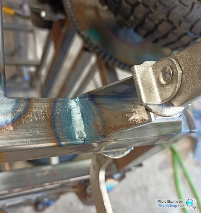
Ooooo (bad) TIG weld from my new machine. More learning required. Do three of them, take photo of 'best' weld and move on.
Drill panel out more as nothing lines up.
Fit panel, bolts to be replaced with button heads or something like that in the future. I thought rivets, but with lots of poor planning it is very likely this is going to come on and off a LOT of times. This is the not to scale, not real life, ropey land rover after all.
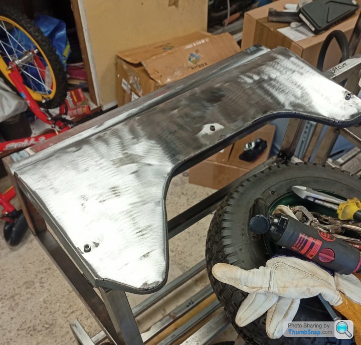
Wheel is useful for storing tools. I think I can get more on than that.
Right doors, it would be nice if they opened wouldn't it. Need some hinges to go on our new B pillar and door. Errr, better find some thicker metal then.
Start with shreddies box and a pencil.
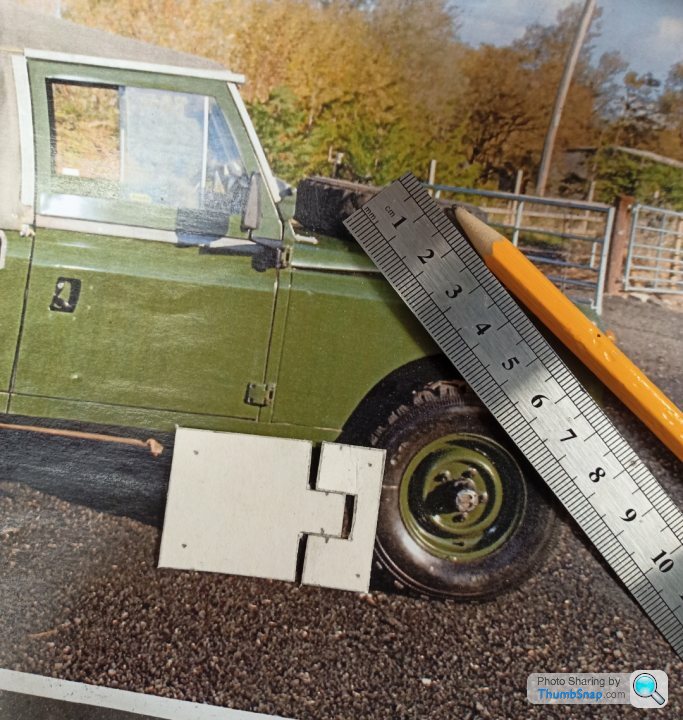
Find 10mm metal in garage, make lots and lots of grinding dust with disc cutter;
Make the other part. Tack it together for drilling stage;
Hole slightly on the angle, check.
Titivate it a bit;
It might look a bit like a real one, I'm unsure really as I had an A4 picture of the entire side of a car to base that hinge on. If history is good judge of future performance, it's probably not.
So that hinge took 2 hours of messing about. I'll get a brother from another mother to cad and laser the other 3 and then I can just do the drilling and titivating stage without filling the entire garage in a layer of metal dust. Maybe even save some time. Let's get 6 so that we have a few drill practises. And pick the best of the bunch.
Bonus sneak peak, a few panels paid on;
I told you I could get more tools on that wheel.
Had some time today as I'm between jobs, weather was perfect for bashing around in the garage and welding metal...
First job, remake thinner B pillar. I was lazy and just used a piece of box section and radius'd (new word) off the top to loosely match the door and wing. Weld it to chassis.
Thought I better try and attach a panel at some point. I contemplated the front wing for about 30 seconds and thought better of it. It needs work. So, rear quarter then.
I need to mount the panels 1 inch off the chassis so that the 1" radius meets up nicely with the chassis at the top. I had some 45 strengtheners kicking around which were repurposed. Drill a hole in the top, weld a nut underneath and you get something like this;
Make three of those and offset them around the panel slightly. Work out where approximately they go, drill the panel, bolt the strengtheners to the panel, place the panel on the chassis. Use some c clamps to hold the strengtheners to the chassis, unbolt the panel. Weld the strengtheners.
Ooooo (bad) TIG weld from my new machine. More learning required. Do three of them, take photo of 'best' weld and move on.
Drill panel out more as nothing lines up.
Fit panel, bolts to be replaced with button heads or something like that in the future. I thought rivets, but with lots of poor planning it is very likely this is going to come on and off a LOT of times. This is the not to scale, not real life, ropey land rover after all.
Wheel is useful for storing tools. I think I can get more on than that.
Right doors, it would be nice if they opened wouldn't it. Need some hinges to go on our new B pillar and door. Errr, better find some thicker metal then.
Start with shreddies box and a pencil.
Find 10mm metal in garage, make lots and lots of grinding dust with disc cutter;
Make the other part. Tack it together for drilling stage;
Hole slightly on the angle, check.
Titivate it a bit;
It might look a bit like a real one, I'm unsure really as I had an A4 picture of the entire side of a car to base that hinge on. If history is good judge of future performance, it's probably not.
So that hinge took 2 hours of messing about. I'll get a brother from another mother to cad and laser the other 3 and then I can just do the drilling and titivating stage without filling the entire garage in a layer of metal dust. Maybe even save some time. Let's get 6 so that we have a few drill practises. And pick the best of the bunch.
Bonus sneak peak, a few panels paid on;
I told you I could get more tools on that wheel.
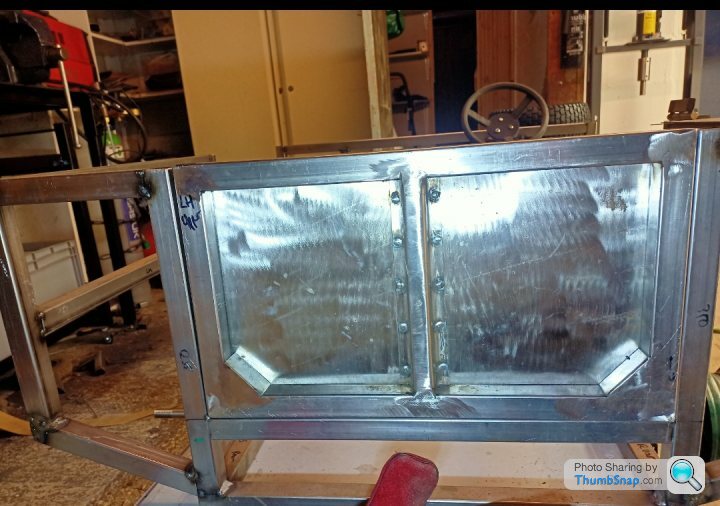
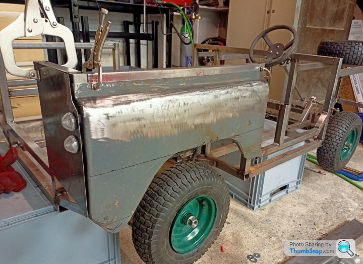
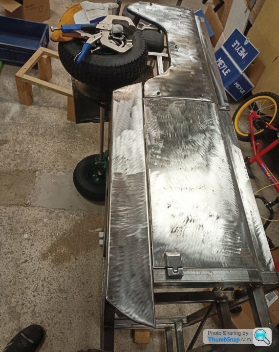
I fitted up the lower sill panel and bolted that on, the same way as the others;
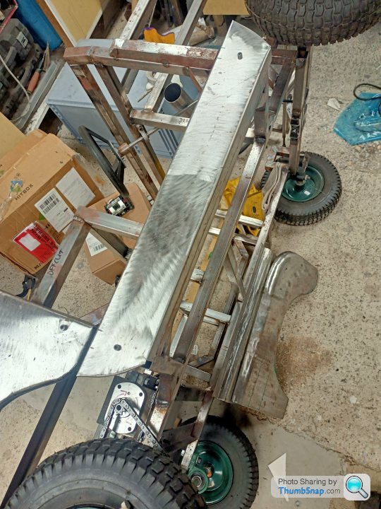
I will replace the bolts at some point, most likely with stainless button heads. I think they will be on and off a fair few times yet though.
Then had a quick go at one of the rear panels;
Make it shiny with paint removal tool;
The joint will get hidden with an Aluminium cover panel at some point:
A look down the side, I will paint the lights Red and Orange at some point:
Yep, that looks like some badly fitted Land Rover panels alright.
Onto other news, I started a new job, which is not very much like my old one, and a distinctly zero time/opportunity to get bashing metal anymore... It would be difficult in a shirt and tie I suppose. All very boring.
One of the other downsides, was giving up my access to a very expensive Solidworks licence, now despite me never really using it much, I now miss it. So I downloaded Fusion 360, which a lot of the content is free for hobbyists as long as its not for commercial gain. Considering as this is costing a fortune, mainly in time, I wonder if Fusion will pay me...
I had already tasked my friend to knock up the hinges for the laser cutters but I thought I would give it a crack on Fusion. It actually appears more use friendly for novices than Solidworks. So here they are;

All of the radius will be done by hand with a grinder as I am not paying for someone to machine them albeit I have requested my machinist friend to spot face the 6mm holes so the bolts sit against a flat, recessed face.
Like anything new, its almost therapeutic. I suspect it is could be very tedious if its your day job and you are designing simple things like this.
So a little progress, but not too much to get excited about. Story of my life really.
I will replace the bolts at some point, most likely with stainless button heads. I think they will be on and off a fair few times yet though.
Then had a quick go at one of the rear panels;
Make it shiny with paint removal tool;
The joint will get hidden with an Aluminium cover panel at some point:
A look down the side, I will paint the lights Red and Orange at some point:
Yep, that looks like some badly fitted Land Rover panels alright.
Onto other news, I started a new job, which is not very much like my old one, and a distinctly zero time/opportunity to get bashing metal anymore... It would be difficult in a shirt and tie I suppose. All very boring.
One of the other downsides, was giving up my access to a very expensive Solidworks licence, now despite me never really using it much, I now miss it. So I downloaded Fusion 360, which a lot of the content is free for hobbyists as long as its not for commercial gain. Considering as this is costing a fortune, mainly in time, I wonder if Fusion will pay me...
I had already tasked my friend to knock up the hinges for the laser cutters but I thought I would give it a crack on Fusion. It actually appears more use friendly for novices than Solidworks. So here they are;
All of the radius will be done by hand with a grinder as I am not paying for someone to machine them albeit I have requested my machinist friend to spot face the 6mm holes so the bolts sit against a flat, recessed face.
Like anything new, its almost therapeutic. I suspect it is could be very tedious if its your day job and you are designing simple things like this.
So a little progress, but not too much to get excited about. Story of my life really.
Edited by Jon_Bmw on Sunday 5th November 22:18
Gassing Station | Scale Models | Top of Page | What's New | My Stuff