Airfix 1:72 Vulcan B.2
Discussion


So on to the intakes. Again. After a successful re-flatting and priming, once again the Vallejo Off-White pooled and ran. This was despite using thicker than normal paint in the airbrush, and a low pressure. The paint also seems to blister in random places for some reason. I can’t remember this happening before with Tamiya primer and Vallejo paint. Obviously there are different chemicals in different colours, but still a bit odd.


Not quite sure what I keep doing wrong here, but, I can’t progress until they’re done. Every error here takes days for the paint to harden before it’s worth trying to correct it.
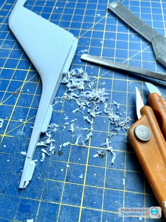
The wing sink mark filling did’t go well; they’re deep enough to see (and can’t be unseen), but too shallow to fill effectively. Exactly like the sink marks in the Airfix Swordfish wing. Plus, the more I look at it, more sink marks become apparent. Like the Swordfish, this thing is slowly sapping the enthusiasm to bother.
Anyway, I’m not starting another until it’s done this time, so on to the Blue Steel missile. Flatted the seams and filled any gaps with Milliput:

It’s perfect for jobs like that, because you can remove the excess and blend to a perfect finish without trying to sand in impossible to get to places:

Plan with this is to use Tamiya white primer as the final finish, and use a mechanical pencil for the panel lines. I want it to look pristine, but with something to break up the expanse of white.
Not quite sure what I keep doing wrong here, but, I can’t progress until they’re done. Every error here takes days for the paint to harden before it’s worth trying to correct it.
The wing sink mark filling did’t go well; they’re deep enough to see (and can’t be unseen), but too shallow to fill effectively. Exactly like the sink marks in the Airfix Swordfish wing. Plus, the more I look at it, more sink marks become apparent. Like the Swordfish, this thing is slowly sapping the enthusiasm to bother.
Anyway, I’m not starting another until it’s done this time, so on to the Blue Steel missile. Flatted the seams and filled any gaps with Milliput:
It’s perfect for jobs like that, because you can remove the excess and blend to a perfect finish without trying to sand in impossible to get to places:
Plan with this is to use Tamiya white primer as the final finish, and use a mechanical pencil for the panel lines. I want it to look pristine, but with something to break up the expanse of white.
IJWS15 said:
It looks as if the front winglets are movable in flight so shouldn't there be a slight gap between them and the missile body?
Yes, the canards move, but they were a very close fit. It's very difficult to get a very small, but consistent gap of the right scale - too big a gap and it looks all wrong. I opted to fill it, and then I'll go around the joint with a dark wash to suggest a gap. I found a picture somewhere of the real thing, but it's on my other laptop.r159 said:
Bugger on the intakes...out of interest when I use Milliput its as sticky as a b d, what do you do to stop it going all over everything when mixing it?
I mix it using a bit of spit, and accept it goes over your fingers and anything else it happens to contact. Once it's mixed, I wash it all off my hands and don't touch it again. I use some plastic spreaders or a cocktail stick, and wipe any excess off with a damp cloth.d, what do you do to stop it going all over everything when mixing it?Tried for the second time to get the radome scribing right. When viewed from the side, the rear vertical panel line needs to appear parallel to the bulkhead line further back. After eyeballing it and getting it wrong, I opted to set it with a height gauge. First checking the bulkhead line is parallel with the bench all around:

Then dotting some black paint on the scriber tip, and touching it on to the compound curved surface of the nose:

I’ll join the dots by best-fitting a thin strip of Dymo tape, and scribing the line to that.
Then dotting some black paint on the scriber tip, and touching it on to the compound curved surface of the nose:
I’ll join the dots by best-fitting a thin strip of Dymo tape, and scribing the line to that.
davettf2 said:
Excellent alternative use for slip gauges!
Fantastic dedication, and following with interest, keep up the great work.
Thanks! Slip gauges are great for many things totally inappropriate for maintaining their accuracy. Has the added benefit of causing outrage on the Model Engineer forum - on a par with my occasional use of digital calipers as scribers and clamps.Fantastic dedication, and following with interest, keep up the great work.
Anyway, the scribed radome line seems to be in the right place now:


Intake masking. I wanted to do this before assembly, because it looked quite tricky.
Airfix thoughtfully provided paper cut-out templates as a guide, but how on Earth you’re supposed to use them is anyone’s guess. The instructions seem to show them being used to draw around before assembly of the intake halves…but the white would have to have been applied first for this to work, in which case how are you supposed to deal with the joint lines without ruining the paint? Anyway, I put them in place at this stage (when access is pretty much impossible). They are marked for top and bottom:
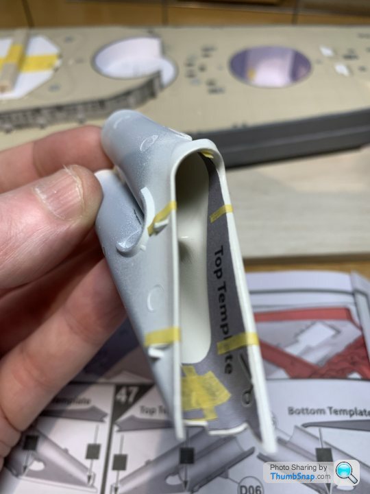

Oh dear:

Somewhat confused, I then removed them, turned them print side down, but they’re still wrong - just wrong on the opposite side. The only way I could get them kind of right was to swap them top to bottom. Seems like they been printed on the wrong parts.
All in all a bit of a pointless exercise as far as I can see. Would have been better to make the intake mouths separate parts along the demarcation line for what it’s worth.
So currently doing it all by eye, which inevitably ends in re-work at a very tricky stage.
Airfix thoughtfully provided paper cut-out templates as a guide, but how on Earth you’re supposed to use them is anyone’s guess. The instructions seem to show them being used to draw around before assembly of the intake halves…but the white would have to have been applied first for this to work, in which case how are you supposed to deal with the joint lines without ruining the paint? Anyway, I put them in place at this stage (when access is pretty much impossible). They are marked for top and bottom:
Oh dear:
Somewhat confused, I then removed them, turned them print side down, but they’re still wrong - just wrong on the opposite side. The only way I could get them kind of right was to swap them top to bottom. Seems like they been printed on the wrong parts.
All in all a bit of a pointless exercise as far as I can see. Would have been better to make the intake mouths separate parts along the demarcation line for what it’s worth.
So currently doing it all by eye, which inevitably ends in re-work at a very tricky stage.
Intake masking pretty much done:


I’ll cut out some oval paper discs and Maskol them around their edges to seal the inner ducts.
Then prepared the compressor and turbine faces:
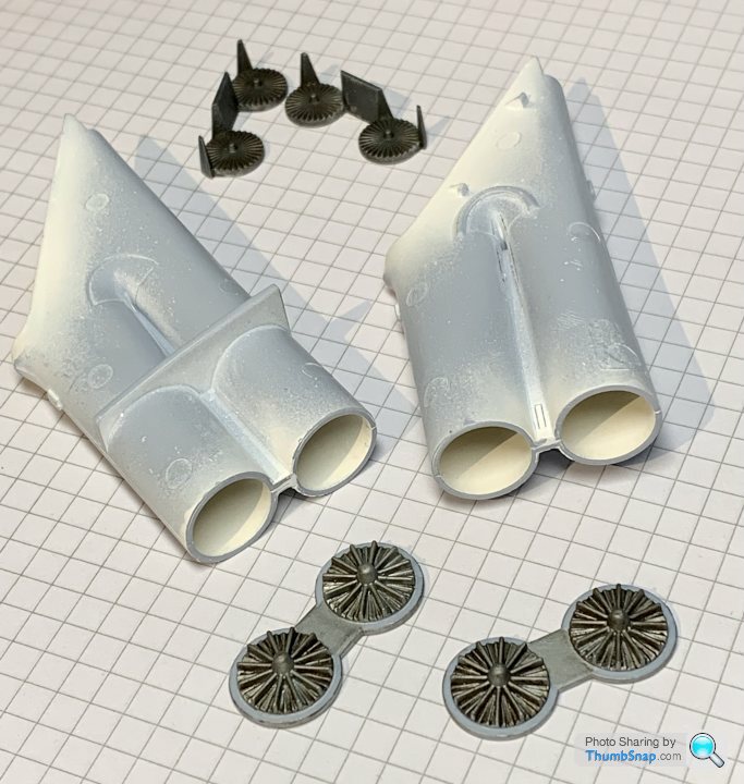
Seems like a long time since I applied any glue to this model, but attached the inserts:

I’d already Matt varnished the back of the ducts (adjacent to the faces), because I assumed once capped, they’d form a big dead spot for the airbrush. I left the forward openings gloss so that the masking tape would attach better.
Then the turbines:

After cleaning up all mating faces, I temporarily fixed the spar structure to the lower wing halves:
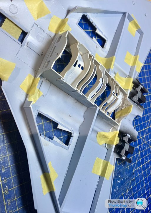
And glued the central joints:

I want to eliminate the joint lines on the front wheel well and bomb bay edges, paint and weather, before fitting the already finished well and bay.
Finally, had to clamp the front joint with locking forceps. It was so badly warped that tape or clothes pegs wouldn't hold it. It’ll be pure luck if that join lines up with the nose properly; I’m expecting a load of corrective work to be needed around there:

I’ll cut out some oval paper discs and Maskol them around their edges to seal the inner ducts.
Then prepared the compressor and turbine faces:
Seems like a long time since I applied any glue to this model, but attached the inserts:
I’d already Matt varnished the back of the ducts (adjacent to the faces), because I assumed once capped, they’d form a big dead spot for the airbrush. I left the forward openings gloss so that the masking tape would attach better.
Then the turbines:
After cleaning up all mating faces, I temporarily fixed the spar structure to the lower wing halves:
And glued the central joints:
I want to eliminate the joint lines on the front wheel well and bomb bay edges, paint and weather, before fitting the already finished well and bay.
Finally, had to clamp the front joint with locking forceps. It was so badly warped that tape or clothes pegs wouldn't hold it. It’ll be pure luck if that join lines up with the nose properly; I’m expecting a load of corrective work to be needed around there:
Noticed that the distinctive crew hatch actuators are missing. Strange, since the other similar items for the gear doors are included, but barely visible.

Since they are a conspicuous feature that should have been included in the kit, I made some up out of brass tube:

Locating dimples were also made in the hatch and the cockpit floor:

I’d have made the brackets for each end for any other build, but these will do for this one:

After wrestling the warped forward fuselage together, I noticed a large gap at the back of the front wheel well:

So currently making a plasticard shim to fill it. At times, the work needed on this thing is like building an old school short-run kit.
Since they are a conspicuous feature that should have been included in the kit, I made some up out of brass tube:
Locating dimples were also made in the hatch and the cockpit floor:
I’d have made the brackets for each end for any other build, but these will do for this one:
After wrestling the warped forward fuselage together, I noticed a large gap at the back of the front wheel well:
So currently making a plasticard shim to fill it. At times, the work needed on this thing is like building an old school short-run kit.
Bit of progress: fitted the spar structure and wheel wells, I reinforced all the joins with Araldite - if the main gear bays come loose when the weight of the model is on them, there’s no coming back from that. I might put blobs of Milliput on their roofs as well, to brace them against the upper wings:

I also fitted the intake ducts, again reinforcing the joints with Araldite:

Despite the fits-where-it-touches situation with some of the other main parts, these locate accurately, with pretty much a perfect fit all around the complex curves of the opening.
I also fitted the intake ducts, again reinforcing the joints with Araldite:
Despite the fits-where-it-touches situation with some of the other main parts, these locate accurately, with pretty much a perfect fit all around the complex curves of the opening.
Joined the upper halves today. Needed clamps and weights to get things to a point where they can at least be filled and flatted smooth later on:

The upper spine is warped along the edges such that the fin sockets are narrow at the top. This is to the extent that the keys in the base of the fin won’t fit in them. If, after narrowing the keys, it results in a step around the base of the fin, it’ll be in the bin. It’s just not worth the effort.
The upper spine is warped along the edges such that the fin sockets are narrow at the top. This is to the extent that the keys in the base of the fin won’t fit in them. If, after narrowing the keys, it results in a step around the base of the fin, it’ll be in the bin. It’s just not worth the effort.
magpie215 said:
dr_gn said:
it’ll be in the bin. It’s just not worth the effort.
I've been put off doing this Vulcan now....think it's way over my skillset.If you do bin it the nose section is ripe for a preserved aircraft museum exhibit diorama.
Had some time earlier to thin the fin tabs, and enlarge the closed-up sockets:
Crucially, any visible step between the fuselage pad and the fin footprint is very minor:

Yes, there’s a gap, but some Milliput should fix that.
Now onto the bomb bay roof:

I kind of understand the design of overlapping geometry here, and it might have looked good on CAD, but mine just doesn’t fit right, and will make fettling of these intricate and visible details very difficult. Not sure why a simple butt-joint wouldn’t have sufficed in these areas, as it does for thousands of other kit fuselage joints. I’ll probably find out why they didn’t do that, because mine is now effectively a butt-joint having given up and sliced the tabs off and glued them into their recesses.
Crucially, any visible step between the fuselage pad and the fin footprint is very minor:
Yes, there’s a gap, but some Milliput should fix that.
Now onto the bomb bay roof:
I kind of understand the design of overlapping geometry here, and it might have looked good on CAD, but mine just doesn’t fit right, and will make fettling of these intricate and visible details very difficult. Not sure why a simple butt-joint wouldn’t have sufficed in these areas, as it does for thousands of other kit fuselage joints. I’ll probably find out why they didn’t do that, because mine is now effectively a butt-joint having given up and sliced the tabs off and glued them into their recesses.
This diagonal sink mark over the port wing and fuselage needs addressing somehow:

Doesn’t appear on the stbd. wing. There are no significant features under it. Suppose it could be some strange meld line, but either way it’ll be a pain to deal with. Go figure.
The more I look at this thing, the more I wonder if I just got a dud.
Doesn’t appear on the stbd. wing. There are no significant features under it. Suppose it could be some strange meld line, but either way it’ll be a pain to deal with. Go figure.
The more I look at this thing, the more I wonder if I just got a dud.
MarkwG said:
Regbuser said:
How very frustrating 
I'm guessing contacting airfix with your evidence of piss poor kit quality, and getting a free and hopefully better kit, and putting a lot of work in again, doesn't appeal..
Apologies for the tangent, but I recall when I was a nipper trying to build kits that I now realise were a similar "quality". I wouldn't say it was the only thing that put me off, I didn't have the best attention span, but I can see how a youngster could be frustrated enough to think "s@d this, I'll go & do another hobby" - which is a bit counter productive from the manufacturers perspective, surely?I'm guessing contacting airfix with your evidence of piss poor kit quality, and getting a free and hopefully better kit, and putting a lot of work in again, doesn't appeal..
Type in “Airfix quality control” to Google and see what comes up. I think the fact is, many people who buy them simply aren’t concerned with the quality of the mouldings, that’s if they even notice a problem. Others will never get opened, never mind built.
A child who’se never built one before probably won’t be concerned with poor fit or sink marks, unless, as would probably be the case with this one, it physically wouldn’t fit together without clamps, weights, files and tape. Then again, this is a c.£60 kit, so hardly pocket money.
CanAm said:
dr_gn said:
This diagonal sink mark over the port wing and fuselage needs addressing somehow:
Doesn’t appear on the stbd. wing. There are no significant features under it. Suppose it could be some strange meld line, but either way it’ll be a pain to deal with. Go figure.
The more I look at this thing, the more I wonder if I just got a dud.
Bearing in mind that you said it was a prize from Airfix, that's rather disappointing.Doesn’t appear on the stbd. wing. There are no significant features under it. Suppose it could be some strange meld line, but either way it’ll be a pain to deal with. Go figure.
The more I look at this thing, the more I wonder if I just got a dud.
SydneyBridge said:
It almost looks like a very bad pre-production prototype
Could be I suppose. Strange because I only noticed the diagonal sink mark the other day. I’d been thinking it was a boundary from some grey primer I used on the air brakes. As I said, there are no features underneath it, which is odd.goldbazinga said:
dr_gn said:
SydneyBridge said:
It almost looks like a very bad pre-production prototype
Could be I suppose. Strange because I only noticed the diagonal sink mark the other day. I’d been thinking it was a boundary from some grey primer I used on the air brakes. As I said, there are no features underneath it, which is odd.Looking at the Vulcan, they might have little choice but cast those wings as large parts as there are few natural breaks to hide any joints.
End of the day I think it’s probably simple economics that dictates the quality of plastic, and production methods. To be fair, why would they change things when they’ve apparently got people pre-ordering multiples of the same new tool kits, and others begging them to produce kits of whatever obscure subject they’re currently obsessed with?
Gassing Station | Scale Models | Top of Page | What's New | My Stuff