More 'Audiophile' bullsh*t
Discussion


Diderot said:
Digital clipping doesn’t introduce harmonics like analogue processes (3rd order etc.), it just mutilates the waveform irrecoverably because the system has no way of describing/calculating the amplitude; full scale is full scale, and there are only anharmonics generated. Or are you talking about a sine wave in the analogue domain pushed into ‘saturation’ like it might have been to tape?
Here's an FFT of a 1kHz +2dB .wav file which was generated using the 'sox' utility.sox -b 32 -r 96000 -c 2 -n distorted_file.wav synth 100 sine 1000 vol +2dB
sox WARN vol: vol clipped 7600000 samples; decrease volume?
Unless I'm misunderstanding this - I see much distortion and plenty of harmonics.
This is entirely in the digital domain, the signal has not passed through any analogue interfaces.
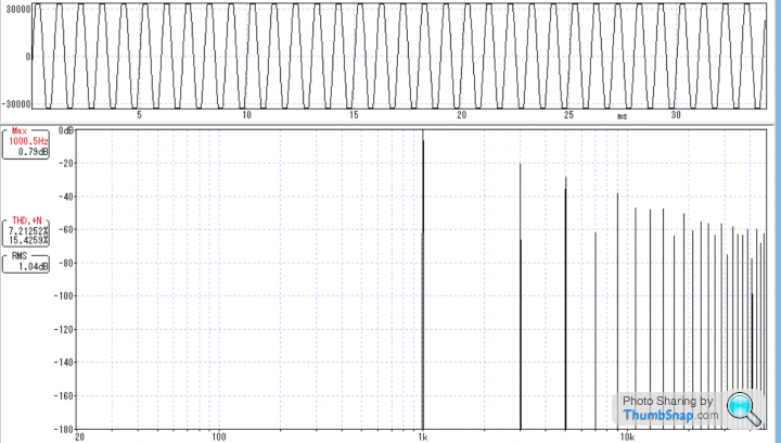
And here's an FFT of an unclipped file. (-1dB)

Edited by TonyRPH on Wednesday 12th April 08:10
robinessex said:
Debunking the Digital Audio Myth: The Truth About the 'Stair-Step' Effect
https://www.youtube.com/watch?v=cD7YFUYLpDc
That's an interesting video.https://www.youtube.com/watch?v=cD7YFUYLpDc
As I understand it - it's oversampling that smoothes the stair steps.
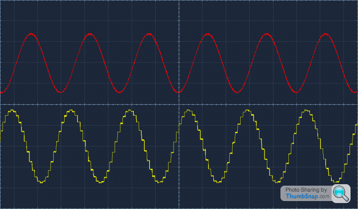
Here's a screenshot of my 'scope - one channel is an oversampling DAC, the other is a non oversampling DAC.
The stair step effect is clearly visible with the non oversampling DAC.
OutInTheShed said:
What's that ? A four bit DAC or a very small signal? Or maybe its a bigger signal but very high frequency, the kind of thing that's not exactly common in music apart from Ted Nugent overdoing the feedback?
It's meaningless without the amplitude and frequency being known.
It's a 16 bit DAC (TDA1543) and the signal was a 1kHz -1dB (the level is from memory but is the level I usually test at).It's meaningless without the amplitude and frequency being known.
OutInTheShed said:
If you put a 'non oversampled' DAC output into an ideal analogue filter, all the little stair-steps will be filtered out.
They are above the audio frequency range.
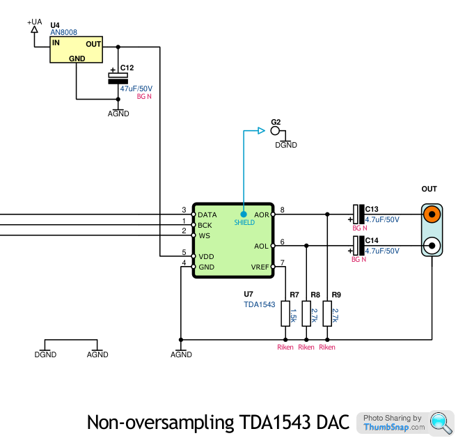
This particular DAC (using a TDA1543) uses a simple (passive) I/V converter which consists of a resistor and capacitor, which does little to 'smooth' the waveform.They are above the audio frequency range.
There is no digital filtering / oversampling.
OutInTheShed said:
An over-sampled DAC basically just makes the DAC artefacts higher in frequency making them easier to filter out with a simpler analogue filter which will have less effect on phase towards the top of the audio band.
Where it gets interesting is when a DAC with little or no oversampling has a poor analogue filter after it, allowing high frequency artefacts or spurious or whatever to enter the amplifier. A lot of amps don't seem to be well specified for rejecting such signals which may have effects on how the amp behaves in the audio band.
Maybe this explains why some amps which are near-perfect in there paper specs in the audio band sound different?
NON O/S DACs do output a lot of high frequency junk, which is known to upset some amps.Where it gets interesting is when a DAC with little or no oversampling has a poor analogue filter after it, allowing high frequency artefacts or spurious or whatever to enter the amplifier. A lot of amps don't seem to be well specified for rejecting such signals which may have effects on how the amp behaves in the audio band.
Maybe this explains why some amps which are near-perfect in there paper specs in the audio band sound different?
I can't think I've ever seen a well designed 'modern' DAC outputting HF junk, unless there is some fault somewhere.
Additionally, most modern DACs ultimately use an analogue filter to buffer the DAC and define output levels whilst tailoring the frequency response to the manufacturer's optimum desired response curve (and in some cases even tailored to provide a 'house' sound).
A couple of my DACs have switchable digital filters, and whilst the effects are easily measured, it's quite difficult to hear a great deal of difference.
EDIT: Found the schematic for the DAC I built. The digital data was provided by a CS8412 SPDIF receiver chip. The DAC was simplicity itself.
It sounded nasty though!
Edited by TonyRPH on Friday 9th June 17:53
OutInTheShed said:
'stuff'
The waveform gets worse as the frequency rises too of course..!These were quite popular back in the mid noughties.
These and R-2R DACs (both still have a limited following, and a couple of manufacturers are actually making R-2R DACs).
I never bought into the sound of either however - especially the NON O/S DACs which always sound hard to my ears.
There are some hobbyists out there that even run the TDA1541 in NON O/S mode, thinking that it sounds better...
Dylano said:
I'm no aficionado when it comes to all things hifi but I spotted these on FB Marketplace for a tenner and thought they looked interesting, I thought they were relatively modern but apparently they're 'vintage' and date back to the 90's.
I'm seeing them on ebay for £50 - £90 but none of those are complete, unused and still with their original box like mine.
Have I snagged a bargain or are the ones on ebay at delusional asking prices?
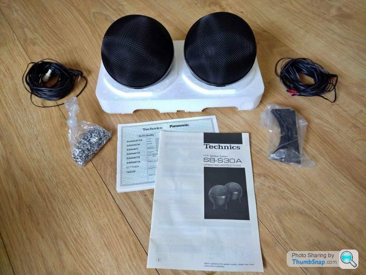

I see you have the user manual - would you mind posting a picture of the specifications page, so I can add the data to my Vintage Technics website?I'm seeing them on ebay for £50 - £90 but none of those are complete, unused and still with their original box like mine.
Have I snagged a bargain or are the ones on ebay at delusional asking prices?
Thanks!


Deranged Rover said:
But that's a calculation for continuous operation, which is completely unrealistic unless you happen to like listening to white noise or sine waves.
I have a pair of active loudspeakers in my lounge. Each has 13 amplifier modules in with a total power output of 8200W, however they plug into a 13A socket and I have never blown any fuses or tripped any breakers when running them at levels that make my eyeballs vibrate and things upstairs rattle.
There's a very big difference between running something flat out continuously and requiring very short term bursts of high power.
Ignoring the 'anti techie' brigade for a moment;I have a pair of active loudspeakers in my lounge. Each has 13 amplifier modules in with a total power output of 8200W, however they plug into a 13A socket and I have never blown any fuses or tripped any breakers when running them at levels that make my eyeballs vibrate and things upstairs rattle.
There's a very big difference between running something flat out continuously and requiring very short term bursts of high power.
13 amplifier modules per speaker - that doesn't add up for a stereo pair? It's either 12 or 14 (unless you've neglected to mention a sub of course).
Also - are these Class D or A/B (or G?).
Additionally, in an average room with average efficiency speakers (~90 db per M per 1 watt), it doesn't take a huge amount of watts to create a big noise.
AdeTuono said:
I thought that was the point of the entire thread...isn't there an equivalent for discussing all the minute, pointless b ks?
ks?
A new thread could probably be started, however the context would be lost.ks?A slight thread deviation now and then is harmless, if you don't like what you see, simply scroll on by...
And as the thread OP I believe I have the right to allow the occasional diversion.
Lol @ the comments guys.
Perhaps you should just chill.
It may not be interesting you, but it is to me.
There are plenty of threads that go off on a tangent for a few posts and then get back on track again - it's just the nature of things.
I don't know why you're getting so upset about it.
Perhaps you should just chill.
It may not be interesting you, but it is to me.
There are plenty of threads that go off on a tangent for a few posts and then get back on track again - it's just the nature of things.
I don't know why you're getting so upset about it.
Revisiting the Analog Domain Audio Apollo amp.
The rear panel sports a standard 13A IEC socket.
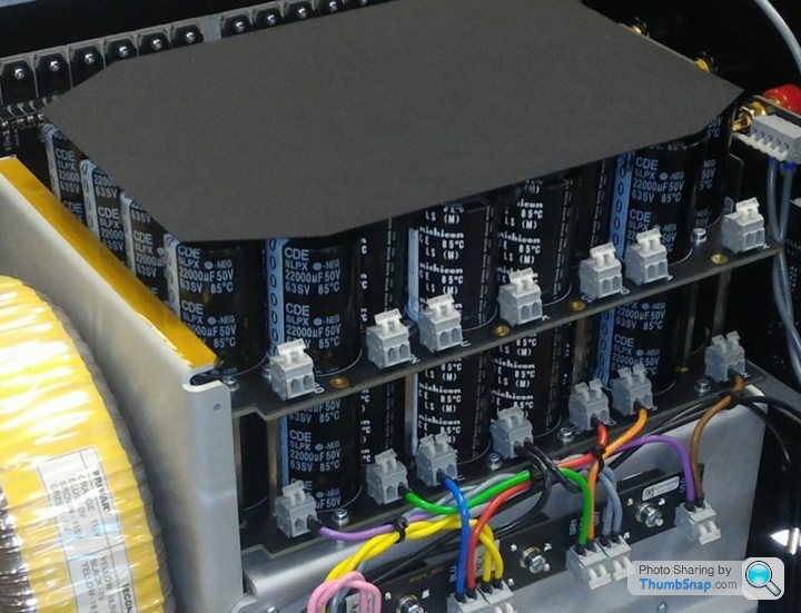
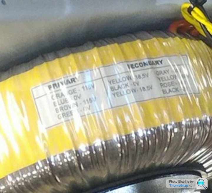
Assuming the transformer on view is the only one (and even allowing for scale) it doesn't look as big as one would expect, unless there's a second one lurking beneath the bank of smoothing caps (which I doubt, as the transformer has several secondaries listed, but unfortunately I can't see what the additional secondary voltages are).
And possibly ~24x 22000uF / 50v caps per rail? If the PSU is only 50-0-50 how are they getting so much power, as even in bridged mode it wouldn't achieve 4kW (even peak).

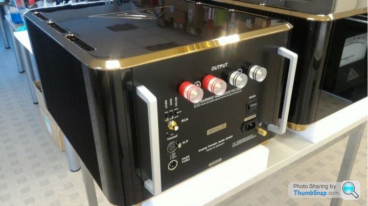
The rear panel sports a standard 13A IEC socket.
Assuming the transformer on view is the only one (and even allowing for scale) it doesn't look as big as one would expect, unless there's a second one lurking beneath the bank of smoothing caps (which I doubt, as the transformer has several secondaries listed, but unfortunately I can't see what the additional secondary voltages are).
And possibly ~24x 22000uF / 50v caps per rail? If the PSU is only 50-0-50 how are they getting so much power, as even in bridged mode it wouldn't achieve 4kW (even peak).
Edited by TonyRPH on Wednesday 23 August 11:29
Deranged Rover said:
TonyRPH said:
Ignoring the 'anti techie' brigade for a moment;
13 amplifier modules per speaker - that doesn't add up for a stereo pair? It's either 12 or 14 (unless you've neglected to mention a sub of course).
Yes it does. The left speaker has 13 amplifier modules built into it (one for each of the 13 drive units) and the right speaker has 13 amplifier modules in it. Total of 26 across the two speakers, making 16,400W in my lounge (or not...).13 amplifier modules per speaker - that doesn't add up for a stereo pair? It's either 12 or 14 (unless you've neglected to mention a sub of course).
I'm not looking to be critical - I'm just fascinated by the sheer amount of drive units per speaker.
I remember the old IMF TL's from the 70's with as many as 4 to 6 drive units per side.
Designing the (passive) crossover for phase linearity must have been interesting.
911hope said:
Perhaps someone who understands basic electric theory can calculate the max power an amp with +/- 50 v rails can deliver into 8 and 4 ohms.
Any calculations based around an unknown design are purely hypothetical but...The smoothing caps are rated at 50vDC and if the designer was sensible enough, would be running them somewhat below 50v - but let's assume they are running at 45-0-45
P = Vrail^2 / (2 X Impedance) = W
Therefore (and not allowing for losses) I would expect the amp to yield ~ 126w / 8 ohms and ~253w / 4 ohms
If it's a bridged design, then we could expect approx. 4x that so 500w / 8 ohms - 1kW / 4 ohms
All figures RMS.
Did I pass the test?
probably not!

Gassing Station | Home Cinema & Hi-Fi | Top of Page | What's New | My Stuff