Ask an Electrician anything...
Discussion


As someone who deals with electrical safety , I will tell you that those pen sticks are only to be used for tracing purposes.
They SHOULD NOT be used to prove or confirm dead any electrical circuit. especially one that your about to put your fingers on.
If undertaking any electrical work,
Identify the circuit or equipment to be worked on.
Isolate and secure the point of isolation. Also if doing it properly you would be fitting a caution sign 'Do Not Touch' on your point of isolation.
Once secured then you have to prove / confirm dead. prove or confirm is exactly the same thing, only difference is to do with safety documentation, and you wont be doing that.... But you still need to prove / confirm dead and that is by the use of an appropriate testing device to GS38 standards that gives a positive identification of live equipment.
You would test the tester before doing the prove/confirm then test the tester right after.
I have a huge dislike for tester screwdrivers or non contact testers. Mains is dangerous, and it has the capacity to kill you. too many lulled into a false sense of security.
This might be a question more appropriate for the EV section of the forum, but I am unsure what I need here from an electrical perspective.
I would like an EV compatible 3 pin plug on the front of the house (such as this: https://www.screwfix.com/p/masterplug-ip66-13a-1-g... - we only have a small capacity EV so don't really need a fast charger, but I'm reluctant to use the granny lead off one of our garage sockets long term as I don't know what the wiring is like upstream of that.
I understand that even for the above linked RCBO protected EV socket, I'd also need (as found in a post on another forum):
Additionally, second question would be what type of cable I'd need to run from the CU to the socket - as it's a 13amp socket (10amp continuous with the granny charger), I was thinking just 2.5mm2 T&E in conduit, but not sure if I need to go more chunky in terms of cabling here. Shouldn't think it has to be armoured either as it would run along the garage wall (internally).
Caveat: I am not a sparky, and wouldn't be touching the CU or anything else live without a professional here - I just like geeking out on it all and am happy to run cables and conduit etc. in advance of a proper sparky turning up.
I would like an EV compatible 3 pin plug on the front of the house (such as this: https://www.screwfix.com/p/masterplug-ip66-13a-1-g... - we only have a small capacity EV so don't really need a fast charger, but I'm reluctant to use the granny lead off one of our garage sockets long term as I don't know what the wiring is like upstream of that.
I understand that even for the above linked RCBO protected EV socket, I'd also need (as found in a post on another forum):
- A specific final circuit for the charge point or socket - no problem, can run an independent cable to it from the CU which is in the garage
- Over current protection for the cable and the equipment- normally a 32A MCB at the source of the circuit. - again, fine, spare way available in the CU
- Double pole residual current protection at 30mA AC to protect against electric shock from direct contact - covered by the Type A RCBO in the above linked socket
- Protection against DC direct contact and prevention of potential blinding of type AC RCDs elsewhere in the installation. Can be incorporated into the AC residual protection by using a type B device or provided within a permanently connected EVSE - covered by the Mennekes granny charger itself
- If you have a TN-C-S (also known as PME) supply, you need a method of protection against the shock risk from open PEN faults. There are 5 ways of doing this, each with their own disadvantages. The risk only exists outside so if you go down the protection device route rather than the earth rod route, it’s only necessary to protect the EVSE circuit. Using such a device to protect other circuits inside the house is unnecessary and would mean buying a higher rated and hence more expensive (and maybe non existent) devices
Additionally, second question would be what type of cable I'd need to run from the CU to the socket - as it's a 13amp socket (10amp continuous with the granny charger), I was thinking just 2.5mm2 T&E in conduit, but not sure if I need to go more chunky in terms of cabling here. Shouldn't think it has to be armoured either as it would run along the garage wall (internally).
Caveat: I am not a sparky, and wouldn't be touching the CU or anything else live without a professional here - I just like geeking out on it all and am happy to run cables and conduit etc. in advance of a proper sparky turning up.
ccr32 said:
This might be a question more appropriate for the EV section of the forum, but I am unsure what I need here from an electrical perspective.
I would like an EV compatible 3 pin plug on the front of the house (such as this: https://www.screwfix.com/p/masterplug-ip66-13a-1-g... - we only have a small capacity EV so don't really need a fast charger, but I'm reluctant to use the granny lead off one of our garage sockets long term as I don't know what the wiring is like upstream of that.
I understand that even for the above linked RCBO protected EV socket, I'd also need (as found in a post on another forum):
Additionally, second question would be what type of cable I'd need to run from the CU to the socket - as it's a 13amp socket (10amp continuous with the granny charger), I was thinking just 2.5mm2 T&E in conduit, but not sure if I need to go more chunky in terms of cabling here. Shouldn't think it has to be armoured either as it would run along the garage wall (internally).
Caveat: I am not a sparky, and wouldn't be touching the CU or anything else live without a professional here - I just like geeking out on it all and am happy to run cables and conduit etc. in advance of a proper sparky turning up.
If running a dedicated circuit and using a 32amp breaker, you will need to chunk up to 4mm T+E. 2.5mm is only rated to about 24-26 amps when in radial form. If you change the breaker to 16amp, you can use 2.5mm (or even 1.5mm). I would like an EV compatible 3 pin plug on the front of the house (such as this: https://www.screwfix.com/p/masterplug-ip66-13a-1-g... - we only have a small capacity EV so don't really need a fast charger, but I'm reluctant to use the granny lead off one of our garage sockets long term as I don't know what the wiring is like upstream of that.
I understand that even for the above linked RCBO protected EV socket, I'd also need (as found in a post on another forum):
- A specific final circuit for the charge point or socket - no problem, can run an independent cable to it from the CU which is in the garage
- Over current protection for the cable and the equipment- normally a 32A MCB at the source of the circuit. - again, fine, spare way available in the CU
- Double pole residual current protection at 30mA AC to protect against electric shock from direct contact - covered by the Type A RCBO in the above linked socket
- Protection against DC direct contact and prevention of potential blinding of type AC RCDs elsewhere in the installation. Can be incorporated into the AC residual protection by using a type B device or provided within a permanently connected EVSE - covered by the Mennekes granny charger itself
- If you have a TN-C-S (also known as PME) supply, you need a method of protection against the shock risk from open PEN faults. There are 5 ways of doing this, each with their own disadvantages. The risk only exists outside so if you go down the protection device route rather than the earth rod route, it’s only necessary to protect the EVSE circuit. Using such a device to protect other circuits inside the house is unnecessary and would mean buying a higher rated and hence more expensive (and maybe non existent) devices
Additionally, second question would be what type of cable I'd need to run from the CU to the socket - as it's a 13amp socket (10amp continuous with the granny charger), I was thinking just 2.5mm2 T&E in conduit, but not sure if I need to go more chunky in terms of cabling here. Shouldn't think it has to be armoured either as it would run along the garage wall (internally).
Caveat: I am not a sparky, and wouldn't be touching the CU or anything else live without a professional here - I just like geeking out on it all and am happy to run cables and conduit etc. in advance of a proper sparky turning up.
In terms of earth rod, use it’s fine if the resistance is low enough. Otherwise, you can get pen fault detection devices that work on PME.
Personally, the main issue with granny charges and normal sockets is heat as they are only designed for 10amp continuous / 13 amp peak. If it was me, I would just spur off the main ring and use an outside socket with the draw turned down to 10amp on the car (or an EV specific 13amp socket). As the EV charger is plug in equipment, regs wise, there is no issue. There is risk, but if going to the effort of a dedicated supply, just get a 7kwh charger off eBay and do a proper install. I think I paid £200 for my Easee charger…
Regbuser said:
..4mm T&E..
But we don't know:
Length of run
Fixing method
Any adverse conditions
So that may not be the correct cable
bingo.... peeps often forget that.... But we don't know:
Length of run
Fixing method
Any adverse conditions
So that may not be the correct cable
and cable needs to be right, no excessive volt drop - its stipulated in the requirements.
id go for a pme fault detector, dont want to depend on the one in the charger itself.
ammendment 2 allows install of a local earth rod and to connect that to your main earth terminal.
Regbuser said:
..4mm T&E..
But we don't know:
Length of run
Fixing method
Any adverse conditions
So that may not be the correct cable
In my case, it would be under 10m run, and in the aforementioned conduit which would be fixed to the inside of the garage wall. But we don't know:
Length of run
Fixing method
Any adverse conditions
So that may not be the correct cable
All that said, and given the earlier suggestion (seeing as my preference would still be to run a new cable from the CU), I’ve now started up looking up ‘proper’ 7kw chargers and going the whole hog instead.
Edited by ccr32 on Saturday 6th April 17:06
dhutch said:
So what sort of tester do you use?
What anyone playing with electric should be using - a proper voltage tester (and according to protocol, used in conjunction with a proving unit). They start about £30, but if anyone wants a cheap basic one, I have a Klein ET45 which is well reviewed and only cost me about a tenner from Amazon. Works well and is tiny - I use it when I can’t be arsed to get the bigger one out

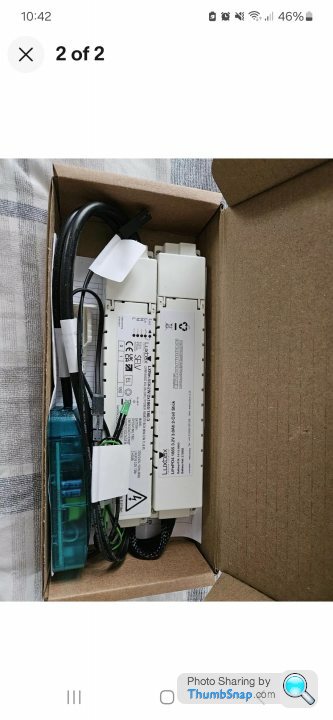
Normally fitted by a sparkie so not something bought by a DIYer? Unknown provenance so people not as willing to take the risk? What’s the shelf life of the batteries? That the installation date sticker goes from 2018 to 2024 suggests they have been sitting around for a while?
You really should list the part numbers so the listing gets found during a search. Leaving them out is just… lazy… and not helping you sell them.
You really should list the part numbers so the listing gets found during a search. Leaving them out is just… lazy… and not helping you sell them.
AW10 said:
Normally fitted by a sparkie so not something bought by a DIYer? Unknown provenance so people not as willing to take the risk? What’s the shelf life of the batteries? That the installation date sticker goes from 2018 to 2024 suggests they have been sitting around for a while?
You really should list the part numbers so the listing gets found during a search. Leaving them out is just… lazy… and not helping you sell them.
Cheers, have now added the part number to the title and description. You really should list the part numbers so the listing gets found during a search. Leaving them out is just… lazy… and not helping you sell them.
guitarcarfanatic said:
dhutch said:
So what sort of tester do you use?
What anyone playing with electric should be using - a proper voltage tester (and according to protocol, used in conjunction with a proving unit). They start about £30, but if anyone wants a cheap basic one, I have a Klein ET45 which is well reviewed and only cost me about a tenner from Amazon. Works well and is tiny - I use it when I can’t be arsed to get the bigger one out
But the key for ultimate safety is test the tester, test the circuit, test the tester and any voltmeter can do that.
But I bet very few of us do it at home

after some knowledge here on what my options are.........
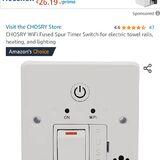
I wish to fit a couple of outside lights in my garden, I wish to control them from a spare switch already in the wall by the back door
I have power in the shed(s) at the bottom of the garden but nothing else, I dont wish to dig up the patio or run any wiring down the garden if possible, failry sure there is a wiring in place under/at the side of the patio from said switch that could be directed to water proof box etc
is there a wifi/radio signal relay device I can use ?
at the moment it appears a wifi plug in the shed and just usiing an app is the front runner but would like to use the switch by the back door if possible
Thanking you
AW10 said:
Normally fitted by a sparkie so not something bought by a DIYer? Unknown provenance so people not as willing to take the risk? What’s the shelf life of the batteries? That the installation date sticker goes from 2018 to 2024 suggests they have been sitting around for a while?
Also most DIYers are going to be adding maybe one or two, not four?Steve Campbell said:
Is there a simple way to find out why no power is being fed to a light ?
Here's the problem > When we moved in 17 years ago, I had a large drinks cabinet for the dining room. Dining room had 3 uplighters. I removed the uplighter and made safe the wires on one of them where I wanted to put the cabinet against the wall. No idea if it was working at the time as this was on the day of moving in.
17 years later, the cabinet has gone and new uplighters now fitted....but the one that was blanked off doesn't work !
I have an electrician coming around next week anyway but was just wondering. Electrician also going to fix my idiot mistake of replacing other lights and not checking what wires connected to what before disconnecting the light.....so I have 4 wires coming in consisting of 4 reds, 3 blacks, one blue and 2 earths !.......and have no idea which one is the switch etc etc ! Just so happens the first one I took apart is the primary link to all the others (4 other lights and 2 other rooms !). Oh well........
All's well that ends well. The electrician had an easy job and probably had a chuckle at my ineptitude with the lights. He got his call out fee and had it all sorted in 20 mins. Quickly figured out the old pendant light wiring and got it sorted. The non-working light ? Whoever had the house before us had disconnected that light in one of the 2 switches and just taped it off ! No idea why. Anyway, always check the switch first :-). I wouldn't have known which wire to put where. At least I knew when to call in a professional !Here's the problem > When we moved in 17 years ago, I had a large drinks cabinet for the dining room. Dining room had 3 uplighters. I removed the uplighter and made safe the wires on one of them where I wanted to put the cabinet against the wall. No idea if it was working at the time as this was on the day of moving in.
17 years later, the cabinet has gone and new uplighters now fitted....but the one that was blanked off doesn't work !
I have an electrician coming around next week anyway but was just wondering. Electrician also going to fix my idiot mistake of replacing other lights and not checking what wires connected to what before disconnecting the light.....so I have 4 wires coming in consisting of 4 reds, 3 blacks, one blue and 2 earths !.......and have no idea which one is the switch etc etc ! Just so happens the first one I took apart is the primary link to all the others (4 other lights and 2 other rooms !). Oh well........

Actual said:
FLUKE AC NON-CONTACT VOLTAGE DETECTOR PEN 1000V AC
.screwfix.com/p/fluke-ac-non-contact-voltage-detector-pen-1000v-ac/85949
Unlike other pen type detectors this one is more safe to use and will glow red when you position it next a live wire.
Just so you know it is working it is advisable to make sure it is turned on and check a known live wire before and after checking the wire being tested.
More safe?.screwfix.com/p/fluke-ac-non-contact-voltage-detector-pen-1000v-ac/85949
Unlike other pen type detectors this one is more safe to use and will glow red when you position it next a live wire.
Just so you know it is working it is advisable to make sure it is turned on and check a known live wire before and after checking the wire being tested.
Edited by Actual on Thursday 4th April 11:34

Safe doesn't belong in the sentence. Comparing glow sticks and neon screwdrivers on safety grounds is akin to comparing stringfellow and Andrew Tate as to who is a more appropriate first date for your daughter.
Gassing Station | Homes, Gardens and DIY | Top of Page | What's New | My Stuff