Where to connect alternator voltage sensing wire
Discussion


Sorry, I should have been more clear. I have no loom, so all the wires must be installed. The alternator has a connector marked PLIS. P is not used. L (charge light) and I (+12V ignition) are no problem. The question is to where should I take the S wire.
The alternator's function is to maintain battery voltage at 13+V. It has to work harder when all loads are on but can take it easy when only ignition is working.
Alternator output increases / decreases depending on the voltage sensed at the S terminal. So from where will the alternator get the best measure to increase the charging rate with everything tuned on but decrease it when the only draw is ignition? At the battery or downstream after the load connections?
Thanks
JohnMcL.
Thanks for the replies. I continued hunting for info and found this.
http://www.pirate4x4.com/tech/billavista/Wiring/Pa...
http://www.pirate4x4.com/tech/billavista/Wiring/Pa...
The answer to my question is buried in the middle of Part 2. The key bits for me in laying out the wires are that the alternator output charging wire and the sensing wire should go to the same place and that the output charging wire should not go directly to the battery.
That’s what I will do unless someone comes up with a reasoned alternative.
Thanks
John McL.
http://www.pirate4x4.com/tech/billavista/Wiring/Pa...
http://www.pirate4x4.com/tech/billavista/Wiring/Pa...
The answer to my question is buried in the middle of Part 2. The key bits for me in laying out the wires are that the alternator output charging wire and the sensing wire should go to the same place and that the output charging wire should not go directly to the battery.
That’s what I will do unless someone comes up with a reasoned alternative.
Thanks
John McL.
Hi.
I have a home build car with an Escort alternator wired to a Lotus engine.
The alternator has 3 connections, 2 large and 1 small.
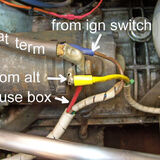
Some manufactures run smaller wires from both of the larger terminals but I have elected to use just one terminal and larger wire. (yellow)
The smaller connection runs to the ignition charging lamp (blue) and needs to be a bulb, not an LED. the other side of the bulb goes to earth. (-)
The starter motor solenoid has a very large wire from the battery positive terminal and to the same pole the yellow wire from the alternator
and the permanent live feed to the fuse box is connected. A wire is taken from the fuse box through the ignition key switch to the other side
of the solenoid. (brown)
Hope this helps
Paul G

I have a home build car with an Escort alternator wired to a Lotus engine.
The alternator has 3 connections, 2 large and 1 small.
Some manufactures run smaller wires from both of the larger terminals but I have elected to use just one terminal and larger wire. (yellow)
The smaller connection runs to the ignition charging lamp (blue) and needs to be a bulb, not an LED. the other side of the bulb goes to earth. (-)
The starter motor solenoid has a very large wire from the battery positive terminal and to the same pole the yellow wire from the alternator
and the permanent live feed to the fuse box is connected. A wire is taken from the fuse box through the ignition key switch to the other side
of the solenoid. (brown)
Hope this helps
Paul G
Take it to a main spur (your fusebox or similar) where there's a lot of load and similar sized wiring coming off - it's only really there to compensate for voltage drop on your other wiring so should be a similar length and gauge to most of them and taking a reference from their source.
Jakg said:
Assuming appropriately sized cable, the voltage should be the same everywhere in the system. If it's not, you probably have a problem.
If this were the case there would be no need of a voltage sense wire (which every modern car will have). The voltage is never the same everywhere, even the steel bodyshell can suffer from voltage drop at high currents.Mr2Mike said:
If this were the case there would be no need of a voltage sense wire (which every modern car will have). The voltage is never the same everywhere, even the steel bodyshell can suffer from voltage drop at high currents.
Yes, the above is correct. If you mount 10000 starter motors to the front of the body and the battery earth to the rear of the body, when operating these starter motors with heavy duty switching gear the body will glow a dim orange colour and a volt drop can be measured from front to back.It is best practice to only use 1 starter motor if the battery is earthed in the boot and the engine is in the front otherwise the paint will peel off the bodywork when cranking
Penelope Stopit said:
That’s what I will do unless someone comes up with a reasoned alternative.
Connect the S Wire to the main positive wire at the starter motor as there is true battery voltage to be had there
You don't want to connect to the starter motor at all because the wiring gauge to the starter is not representative for the bulk of your loom. If you're going to do that you may as well not use the sensing wire at all and just short it inside the alternator.Connect the S Wire to the main positive wire at the starter motor as there is true battery voltage to be had there
PhillipM said:
You don't want to connect to the starter motor at all because the wiring gauge to the starter is not representative for the bulk of your loom. If you're going to do that you may as well not use the sensing wire at all and just short it inside the alternator.
The sense wire is used to account for the voltage drop between alternator and battery to ensure an accurate charging voltage, i.e. it should be connected to a point which is most representative of battery voltage. The battery terminal is obviously optimal, but the starter solenoid is a reasonable location since it is connected to the battery via very heavy gauge cable.Penelope Stopit said:
Yes, the above is correct. If you mount 10000 starter motors to the front of the body and the battery earth to the rear of the body, when operating these starter motors with heavy duty switching gear the body will glow a dim orange colour and a volt drop can be measured from front to back.
It is best practice to only use 1 starter motor if the battery is earthed in the boot and the engine is in the front otherwise the paint will peel off the bodywork when cranking
I have no idea what you are talking about, which is a coincidence as clearly neither do you.It is best practice to only use 1 starter motor if the battery is earthed in the boot and the engine is in the front otherwise the paint will peel off the bodywork when cranking
That doesn't help you if your starter feed piggybacks from the alternator as many do though, as you're still suffering the voltage drop down the main feed - you're better off either straight to the battery or straight to the main fusebox, with a fuse.
Edited by PhillipM on Wednesday 13th January 16:27
Mr2Mike said:
If this were the case there would be no need of a voltage sense wire (which every modern car will have). The voltage is never the same everywhere, even the steel bodyshell can suffer from voltage drop at high currents.
even the steel bodyshell can suffer from voltage drop at high currentsThe above comment from you is what I am on about. Now who doesnt know what they are talking about????
Penelope Stopit said:
even the steel bodyshell can suffer from voltage drop at high currents
The above comment from you is what I am on about. Now who doesnt know what they are talking about????
You, unless you have a superconducting body on your car?The above comment from you is what I am on about. Now who doesnt know what they are talking about????
Edited by Mr2Mike on Wednesday 13th January 23:15
OK everyone - I think I have it. Thanks to all, even those who do not understand Ohm's law or that all conductors have resistance and therefore voltage drop. I have found a good explanation of right/wrong sensor wire connection (and why) at
http://wilbo666.pbworks.com/w/page/39441708/Toyota... There is an informative picture if you scroll down.
But I still recommend reading Part 2 in the link I posted back near the top.
Thanks again.
http://wilbo666.pbworks.com/w/page/39441708/Toyota... There is an informative picture if you scroll down.
But I still recommend reading Part 2 in the link I posted back near the top.
Thanks again.
And in that above link it reads
The voltage at the battery is the main parameter that the regulator uses to control / regulate the alternator output.
Hence anyone having a dabble with electrics that does not understand that the main battery positive wire at the starter motor is true battery voltage, should not be having a dabble
The voltage at the battery is the main parameter that the regulator uses to control / regulate the alternator output.
Hence anyone having a dabble with electrics that does not understand that the main battery positive wire at the starter motor is true battery voltage, should not be having a dabble
PhillipM said:
Penelope Stopit said:
That’s what I will do unless someone comes up with a reasoned alternative.
Connect the S Wire to the main positive wire at the starter motor as there is true battery voltage to be had there
You don't want to connect to the starter motor at all because the wiring gauge to the starter is not representative for the bulk of your loom. If you're going to do that you may as well not use the sensing wire at all and just short it inside the alternator.Connect the S Wire to the main positive wire at the starter motor as there is true battery voltage to be had there
Gassing Station | Home Mechanics | Top of Page | What's New | My Stuff