Replacing a heater resistor pack with a DC PWM controller
Discussion


Hi all, I am hoping that an electronics guru can help me out here. My question relates to a Lotus, but it's general electronics info I am after so hopefully this is the best forum to choose? (It's not a good fit for any of the Technical forums either.)
My Lotus has a known fault, whereby the heater resistor pack (which is buried deep in the front of the car) fills up with water and fails. Getting to it to replace it means taking the front clam off, discharging and removing aircon components, and costs a lot of £ or hrs depending on how hands-on the owner is.
It is possible to access the last piece of fan wiring, which takes 12V from the resistor pack to the fan, and therefore to bypass the failed pack and provide simple on/off control. I saw a reference in an American forum which suggested using a DC 12V 30A pulse width modulated motor controller in place of the fan resistor pack. This idea is attractive, because using resistors to limit the motor speed generates a lot of heat (hence Lotus's decision to bury the resistor pack in the fan intake tract, so that it's always in airflow whilst in operation). I am hoping that a PWM controller will run a lot cooler, so that it could be mounted in a more accessible location for installation (and any required maintenance).
I know a bit about electronics but I am no expert, so I was hoping someone could answer the four questions I have:
1) Will a PWM controller run cool enough to avoid the need for constant airflow? I guess the answer is "maybe, depending on design and current draw" - if so, how can I ensure cool operation in the smallest possible package?
2) These units seem to do the job I'm after, any comments on their suitability or suggestions of better alternatives?
https://www.amazon.co.uk/300w-Motor-Speed-Control-...
https://www.4qd.co.uk/product/sst/ (too complicated for my needs?)
3) I would like to retain the three steps for speed control, rather than having a constantly variable potentiometer. I think I just need a voltage divider circuit hung off the back of my existing four-position dashboard switch, is that right?
4) I can only access the +12V wire going to the fan, not its earth cable point. The PWM controllers above have terminals for both motor +ve and -ve. Should I connect the controller's motor -ve terminal to earth?
Although none of this is simple, I am hoping that I can find a working solution which provides benefit to other S2 Elise/Exige owners. Thanks in advance for any help!
Difficult to give a definitive reply without checking how it is all connected.... but... you seem to be correct with everything.
1) I would expect it to run quite a bit cooler, but I wouldn't be comfortable burying it somewhere that heat couldn't dissipate, or where there is a heat source (like under the bonnet). You can't see inside those controllers, but the spec doesn't tell you the temperature or efficiency at 100% duty cycle so it'll be a guess.
2) The one from Amazon looks like it would do the job fine, assuming your values are correct. I've bought very similar items, but not variable output, to use as power supplies for 3d printers.
3) Yes, that'd work. You might have to play with different resistor values to get the right steps in fan control that you want. If all the resistors are equal you might find the first step does nothing... the motor might not do much until the PWM duty cycle is higher. So you might have to use unequal resistor values to get fan switch positions that match the workable PWM range. You could play with the variable resistor and a multimeter to work out the resistor values you'd need.
4) This would work on the assumption that the fan is chassis grounded, which it likely is. Can you check? I'd assume it would be, but worth checking.
As above, I think the principle is sound but working out exactly what PWM outputs you want to give a nice spread of fan speeds will require some experimentation.
Another option would be to get a programmable control which can operate on multiple digital input pins and use the existing lines from the switch to drive the control GPIOs then you can use code to tweak the fan speeds. You'd ideally want a controller which could cope with 12 volt inputs though. I wonder if there's an arduino shield which will do the job?
ETA: The existing resistor pack has no negative/earth supply so presumably the fans are chassis earthed.
Edited by kambites on Monday 14th May 16:12
I assume the original solution has multiple high current wires from the switch to the resister pack, and one output from that to the fan.
I'd suggest replacing that resister pack with a much smaller voltage divider. It would only need to carry a few tens of mA so could be heat shrink wrapped and sealed away anywhere convenient. Take the output from that to the fan (last leg of the voltage divider will be a resistor pulled down to the fan -ve) to give you a control voltage signal at the fan. Use that to control a speed controller at the fan. It shouldn't need to dissipate a lot of heat - if you attach it to the inside of a waterproof metal box and put that somewhere near the fan I expect that will be all the cooling it needs. This leaves all the switch wiring intact and means all the changes are around the fan. The only significant wiring addition will be a separate fused 12V supply to the motor controller at the fan.
I was considering something similar (using a BLDC motor) for the engine cooling fan and EWP - but not on a Lotus.
If the fan is for cabin cooling, why isn't the resister inside the fan unit? That seems like the obvious place to put it. If the fan unit is getting flooded, I'd see that as a problem in its own right that you need to solve.
Edited by GreenV8S on Monday 14th May 16:28
These "resistor packs" aren't actually usually just resistors. The famous 'hedgehog' resistors in the BMWs that are famous for blowing up... they're actually a fan controller, not a simple resistor.
You can't just use a few resistors, as these resistors would have to dissipate any of the power not going to the fan... hence why it was designed to be cooled in the first place.
The OP is on the right track with those controllers... it'll just take some fiddling and experimentation to get the control resistors to the correct values (the control resistors won't have to dissipate any significant heat at all).

GreenV8S said:
I assume the original solution has multiple high current wires from the switch to the resister pack, and one output from that to the fan.
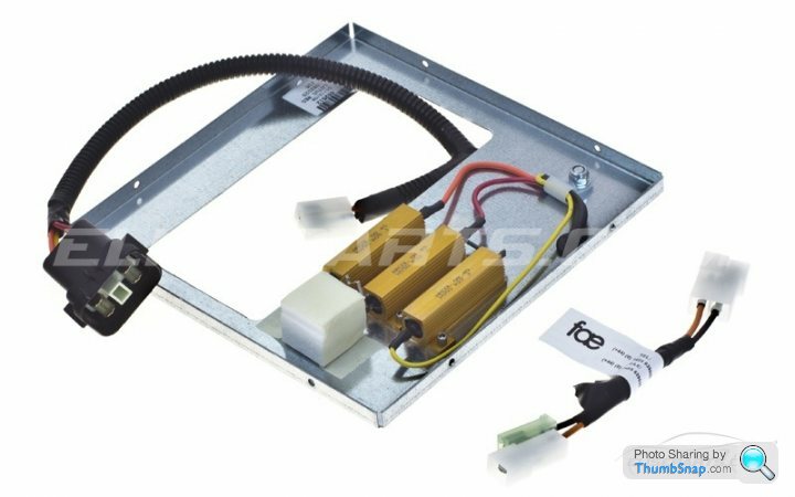
Yes, three high current 12v lines in, one variable voltage line out. Lotus actually redesigned and relocated the resistor pack in later S2s and the later pack is retrofittable so that's by far the easiest solution. The later unit is actually three separate resistors and has a heat-sink on each resistor which presumably means it doesn't need to be in the air-flow:
original:

replacement:

My original went at about three years old. The replacement has been on for over ten years now and is still fine.
Edited by kambites on Monday 14th May 19:22
kambites said:
Lotus actually redesigned and relocated the resistor pack in later S2s and the later pack is retrofittable so that's by far the easiest solution. The later unit is actually three separate resistors and has a heat-sink on each resistor which presumably means it doesn't need to be in the air-flow:
Those resistors with heatsinks are in the airflow or am I mistaken?The resistors get very hot unless they are in an airflow
https://wiki.seloc.org/a/Resistor_pack

To the best of my knowledge, Penelope is right Kambites, the new resistor assembly solves the water ingress issue but is located in the same spot and requires the same cooling. Thank you everyone for all of the replies, it sounds like I am on the right track here, so I have ordered the Amazon PWM controller. There don't appear to be any UK stockists so I have a two week wait for it to come from China!
There are some good suggestions about using a separate fan to cool the resistor pack/controller, I hadn't thought of that but the issue is lack of space. There are no hiding places behind the dash for that kind of arrangement and I want a solution that keeps the car looking 100% factory.
My plan is (once the controller has arrived) to connect everything on flying leads, and then test temps etc during sustained running, and to establish what resistors I need for the voltage divider circuit. I will try to update this thread once I have made some progress, it may be of benefit to others.
Everyone to their own. I would use resistors mounted to a panel very similar to the Lotus Modification and add this type of cooling fan rather than get involved with controllers https://www.amazon.com/Xscorpion-FAN61-12-Volt-6-I...
The end product will be slim enough to find a home for it somewhere
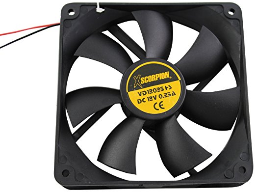
The end product will be slim enough to find a home for it somewhere


Gassing Station | Home Mechanics | Top of Page | What's New | My Stuff