Wiring loom design help
Discussion


I've got to redo part of a 12 volt kit car wiring loom and need a spot of technical help here to do it properly.
Items in question are the tail and number plates lights but I'll need to follow the same process for the brake lights.
Intent is to have the first of the four lights (all lights will be 5W) fed from a single cable (large diameter) but the subsequent items using thinner diameter as the distance and loads (I think!) are less.
They won't be in series as the cable will split at each light to feed on to the next with each light having a separate earth.
Initial light is 3.5m from 12v source with the other three each spaced approximately 0.8m further down the line.
My understanding is as follows :-
The feed cable to the first component needs to be calculated using distance (to first light from source) and amperage (of all four lights) plus cable resistance of the selected wire to ensure voltage drop is acceptable.
The next light would be calculated similarly but you would use the shorter 0.8m distance from the first light, the amperage of only three lights plus cable resistance of the selected cable to ensure voltage drop is acceptable (thinner gauge cable).
Next two lights requirements would be calculated using further reduction in amperage for two and then one light.
Once the last item has been evaluated I can then work out the total voltage drop at the last light to ensure that falls within an acceptable range. If it's too great then I could re-evaluate with a thicker gauge of cable.
The big question though is ..... have I got my maths process right?
Any help really appreciated on this one.
Tacchino said:
I've got to redo part of a 12 volt kit car wiring loom and need a spot of technical help here to do it properly.
Items in question are the tail and number plates lights but I'll need to follow the same process for the brake lights.
Intent is to have the first of the four lights (all lights will be 5W) fed from a single cable (large diameter) but the subsequent items using thinner diameter as the distance and loads (I think!) are less.
They won't be in series as the cable will split at each light to feed on to the next with each light having a separate earth.
Initial light is 3.5m from 12v source with the other three each spaced approximately 0.8m further down the line.
My understanding is as follows :-
The feed cable to the first component needs to be calculated using distance (to first light from source) and amperage (of all four lights) plus cable resistance of the selected wire to ensure voltage drop is acceptable.
The next light would be calculated similarly but you would use the shorter 0.8m distance from the first light, the amperage of only three lights plus cable resistance of the selected cable to ensure voltage drop is acceptable (thinner gauge cable).
Next two lights requirements would be calculated using further reduction in amperage for two and then one light.
Once the last item has been evaluated I can then work out the total voltage drop at the last light to ensure that falls within an acceptable range. If it's too great then I could re-evaluate with a thicker gauge of cable.
The big question though is ..... have I got my maths process right?
Any help really appreciated on this one.
Not sure what you're trying to achieve by way of saving to be honest.Items in question are the tail and number plates lights but I'll need to follow the same process for the brake lights.
Intent is to have the first of the four lights (all lights will be 5W) fed from a single cable (large diameter) but the subsequent items using thinner diameter as the distance and loads (I think!) are less.
They won't be in series as the cable will split at each light to feed on to the next with each light having a separate earth.
Initial light is 3.5m from 12v source with the other three each spaced approximately 0.8m further down the line.
My understanding is as follows :-
The feed cable to the first component needs to be calculated using distance (to first light from source) and amperage (of all four lights) plus cable resistance of the selected wire to ensure voltage drop is acceptable.
The next light would be calculated similarly but you would use the shorter 0.8m distance from the first light, the amperage of only three lights plus cable resistance of the selected cable to ensure voltage drop is acceptable (thinner gauge cable).
Next two lights requirements would be calculated using further reduction in amperage for two and then one light.
Once the last item has been evaluated I can then work out the total voltage drop at the last light to ensure that falls within an acceptable range. If it's too great then I could re-evaluate with a thicker gauge of cable.
The big question though is ..... have I got my maths process right?
Any help really appreciated on this one.
There are only a few gauges of cable available, so you may as well just wire it all in a suitable gauge. You won't save much weight or money trying to separate it all out....
You must also fuse it to protect the thinnest cable in the circuit - unless you plan to add a fuse at every point you go down a gauge.
So all in, just use a single gauge that is big enough.
Otherwise, yes you need to work out current capacity and voltage drop.
I think you're over-thinking the problem. Usually you'd daisy chain a single wire to all the lamps sized to suit the total current and total run length, or separate wires to each lamp if they needed to be fused separately. There's no need to finesse the wire size - just work out the minimum size and go for the next standard size up that you have available.
It's neither a "save money" or "save weight" scenario.
I have a piece of loom that is wrong to begin with and requires lots of changes to be made and the rest of the loom not looking exactly clever.
I want to be able to resolve the problems but do so in way that is a designed and understood solution.
As you say I can use larger cable throughout which will be satisfactory on the end section of the loom but I need to be certain that it won't cause upstream issues within the existing loom.
Currently I have two 0.5mm feeds powering four 5W lights.
Ideally this needs to drop to a single 1.0mm or 1.5mm feed.
Unless I can understand how to complete the maths then I'm scuppered as to what is acceptable.
The end game also involves reducing the number of pins on the final loom connector so that I can do away with the cumbersome monstrosity provided.
GreenV8S said:
I think you're over-thinking the problem. Usually you'd daisy chain a single wire to all the lamps sized to suit the total current and total run length, or separate wires to each lamp if they needed to be fused separately. There's no need to finesse the wire size - just work out the minimum size and go for the next standard size up that you have available.
I agree that this is the easiest solution but it doesn't resolve the "understanding" issue.Part of the problem is that I've also got queries on the brake light wiring that, if my limited understanding is correct, may be too small.
I have a 3.5m run of cable with two 21W individually earthed lights on the end of it.
All of the cabling is 0.5mm2 which I don't think is big enough!
Work out the maximum current you need to carry.
Choose the maximum acceptable voltage drop. 3% is a commonly used figure - that corresponds to roughly 0.4V.
From the current and voltage you can calculate the maximum acceptable resistance via Ohms law using R = V / I.
Knowing the maximum acceptable resistance and required length you can now use the wire data sheets to choose a suitable wire.
[quote=Tacchino
The end game also involves reducing the number of pins on the final loom connector so that I can do away with the cumbersome monstrosity provided.
[/quote]
Is there sufficient current capacity on the connector? - you will be increasing the current if you consolidate 2 wires into 1.
Can't see it causing 'upstream' problems to be honest
Hello
You shouldn't be using a single cable for the rear tail and number plate lights
The best way to do the job is to run 2 cables from front to rear and supply them with 2 fuses that are close to and supplied by the lighting switch, having done this you will have fused LH rear and RH rear seperately
2 x 5 Watt bulbs will draw a current of less than 1 amp, you could go real thin on the cable but it isn't good practice as it can break very easily
If you use 14/0.30, 1.0mm², 8.75A - cable OD 2.6mm https://www.autoelectricsupplies.co.uk/product/66/...
1 run of this cable over a 4 Meter length carrying a current of 1 Amp will have a volt drop of 0.14 Volts which is good, your lights will be drawing less although the length will possibly be more hence one roughly cancels out the other
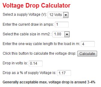
Calculated here https://www.12voltplanet.co.uk/cable-sizing-select... ( It's a very good calculator)
2 runs of the same size cable 14/0.30, 1.0mm², 8.75A - cable OD 2.6mm will do the job, loop off the tail lights to the number plate lights keeping them paired as LH and RH
You can use 5 Amp or 7.5 Amp fuses without a problem arising although I do prefer 7.5 Amp fuses as they are physically stronger
You shouldn't be using a single cable for the rear tail and number plate lights
The best way to do the job is to run 2 cables from front to rear and supply them with 2 fuses that are close to and supplied by the lighting switch, having done this you will have fused LH rear and RH rear seperately
2 x 5 Watt bulbs will draw a current of less than 1 amp, you could go real thin on the cable but it isn't good practice as it can break very easily
If you use 14/0.30, 1.0mm², 8.75A - cable OD 2.6mm https://www.autoelectricsupplies.co.uk/product/66/...
1 run of this cable over a 4 Meter length carrying a current of 1 Amp will have a volt drop of 0.14 Volts which is good, your lights will be drawing less although the length will possibly be more hence one roughly cancels out the other
Calculated here https://www.12voltplanet.co.uk/cable-sizing-select... ( It's a very good calculator)
2 runs of the same size cable 14/0.30, 1.0mm², 8.75A - cable OD 2.6mm will do the job, loop off the tail lights to the number plate lights keeping them paired as LH and RH
You can use 5 Amp or 7.5 Amp fuses without a problem arising although I do prefer 7.5 Amp fuses as they are physically stronger
GreenV8S said:
Work out the maximum current you need to carry.
Choose the maximum acceptable voltage drop. 3% is a commonly used figure - that corresponds to roughly 0.4V.
From the current and voltage you can calculate the maximum acceptable resistance via Ohms law using R = V / I.
Knowing the maximum acceptable resistance and required length you can now use the wire data sheets to choose a suitable wire.
Understand the above perfectly when used in a single resistance application. However, I've got four lights to worry about.Choose the maximum acceptable voltage drop. 3% is a commonly used figure - that corresponds to roughly 0.4V.
From the current and voltage you can calculate the maximum acceptable resistance via Ohms law using R = V / I.
Knowing the maximum acceptable resistance and required length you can now use the wire data sheets to choose a suitable wire.
I'm assuming that the process is to calculate the current using all four 5W lights so a total of 20W is applicable. Therefore the current is = 20 / 12 = 1.75A.
I can then use the resistance value for a selected cable to evaluate voltage drop at the first light.
Assuming 0.5mm2 cable then I have a resistance value of 0.0371.
The cable run to the first light is 3.5m.
Voltage drop = Current * ( Distance * 2 ) * Cable resistance
= 1.66 * ( 3.5 * 2 ) * 0.0371 = 0.416 volts (greater drop than ideal already but this is just an example process)
Does this make sense so far?
Now I've got work out the voltage drop to the next three lights ..... this is where I get proper lost!
Do I follow the same process but use the reduced current value of only three lights or something different?
Do I base the calculation on the daisy chain link length from light 1 to light 2 or something different?
Do I then repeat the process for lights 3 and 4 and adding up all the voltage drop figures to give an overall end of circuit voltage drop value?
Penelope Stopit said:
Hello
You shouldn't be using a single cable for the rear tail and number plate lights
The best way to do the job is to run 2 cables from front to rear and supply them with 2 fuses that are close to and supplied by the lighting switch, having done this you will have fused LH rear and RH rear seperately
Thanks Penelope.You shouldn't be using a single cable for the rear tail and number plate lights
The best way to do the job is to run 2 cables from front to rear and supply them with 2 fuses that are close to and supplied by the lighting switch, having done this you will have fused LH rear and RH rear seperately
I assume the logic of running 2 cables is so that a failure on one circuit only takes out half of the rear illumination and not the whole shebang?
If so, this is already a consideration that may well cause me to run two separate feeds.
At the moment I'm just trying to get the calculation logic fully sorted so that I can at least get the numbers to work.
Do you also advocate the concept of separate feeds for each brake light?
My existing loom has only a single feed for both - it uses 21W bulbs and is only 0.5mm2 cable.
12voltplanet calculator would suggest the voltage drop is a tad excessive - would you agree?
Connectors to be converted to will be the Ampseal 1.5 items rated at 14A.
Tacchino said:
Penelope Stopit said:
Hello
You shouldn't be using a single cable for the rear tail and number plate lights
The best way to do the job is to run 2 cables from front to rear and supply them with 2 fuses that are close to and supplied by the lighting switch, having done this you will have fused LH rear and RH rear seperately
Thanks Penelope.You shouldn't be using a single cable for the rear tail and number plate lights
The best way to do the job is to run 2 cables from front to rear and supply them with 2 fuses that are close to and supplied by the lighting switch, having done this you will have fused LH rear and RH rear seperately
I assume the logic of running 2 cables is so that a failure on one circuit only takes out half of the rear illumination and not the whole shebang?
If so, this is already a consideration that may well cause me to run two separate feeds.
At the moment I'm just trying to get the calculation logic fully sorted so that I can at least get the numbers to work.
Do you also advocate the concept of separate feeds for each brake light?
My existing loom has only a single feed for both - it uses 21W bulbs and is only 0.5mm2 cable.
12voltplanet calculator would suggest the voltage drop is a tad excessive - would you agree?
Connectors to be converted to will be the Ampseal 1.5 items rated at 14A.
Use the same size cable for the brake lights and loop from one side to the other, by the time a very small volt drop kicks in you will be off the pedal...lights out....7.5 Amp fuse is a must 5 Amp is too small
Must you use a plug down the rear? Why I ask is that plugs are used in many places to keep the mass production simple yet they don't do the end product any favours, you could always extend the rear loom using staggered joints with solder and heat-shrink. All the joints being together is a no goer as they can short together and the loom does get too bulky in the joints area
Edited by Penelope Stopit on Monday 10th December 13:40
Penelope Stopit said:
Yes this saves you losing all the tail lights if one fuse blows, it's best to do the same with the front side lights
Use the same size cable for the brake lights and loop from one side to the other, by the time a very small volt drop kicks in you will be off the pedal...lights out....7.5 Amp fuse is a must 5 Amp is too small
Must you use a plug down the rear? Why I ask is that plugs are used in many places to keep the mass production simple yet they don't do the end product any favours, you could always extend the rear loom using staggered joints with solder and heat-shrink. All the joints being together is a no goer as they can short together and the loom does get too bulky in the joints area
I guess you work on the assumption that the brake lights won't be on continuously.Use the same size cable for the brake lights and loop from one side to the other, by the time a very small volt drop kicks in you will be off the pedal...lights out....7.5 Amp fuse is a must 5 Amp is too small
Must you use a plug down the rear? Why I ask is that plugs are used in many places to keep the mass production simple yet they don't do the end product any favours, you could always extend the rear loom using staggered joints with solder and heat-shrink. All the joints being together is a no goer as they can short together and the loom does get too bulky in the joints area
Edited by Penelope Stopit on Monday 10th December 13:40
What happens if you're stuck on a hill with your hoof on the brake for a long period of time? Doesn't that create a risk of temperature build up in the wiring and potential further problems?
Haven't got much choice on using a connector on the rear. All the lights are mounted to the rear engine cover and that needs to be removable!
I'm going to need a pair of connectors for the rear as, even when combining everything, I've got a minimum of 7 feeds - Ampseal 1.5 series only has up to 6 pins!
Tacchino said:
Penelope Stopit said:
Yes this saves you losing all the tail lights if one fuse blows, it's best to do the same with the front side lights
Use the same size cable for the brake lights and loop from one side to the other, by the time a very small volt drop kicks in you will be off the pedal...lights out....7.5 Amp fuse is a must 5 Amp is too small
Must you use a plug down the rear? Why I ask is that plugs are used in many places to keep the mass production simple yet they don't do the end product any favours, you could always extend the rear loom using staggered joints with solder and heat-shrink. All the joints being together is a no goer as they can short together and the loom does get too bulky in the joints area
I guess you work on the assumption that the brake lights won't be on continuously.Use the same size cable for the brake lights and loop from one side to the other, by the time a very small volt drop kicks in you will be off the pedal...lights out....7.5 Amp fuse is a must 5 Amp is too small
Must you use a plug down the rear? Why I ask is that plugs are used in many places to keep the mass production simple yet they don't do the end product any favours, you could always extend the rear loom using staggered joints with solder and heat-shrink. All the joints being together is a no goer as they can short together and the loom does get too bulky in the joints area
Edited by Penelope Stopit on Monday 10th December 13:40
What happens if you're stuck on a hill with your hoof on the brake for a long period of time? Doesn't that create a risk of temperature build up in the wiring and potential further problems?
Haven't got much choice on using a connector on the rear. All the lights are mounted to the rear engine cover and that needs to be removable!
I'm going to need a pair of connectors for the rear as, even when combining everything, I've got a minimum of 7 feeds - Ampseal 1.5 series only has up to 6 pins!
Also bear in mind that these calculations are carried out using a 12 volts supply which is all well and good in theory but not in practice. When the engine is running and the alternator is charging the supply voltage is often more like 14 to 14.5 volts and the current draw will be a touch higher and there is also the temperature of the bulbs that could be taken into consideration...There is more current flowing through a cold filament than a hot one and the brake light bulbs are possibly cold most of the time if they are single filament bulbs
it goes on and on and................................
The same cable for the brake lights will do a good job but if you want to go a touch higher you could get hold of some Thin-Wall cable that is thinner than the standard cable but will handle more current. https://www.autoelectricsupplies.co.uk/product/70/... 010701 16/0.20, 0.5mm², 11.0A - cable OD 1.6mm
Penelope Stopit said:
Good question, you could keep your foot on the brake pedal and not notice any difference in the temperature of the cable, the cable is rated at 8 to 8.5 Amps, although the resistance of the cable increases as its length increases and the voltage drops to **lets say** 11 volts (doubt it will drop to this but it might), there is now 11 volts supplying 2 x 21 Watt bulbs which have a current draw of 4 Amps....No problem with the 8 Amp cable overheating
Also bear in mind that these calculations are carried out using a 12 volts supply which is all well and good in theory but not in practice. When the engine is running and the alternator is charging the supply voltage is often more like 14 to 14.5 volts and the current draw will be a touch higher and there is also the temperature of the bulbs that could be taken into consideration...There is more current flowing through a cold filament than a hot one and the brake light bulbs are possibly cold most of the time if they are single filament bulbs
it goes on and on and................................
The same cable for the brake lights will do a good job but if you want to go a touch higher you could get hold of some Thin-Wall cable that is thinner than the standard cable but will handle more current. https://www.autoelectricsupplies.co.uk/product/70/... 010701 16/0.20, 0.5mm², 11.0A - cable OD 1.6mm
I think I've just spotted a slight oops in my thinking - shoot me down in flames if I'm wrong!Also bear in mind that these calculations are carried out using a 12 volts supply which is all well and good in theory but not in practice. When the engine is running and the alternator is charging the supply voltage is often more like 14 to 14.5 volts and the current draw will be a touch higher and there is also the temperature of the bulbs that could be taken into consideration...There is more current flowing through a cold filament than a hot one and the brake light bulbs are possibly cold most of the time if they are single filament bulbs
it goes on and on and................................
The same cable for the brake lights will do a good job but if you want to go a touch higher you could get hold of some Thin-Wall cable that is thinner than the standard cable but will handle more current. https://www.autoelectricsupplies.co.uk/product/70/... 010701 16/0.20, 0.5mm², 11.0A - cable OD 1.6mm
The brake lights will be earthed independently so they will be operating as a parallel circuit. Doesn't this mean that the effective current will only half of the 1.75A of each ie. 0.875A? Unless one light goes kaput in which case the 1.75A of the remaining item is effective?
I know there are many influencing factors which, once I've understood the numerical process, I can incorporate into a spreadsheet to evaluate some "what ifs".
Undoubtedly thin wall cable is the way I'll be going.
Just worked out why you've got a good handle on these electrickery things. I had a Cerbera a few years ago and the electrics were a constant pain!
Tacchino said:
Penelope Stopit said:
Good question, you could keep your foot on the brake pedal and not notice any difference in the temperature of the cable, the cable is rated at 8 to 8.5 Amps, although the resistance of the cable increases as its length increases and the voltage drops to **lets say** 11 volts (doubt it will drop to this but it might), there is now 11 volts supplying 2 x 21 Watt bulbs which have a current draw of 4 Amps....No problem with the 8 Amp cable overheating
Also bear in mind that these calculations are carried out using a 12 volts supply which is all well and good in theory but not in practice. When the engine is running and the alternator is charging the supply voltage is often more like 14 to 14.5 volts and the current draw will be a touch higher and there is also the temperature of the bulbs that could be taken into consideration...There is more current flowing through a cold filament than a hot one and the brake light bulbs are possibly cold most of the time if they are single filament bulbs
it goes on and on and................................
The same cable for the brake lights will do a good job but if you want to go a touch higher you could get hold of some Thin-Wall cable that is thinner than the standard cable but will handle more current. https://www.autoelectricsupplies.co.uk/product/70/... 010701 16/0.20, 0.5mm², 11.0A - cable OD 1.6mm
I think I've just spotted a slight oops in my thinking - shoot me down in flames if I'm wrong!Also bear in mind that these calculations are carried out using a 12 volts supply which is all well and good in theory but not in practice. When the engine is running and the alternator is charging the supply voltage is often more like 14 to 14.5 volts and the current draw will be a touch higher and there is also the temperature of the bulbs that could be taken into consideration...There is more current flowing through a cold filament than a hot one and the brake light bulbs are possibly cold most of the time if they are single filament bulbs
it goes on and on and................................
The same cable for the brake lights will do a good job but if you want to go a touch higher you could get hold of some Thin-Wall cable that is thinner than the standard cable but will handle more current. https://www.autoelectricsupplies.co.uk/product/70/... 010701 16/0.20, 0.5mm², 11.0A - cable OD 1.6mm
The brake lights will be earthed independently so they will be operating as a parallel circuit. Doesn't this mean that the effective current will only half of the 1.75A of each ie. 0.875A? Unless one light goes kaput in which case the 1.75A of the remaining item is effective?
I know there are many influencing factors which, once I've understood the numerical process, I can incorporate into a spreadsheet to evaluate some "what ifs".
Undoubtedly thin wall cable is the way I'll be going.
Just worked out why you've got a good handle on these electrickery things. I had a Cerbera a few years ago and the electrics were a constant pain!
If you were to wire 2 x 12 volt 21 Watt bulbs in series they would illuminate at half brightness due to them having 6 volts across each of their filaments
Did I help you with a Cerbera problem? I still do post over there but it's very quiet
Tacchino said:
Now I've got work out the voltage drop to the next three lights ..... this is where I get proper lost!
Just take the maximum current in the most heavily loaded part of the cable and the length of the longest path through the cable and base your calculations on that. This will give you a figure which slightly exaggerates the total voltage drop, which is perfectly fine. You only need an approximate size, pick the next convenient cable size above that, and move on.Deciding whether you should have shared or separate fuses and whether you have enough pins on your connector capable of handling the current is far more important than trying to calculate the wire size to the nth degree.
Gassing Station | Home Mechanics | Top of Page | What's New | My Stuff