2009 mitsubushi colt 1.3 strange intermittent fault
Discussion


Penelope Stopit said:
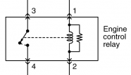
If you mean this above diagram, don't understand why the diagram should be wrong
Diagram is correct, it shows a resistor in parallel with a relay coil, the resistor is there to stop a back EMF of 100 plus volts reaching the Engine ECU relay control circuit
Many relay cases show the resistor when fitted
Here's more from 12 volt planet
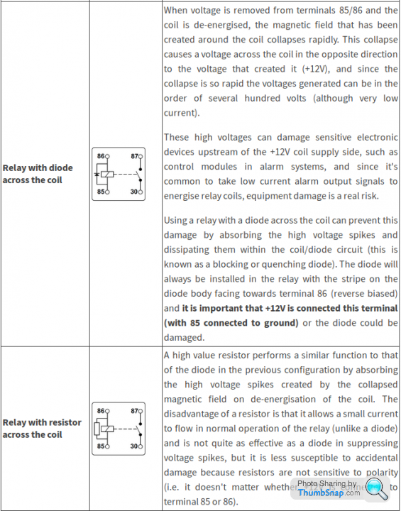
https://www.12voltplanet.co.uk/relay-guide.html
None of this has anything to do with protecting the relay contacts

The above details make sense though now you've posted that link. I can see how a high value resistor would absorb some of the high voltage due to the collapsing EMF.
It's a hole in my knowledge that has now been filled. I was taught to dump it back into the coil using a diode.
Everyday is a school day

GreenV8S said:
Penelope Stopit said:
None of this has anything to do with protecting the relay contacts
The comment may have been referring to providing a flyback circuit for the switched inductive load - which would protect the relay contacts.JustALooseScrew said:
know that
I can see how a high value resistor would absorb some of the high voltage due to the collapsing EMF.
Of the opinion that every day is a learning dayI can see how a high value resistor would absorb some of the high voltage due to the collapsing EMF.
A low value resistor will do the job and very likely quicker than a higher one yet have never carried out the test to prove this but it does add up
Problem is that a low value resistor will draw more current which would defeat the wiring in of a relay to a certain extent, depending on what was being used to control the switching
Reckon there are many here that don't post to the techie topics as they know it all inside out and it bores them to tears, it would be good if more members did post to them.....life is a learning curve and many of us enjoy learning or being corrected
Sorry,never checked back on replys!Putting correct,new relay in,the car is dead,doesn't crank at all!Short the two pins on the relay box and the car either runs perfectly,or like a bag of spanners!
I never got to the bottom of it.
The two wires that go to the ecu in the above original diagram of mine,neither show voltage with ignition on!
I never got to the bottom of it.
The two wires that go to the ecu in the above original diagram of mine,neither show voltage with ignition on!
robbocop33 said:
Sorry,never checked back on replys!Putting correct,new relay in,the car is dead,doesn't crank at all!Short the two pins on the relay box and the car either runs perfectly,or like a bag of spanners!
I never got to the bottom of it.
The two wires that go to the ecu in the above original diagram of mine,neither show voltage with ignition on!
Does seem to be an immobiliser problem but.......I never got to the bottom of it.
The two wires that go to the ecu in the above original diagram of mine,neither show voltage with ignition on!
Gassing Station | Home Mechanics | Top of Page | What's New | My Stuff