Alternator Failure, Voltage Spike. Beyond Economical Repair?
Discussion


Max_Torque said:
Penelope Stopit said:
Max_Torque said:
If the battery is connected, and it's output voltage drops to ZERO, then there is a HARD short between the positive 12v side and chassis ground! A car battery, well a decently charged one in good condition, can put out the best part of 1000 amps if shorted, and that current has to be going somewhere
There is no way anyone could apply a dead short across a good battery without noticing it, first of all there would be lots of sparks at the battery/cable terminals, welding would commence and the cables would go into meltdown if someone managed to not notice sparks flying and managed to get the cables battery terminals connected and tightened without burning their hands offApplying a short circuit across a good battery couldn't possibly drop its voltage to zero, yes the voltage would certainly drop and by how much would be governed by the size of cables with a short circuit, the voltage would then start to rise as the cables slowly burnt out
Max_Torque said:
Now, there is pretty much only one thing that can shunt 1000 amps to ground without itself immediately going POP and that is the alternator, or more precisely, the rectification diodes in the alternator. If these fail short then they will effectively clamp the +12v to chassis ground, causing the symptoms you describe
The diodes in an alternator if going short circuit will then go into meltdown and burn themselves out of the circuit or the whole rectifier pack will melt and possibly apply a dead short from alternator negative to alternator positive which would cause the alternator fuse to blow or if unfused would rapidly get to work on burning out the main alternator positive supplyA Ford Focus Alternator rectifier couldn't possibly handle 1000 Amps, the diodes would have burnt out long before reaching anything close to that much current, the cable supplying the alternator couldn't handle anything close to 1000 Amps and the internal rectifier connections would also fail long before 1000 Amps
The alternators diodes can easily "withstand" that current because they are not dropping any power, being shorted!
But yes, there would almost certainly be sparks at the terminals, but a lead on lead or lead on brass terminal is actually quite spark and "weld" resistant.
What i would expect to happen however is for the main battey "fuse" (generally a fuseable link) to blow at some point, as it should be rated to blow under exactly this condition!
You posted
Max_Torque said:
Now, there is pretty much only one thing that can shunt 1000 amps to ground without itself immediately going POP and that is the alternator, or more precisely, the rectification diodes in the alternator. If these fail short then they will effectively clamp the +12v to chassis ground, causing the symptoms you describe.
A diode that has gone short circuit is no longer a diode, it is now an electrical conductor in both directionsThere is no way that 1000 Amps can be dumped down to ground through short circuit diodes without them melting to open circuit or melting to a more substantial short circuit that would cause the rectifier soldered joints or heat welded joints to rapidly burn, melt away or melt into a blob that could create a greater short circuit, in which case the alternator positive cable would go into meltdown
You seem to be forgetting what you've posted
What's coming next.....Black is white?
Penelope Stopit said:
A diode that has gone short circuit is no longer a diode, it is now an electrical conductor in both directions
There is no way that 1000 Amps can be dumped down to ground through short circuit diodes without them melting to open circuit or melting to a more substantial short circuit that would cause the rectifier soldered joints or heat welded joints to rapidly burn, melt away or melt into a blob that could create a greater short circuit, in which case the alternator positive cable would go into meltdown
You seem to be forgetting what you've posted
What's coming next.....Black is white?
Power = Voltage X CurrentThere is no way that 1000 Amps can be dumped down to ground through short circuit diodes without them melting to open circuit or melting to a more substantial short circuit that would cause the rectifier soldered joints or heat welded joints to rapidly burn, melt away or melt into a blob that could create a greater short circuit, in which case the alternator positive cable would go into meltdown
You seem to be forgetting what you've posted
What's coming next.....Black is white?
Normal Recifier diode has a forward voltage of around 1.4 volt at high current (lets say typically 250 Amps phase current RMS for a 120A (dc output) alternator. So "In use" power is 1.4 x 200 = 350 Watts
Now lets take a shorted diode, which has a much lower voltage drop because it is shorted (lets say 1 milliohms, still some way from a "hard short" but reasonable). at 1000 Amps, that's a power loss of 1000 Watts.
So in a reasonably case, those diodes are absorbing about 3 time there normal working power, but of course, as they are shorted, we are no longer worried about their peak temperature. For a typical diode, you are going to require the junction temperature to stay below around 150 to 180 degC, otherwise that junction can fail (and the diode becomes a "not diode"). So you need to dissipate our normal 350W at 150 degC. Underbonnet coul dbe 120 degC ambient, so you'll need a Thermal impedance of less than 12 degC/Watt (and this is why alternators are cooled by fans!).
But our "shorted" diodes have already failed, they no longer care about their temperature, and the point at which something different happens is now actually the melting point of the devices, which would be > 500 degC.. Now, disspating 1000w is trivially easy, because we have another 300degC over which to drive the heat away.
Ive done plenty of specific tests for these cases, and have actually shorted car batteries (and lorry batteries...) across diodes, across coils of copper tube (filled with water as cooling) and across semiconductor devices like diodes and mosfets. And the "Current" that you can short has no real influence, because the heating is a result of the power disipated and not the current flowing!
Consider a moder MOSFET, these can handle currents of thousands of amps, despite having an active silicon area of about 1 square cm and having an active junction mass of around 2 grams! They do this because they have insanely low resistance, and so they don;t dispate much power even at massive currents......
Couple of other points:
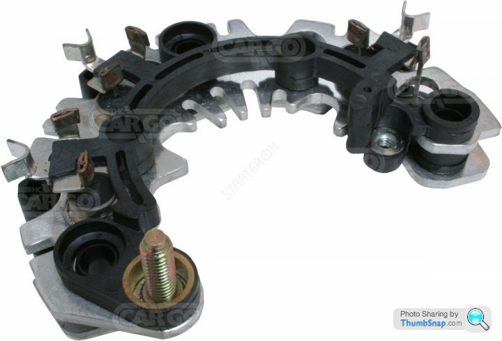
1) Alternator rectifiers are not soldered. They use sintered semiconductors in metal cans that are press fit to back plates:

When that ^^ goes dead short, it's effectively a sold bit of copper bus bar!
2) The highest resistance in the circuit following the battery itself will be the wire between the battery and the alternator. The typical 10 mm2 wire, of lets say 1.5 meters length, has a resistance of about 3 milliohms. So at 1000 Amps that wire alone will drop 3 volts, and be dissipating 3kW. But it's made of copper and it's mass is significant, as it it's surface area, so for a short period it'll manage just fine without catching on fire
Edited by anonymous-user on Saturday 19th December 16:14
Max_Torque said:
Alternator rectifiers are not soldered. They use sintered semiconductors in metal cans that are press fit to back plates:
Interesting to learn. It looks as if that rectifier pack was designed for four phase inputs. Any idea why that would be? I thought three phases was universal.
Max_Torque said:
1) Alternator rectifiers are not soldered. They use sintered semiconductors in metal cans that are press fit to back plates:
Is there any chance of you keeping this sensible? The vast majority of people that have ever seen inside an alternator know that the diodes are pressed into a plateYou surely must have given the other end of the diode a little thought
Comments posted are referring to the connections at the diodes conductor bar that your 1000 Amps is flowing through
Max_Torque said:
The highest resistance in the circuit following the battery itself will be the wire between the battery and the alternator
Will correct the above for youThe weakest link in the circuit is at the rectifier, the diode will be rated at approximately 50/60 Amps and its conductor bar a little higher
The alternator supply cable is of a far greater current carrying capacity than the diodes conductor bar and the link bar that connects to it
The short circuit diode that is now carrying 1000 Amps will act in a similar way to a fuse
GreenV8S said:
It looks as if that rectifier pack was designed for four phase inputs. Any idea why that would be? I thought three phases was universal.
The pictured rectifier is for a 3 phase stator, the stator tails are pushed through those black oval tubes and then soldered to the termination points that can be seen in the above imagePenelope Stopit said:
Is there any chance of you keeping this sensible?
I am being sensible. I have posted facts. If you don't agree with them, then that's your problem not mine!Penelope Stopit said:
The vast majority of people that have ever seen inside an alternator know that the diodes are pressed into a plate
You surely must have given the other end of the diode a little thought
Comments posted are referring to the connections at the diodes conductor bar that your 1000 Amps is flowing through
The vast majority of people have never seen inside an alternator, most people have not only no idea how they are made, but how they work either. The OP_ in this case clearly (and i'm not suggesting in any way that is abnormal or make them stupid or whatever!) is not an expert in vehicle wiring, so my posts are aimed at eductating and explaining to those interested to learn.You surely must have given the other end of the diode a little thought
Comments posted are referring to the connections at the diodes conductor bar that your 1000 Amps is flowing through
You suggest i should "think about the other end of the didoes" and then post a picture of said diodes that quite clearly shows an ultrasonic crimp, ie a mechanical, semi welded type assembly used to connect the dioodes phase input pin to the phase windings. This form of connection is used, rather than sodlering for a number of important reasons:
1) Temperature resistance; A welded (semi welded in this case) type metal to metal conect is mechanically robust across a wide range of temperatures.
2) Soldered joints required complex line techniques that are expensive to install and require careful monitoring for quality, and significant HSE requirements (hot metal, fumes, etc)
3) Sodlering has certain environmental overheads that these days are not viable (lead and fluxes etc)
4) Speed of operation. Millions of alternators are made every year, the time taken to solder the leads would be non-viable at current production volumes
For this reason, diodes are not soldered, they are unltrasonically crimped, where the crimp tool "jaws" are excited by high power ultrasonic vibrations, which actually stips the wire enamel from the phase winding before the mechicanical crimp then compacts the joint
Penelope Stopit said:
Will correct the above for you
The weakest link in the circuit is at the rectifier, the diode will be rated at approximately 50/60 Amps and its conductor bar a little higher
The alternator supply cable is of a far greater current carrying capacity than the diodes conductor bar and the link bar that connects to it
The short circuit diode that is now carrying 1000 Amps will act in a similar way to a fuse
50/60 amp rated diodes in an 120 amp (typical) rated alternator? Go luck with that one!The weakest link in the circuit is at the rectifier, the diode will be rated at approximately 50/60 Amps and its conductor bar a little higher
The alternator supply cable is of a far greater current carrying capacity than the diodes conductor bar and the link bar that connects to it
The short circuit diode that is now carrying 1000 Amps will act in a similar way to a fuse
And remember, the diode rating is for when they are FORWARD BIASED, ie current being driven from annode to Cathode, against the fowards junction voltage, ie that 1.4 volts i mentioned previsously. That 1.4 volts is why they need to be heat shinked when operating normally. (1.4 v x 100amps = 140 watts)
But when failed short, as is typcially the case after a diode has being exposed to a voltage spike exceeding it's REVERSE avalanche rating (>PIV Peak Inverse Rating), there no longer is a junction (technically the depletion zone is permanently damaged, and the annode and cathode are shorted together), as the semiconductor junction is destroyed during the avalanche event, where high electromagnetic forces pull materal from the anode and cathode and contaminate that depletion zone.
Now with a hard shorted diode, we can easily carry a huge current, because we have no (well, a very small) resistance!
It's critical to think in terms of thermal impedance here, because the current carrying capacity (the fuseing rating, the I2T the "Ampere Squared Seconds" rating) is entirely controlled by the thermal inertia and heat transfer co-efficient of that current carrying conductor.
Here is the inside of an IGBT:
You see those tin plated bond wires, they carry the entire current of the device! Yet they are tiny (around 0.4mm diameter typically) and they can only do this because they are tightly coupled to the heatsink that is the copper substrate of that device!
Same with our "diode" (well our shorted diode). It IS able to carry a huge fusing current because they are hard coupled to the internal bus bar, in fact, they are deliberately hard press fitted into that bus bar, and hard crimped to the phase windings precisely to furnish a very low thermal impedance during normal operation!
Regarding the alternator bus bar carrying less current than the cable that takes current to the battery, this is pretty clearly unlikely to be the case! For a start, most alternators use an M6 or M8 stud to connect the battery charging cable, that has a fusing factor of a LOT of amps (a quick calc with one of my fusing models, for a brass stud, suggests about 3,000 amps in free air for an M6), and the cable is necessarily reasonably long, and covered in insulation (high thermal impedance) and possibly also packed into a conduit / loom wrap etc. All of those things drop it's I2T rating enourmously. The solid copper or alluminium internal bus bar however is not insulated (other than with a protective enamel)and is thermaly reasonably coupled to the casing and the phase winding themselves (about 5kg of copper!). It also certainly has a CSA of rather more than the 10mm2 of the charging wiring to the battery.
GreenV8S said:
Max_Torque said:
Alternator rectifiers are not soldered. They use sintered semiconductors in metal cans that are press fit to back plates:
Interesting to learn. It looks as if that rectifier pack was designed for four phase inputs. Any idea why that would be? I thought three phases was universal.
Alternator are actually quite difficult to optimise because they must be rated to supply sufficient current at the lowest engine speed (normally idle, say 750 rpm engine, typically 2krpm alternator) right up to their peak speak rating (maybe 7500 rpm engine, 21krpm alternator). This requires them to be able to be wound to be able to generate enough voltage at low rotational speeds to force there rated current into the electrical system. For this reason, the typical open circuit voltage rating is around 100 to 120 volts (with a full excited rotor field)
Max_Torque said:
I am being sensible
Really? Going off on a tangent explaining to me that button diodes are pressed into a plate, when it was obvious that I was referring to the conductor bar endWhat's with you waffling on about soldered joints? Welded joints was also mentioned, I do apologise for missing out crimping
Seems that your doing what politicians do best, avoiding something by going off on a tangent
This is about 1000 Amps going to ground through a short circuit diode, have explained above how it's impossible
You comment, that you've posted the facts
Really, facts hey, can't possibly be facts if it couldn't possibly happen
Did mention earlier....what next? Black is white?
1000 Amps volts down to zero, dead short, no smoke, short circuit diode will handle it no problem........don't make me laugh
Ok then
Max_Torque said:
Now with a hard shorted diode, we can easily carry a huge current, because we have no (well, a very small) resistance!
Not a chance, the internal connections, conductor bars and links will not be able to carry 1000 Amps, the positive supply cable would also rapidly overheat, even if the supply cable was rated at 200 ampsPenelope Stopit said:
What's with you waffling on about soldered joints?
er, you said (my bold)Penelope Stopit said:
The pictured rectifier is for a 3 phase stator, the stator tails are pushed through those black oval tubes and then soldered to the termination points that can be seen in the above image
Penelope Stopit said:
Seems that your doing what politicians do best, avoiding something by going off on a tangent
I'm not avoiding anything. I am explaining why a relatively small cross section conductor can carry what appears to be a reasonably high current.Penelope Stopit said:
This is about 1000 Amps going to ground through a short circuit diode, have explained above how it's impossible
Impossible is a strong word ;-)I have explained how a typical alternator when failed hard short could indeed pull a typical car battery to close to zero volts, and do so for a short period (probably until the primary battery fuse blows, ie for something like 3 seconds)
Penelope Stopit said:
the positive supply cable would also rapidly overheat, even if the supply cable was rated at 200 amps
1000 amps, through a 10mm^2 cable:Cable specific resistance: 1.91 KOhm/Km
Cable Length: 1.5m
Therefore:
Cable Power loss: 2865 watts (1000A through 2.865 milliohm)
Density of copper: 8960 Kg/m^3
Specific heat of copper: 385 J/Kg.K
Mass of copper in cable: 0.135 Kg (1.5m of 10^2mm = 15,000 mm^3)
Heating factor (under adiabatic conditiions) 51.7 J/degC
Assuming start temperature of 50 degCm end temp of 300 degC (typical automotive spec cable insulation starts to melt at around 300degC)
Requires 12,936 joules (250degC at 51.7 Joules per degC)
So that's 4.52 seconds to heat a 10mm^2 cable to the point where the insulation may start to melt, but assumes ZERO heat loss to ambient, which is of course unrealistic under that sort of time period. Actual time period likely to be around 6 seconds as an estimate.
So basically, if the main battery fuse tsakes less time to go POP than 6 seconds, the alternator cable will not show obvious signs of thermal damage
And i can assure you that the main battery fuse will be EXPRESSELY designed to do just that, to protect that cable from a full thermal event......
We are also assuming the battery in question can actually supply a full 1000 amps. IME, that is unlikely for a typical passenger car sized battery. Ive measured short circuit currents in the region of up to 800 amps more typically, and they only occur for a couple of seconds as the battery has insufficient charge mobility (ie it's internal resistance climbs rapidly at those sorts of discharge rates)
Max_Torque said:
Penelope Stopit said:
What's with you waffling on about soldered joints?
er, you said (my bold)Penelope Stopit said:
The pictured rectifier is for a 3 phase stator, the stator tails are pushed through those black oval tubes and then soldered to the termination points that can be seen in the above image
You've lost me, the stator leads are soldered to the rectifierMax_Torque said:
We are also assuming the battery in question can actually supply a full 1000 amps
We????I'm not assuming anything of the sort
Have already commented that the new battery is very likely flat or faulty
What I've assumed is that the battery was left connected while testing was being carried out, the OP did mention the battery being connected
If the battery lead was touched to the battery terminal rather than being connected there would be little harm done but a massive arcing couldn't have been missed, yet there is no mention of arcing
One thing leads to another as PH topics do and there is a discussion about a 1000 Amp current draw through an alternator diode
Yet now it seems that your 1000 Amps has had 200 Amps vanish from it which leaves you with 800 Amps, the circuit is fused and that it will blow in 3 or 6 seconds (pretty sure you mention both figures)
Earlier you commented - And because a wet lead acid battery is about 20 kg of material, it can withstand that power dissipation for a significant period of time
Am now wondering if you class 3 to 6 seconds as a significant amount of time, I don't
Anyway, It's a fact that there is no way the internal links of a rectifier will withstand 1000 Amps for a significant amount of time and going by the size of the button diode post it would very likely glow and blow in a short time
There is no mention of an alternator fuse blowing, simply a loss of volts
Flat or faulty battery it is then
Max_Torque said:
There are two sets of 3 phase connections to the stator (phase) windings. Each is an "end" of each of the stators 3 phase windings.
Yes, I'm looking at the three pairs of diodes pressed into the two plates, corresponding to the three windings. There are what look to me like unpopulated holes for a fourth pair of diodes.Thank you for all the replies and suggestions. The car is being recovered back to my parents' house tomorrow, with it being so close to Christmas it'll probably be early January before I'll be able to get someone out to take a look at it. For now, the plan is still to get an auto electrician to take a look at it. Although,
Mods - can we move this back to General Gassing, please? The intention of the thread was not to discuss the intricacies and workings of an alternator (though I am grateful for the discussion and education), it was to garner the experience of the PH community of similar issues, cost of rectification and if it was worth pursuing a fix based on the feedback. I don't think I'll get that feedback with this in Home Mechanics.
Thanks again all who have contributed.
Max_Torque said:
...
Again i cannot stress enough the importance of not doing this with the car's battery supplying power, as it is powerful enough to cause endless further problems if shorted across electrical / electronic items! The alternator going short has SAVED these other items, please don't now blow them all up by reconnecting the battery willy-nilly!!!
I fear the initial diagnosis of a dead battery lead to a new one bought and fitted and when that didn't work it went off to the main dealer for diagnosis. From their report it sounds like they've reconnected the battery to do further testing. Perhaps further damage has been done since the original incident meaning it may be too late for this Focus.Again i cannot stress enough the importance of not doing this with the car's battery supplying power, as it is powerful enough to cause endless further problems if shorted across electrical / electronic items! The alternator going short has SAVED these other items, please don't now blow them all up by reconnecting the battery willy-nilly!!!
Max_Torque said:
...
The vast majority of people have never seen inside an alternator, most people have not only no idea how they are made, but how they work either. The OP_ in this case clearly (and i'm not suggesting in any way that is abnormal or make them stupid or whatever!) is not an expert in vehicle wiring, so my posts are aimed at eductating and explaining to those interested to learn.
...
100% correct. The discussion has been interesting, the workings of an alternator is not something I've ever considered before!The vast majority of people have never seen inside an alternator, most people have not only no idea how they are made, but how they work either. The OP_ in this case clearly (and i'm not suggesting in any way that is abnormal or make them stupid or whatever!) is not an expert in vehicle wiring, so my posts are aimed at eductating and explaining to those interested to learn.
...
BUG4LIFE said:
I currently have a dead alternator in my Jaguar STR.
...
I guess you'd have the same options OP. Would a used item not be a good option considering the worth of the car?
Yes, more than likely it will be a used item. A few here have mentioned using a refurb item with no issues so given the value of the car that is the sensible option. I hope you get your car fixed soon, I'm sure I recently read a Readers Cars thread about someone newly acquiring a Jaguar STR - is that yours?...
I guess you'd have the same options OP. Would a used item not be a good option considering the worth of the car?
Mods - can we move this back to General Gassing, please? The intention of the thread was not to discuss the intricacies and workings of an alternator (though I am grateful for the discussion and education), it was to garner the experience of the PH community of similar issues, cost of rectification and if it was worth pursuing a fix based on the feedback. I don't think I'll get that feedback with this in Home Mechanics.
Thanks again all who have contributed.
JohnWest said:
Thank you for all the replies and suggestions. The car is being recovered back to my parents' house tomorrow, with it being so close to Christmas it'll probably be early January before I'll be able to get someone out to take a look at it. For now, the plan is still to get an auto electrician to take a look at it
Good ideaJohnWest said:
it was to garner the experience of the PH community of similar issues, cost of rectification
It's impossible to cost a diagnosis and repairJohnWest said:
I don't think I'll get that feedback with this in Home Mechanics
A touch harsh, many have posted their thoughts and suggestionsSomething to bear in mind, if the replacement battery is faulty it needs replacing sooner rather than later. Leaving a battery stood inactive may void its warranty, it all depends on how good the customer service is at place of purchase
Penelope Stopit said:
A touch harsh, many have posted their thoughts and suggestions
Something to bear in mind, if the replacement battery is faulty it needs replacing sooner rather than later. Leaving a battery stood inactive may void its warranty, it all depends on how good the customer service is at place of purchase
The comment on not getting the feedback was based on the replies received while the thread was in GG which (I assume) gets far more traffic than this part of the forum, simply as it contains a broader range of topics. I'm happy to be proven wrong though.Something to bear in mind, if the replacement battery is faulty it needs replacing sooner rather than later. Leaving a battery stood inactive may void its warranty, it all depends on how good the customer service is at place of purchase
Point noted regarding the new battery. I'll borrow a multimeter to test it, if dead then I'll take it back.
Gassing Station | Home Mechanics | Top of Page | What's New | My Stuff