Wheel spacers, who has fitted them? before and after pics?
Discussion


C.A.R. said:
I've had spacers - albeit genuine OZ racing ones which took their Superleggera wheel from Ford offset down to Peugeot offset, therefore maintaining the same geometry albeit with a slightly wider tyre. They looked frightning because they were 26mm thick though!
Thats a Chop Shop style spacer !lostkiwi said:
With bolt through spacers the original stretch design spec is no longer valid as the bolt is now longer hence can deform more along its length. This results in less compressive force being applied to the mating surfaces hence adding more stress to the bolts. Coupled to the extra stress added to the bolts as a result of the leverage effect of moving the wheel outwards off the hub it can seriously stress the bolts.
I'm a bit late to this, but this doesn't sound quite right to me...It's saying that a longer bolt will stretch more than a shorter bolt, for the same torque, and hence apply less clamping force.
I'm pretty sure that the clamping force is the same irrespective of the length of the bolt. None of the formulas I can find include length, just the diameter and the torque applied.
In which case the above paragraph is wrong, and no extra stress is applied to the bolts. The bits about extra stress on bearings etc will still apply of course.
CrutyRammers said:
lostkiwi said:
With bolt through spacers the original stretch design spec is no longer valid as the bolt is now longer hence can deform more along its length. This results in less compressive force being applied to the mating surfaces hence adding more stress to the bolts. Coupled to the extra stress added to the bolts as a result of the leverage effect of moving the wheel outwards off the hub it can seriously stress the bolts.
I'm a bit late to this, but this doesn't sound quite right to me...It's saying that a longer bolt will stretch more than a shorter bolt, for the same torque, and hence apply less clamping force.
I'm pretty sure that the clamping force is the same irrespective of the length of the bolt. None of the formulas I can find include length, just the diameter and the torque applied.
In which case the above paragraph is wrong, and no extra stress is applied to the bolts. The bits about extra stress on bearings etc will still apply of course.
dl = F L / E A (1)
where
dl = change in length of bolt (inches, mm)
F = applied tensile load (lb, kN)
L = effective length of bolt where tensile strength is applied (inches, mm)
E = Young's Modulus of Elasticity (psi, N/mm2)
A = tensile stress area of the bolt (square inches, mm2)
The tensile stress area can be expressed as
A = 0.7854 (d - 0.9743 / n)2 (2)
where
d = nominal diameter of bolt (inches, mm)
n = number of threads per inch (pitch)
From that the longer the bolt the more it will stretch for a given force all other things being equal. If we increase the tension forces on the bolt the longer bolt will stretch more. If we were to graph what happens when we have a static clamping force of say 1000kgs and then add another 500kgs tension force to the bolt (through forcing the hub away from the spacer for example) the longer bolt will stretch more reducing the clamping force at the hub/spacer/interface even though the tensile force on the bolt is the same for both.
As the bolt passes through hub/spacer/wheel interfaces it creates a point of potential relative shearing movement.
If this is the interface between a spacer of say 25mm then we introduce two places of potential movement. The first is the interface at the hub between hub and spacer and the second is the interface between spacer and wheel. We don't want any shearing forces at either of these points (as can happen if the hub slips against the spacer for example).
When we have an interface such as hub to spacer we also introduce a leverage effect where the centre of force through the wheel is now further out from the hub face. The weight of the vehicle will therefore apply an amount of force longitudinally along the bolt when it is at the bottom. Its not a huge force but its still there. Add braking, cornering, steering and bump forces and we add more stresses. If those stresses reduce the clamping forces at the hub (i.e. the hub to spacer friction) we risk introducing a rotational element of force that appears at the bolt as a shearing force, which are to be avoided at all costs.
All rotational forces should be through the friction between hub and spacer and wheel. No rotational forces should be borne by the bolts. Their sole function is to clamp the faces together with enough force to prevent slippage.
This is what I was trying to say (though probably not very clearly and possibly still not clearly).
lostkiwi said:
Bolt stretching according Hook's Law can be expressed as
dl = F L / E A (1)
where
dl = change in length of bolt (inches, mm)
F = applied tensile load (lb, kN)
L = effective length of bolt where tensile strength is applied (inches, mm)
E = Young's Modulus of Elasticity (psi, N/mm2)
A = tensile stress area of the bolt (square inches, mm2)
The tensile stress area can be expressed as
A = 0.7854 (d - 0.9743 / n)2 (2)
where
d = nominal diameter of bolt (inches, mm)
n = number of threads per inch (pitch)
From that the longer the bolt the more it will stretch for a given force all other things being equal. If we increase the tension forces on the bolt the longer bolt will stretch more. If we were to graph what happens when we have a static clamping force of say 1000kgs and then add another 500kgs tension force to the bolt (through forcing the hub away from the spacer for example) the longer bolt will stretch more reducing the clamping force at the hub/spacer/interface even though the tensile force on the bolt is the same for both.
As the bolt passes through hub/spacer/wheel interfaces it creates a point of potential relative shearing movement.
If this is the interface between a spacer of say 25mm then we introduce two places of potential movement. The first is the interface at the hub between hub and spacer and the second is the interface between spacer and wheel. We don't want any shearing forces at either of these points (as can happen if the hub slips against the spacer for example).
When we have an interface such as hub to spacer we also introduce a leverage effect where the centre of force through the wheel is now further out from the hub face. The weight of the vehicle will therefore apply an amount of force longitudinally along the bolt when it is at the bottom. Its not a huge force but its still there. Add braking, cornering, steering and bump forces and we add more stresses. If those stresses reduce the clamping forces at the hub (i.e. the hub to spacer friction) we risk introducing a rotational element of force that appears at the bolt as a shearing force, which are to be avoided at all costs.
All rotational forces should be through the friction between hub and spacer and wheel. No rotational forces should be borne by the bolts. Their sole function is to clamp the faces together with enough force to prevent slippage.
This is what I was trying to say (though probably not very clearly and possibly still not clearly).
No, that's very clear indeed, thanks for taking the time dl = F L / E A (1)
where
dl = change in length of bolt (inches, mm)
F = applied tensile load (lb, kN)
L = effective length of bolt where tensile strength is applied (inches, mm)
E = Young's Modulus of Elasticity (psi, N/mm2)
A = tensile stress area of the bolt (square inches, mm2)
The tensile stress area can be expressed as
A = 0.7854 (d - 0.9743 / n)2 (2)
where
d = nominal diameter of bolt (inches, mm)
n = number of threads per inch (pitch)
From that the longer the bolt the more it will stretch for a given force all other things being equal. If we increase the tension forces on the bolt the longer bolt will stretch more. If we were to graph what happens when we have a static clamping force of say 1000kgs and then add another 500kgs tension force to the bolt (through forcing the hub away from the spacer for example) the longer bolt will stretch more reducing the clamping force at the hub/spacer/interface even though the tensile force on the bolt is the same for both.
As the bolt passes through hub/spacer/wheel interfaces it creates a point of potential relative shearing movement.
If this is the interface between a spacer of say 25mm then we introduce two places of potential movement. The first is the interface at the hub between hub and spacer and the second is the interface between spacer and wheel. We don't want any shearing forces at either of these points (as can happen if the hub slips against the spacer for example).
When we have an interface such as hub to spacer we also introduce a leverage effect where the centre of force through the wheel is now further out from the hub face. The weight of the vehicle will therefore apply an amount of force longitudinally along the bolt when it is at the bottom. Its not a huge force but its still there. Add braking, cornering, steering and bump forces and we add more stresses. If those stresses reduce the clamping forces at the hub (i.e. the hub to spacer friction) we risk introducing a rotational element of force that appears at the bolt as a shearing force, which are to be avoided at all costs.
All rotational forces should be through the friction between hub and spacer and wheel. No rotational forces should be borne by the bolts. Their sole function is to clamp the faces together with enough force to prevent slippage.
This is what I was trying to say (though probably not very clearly and possibly still not clearly).
 All that makes perfect sense.
So the longer bolt applies the same clamping force in a static situation, but is more prone to outside forces causing it to stretch and hence momentarily reducing the clamping force. (Which could then give rise to slip and sheer and all that bad stuff).
So (as usual with engineering), it's just a question of whether the longer bolts have enough margin in them that all that bad stuff won't happen.
(The reason I'm interested is because I've got 25mm spacers on my kit car, to bring the wheels into the correct alignment. The approved solution is to buy custom two piece wheels to get the right offset, but I didn't really like them, and lots of people run other wheels with spacers, instead.)
I use 15mm hubcentrics on the front of my track car purely so that the wheels clear the brake calipers. I understand it's pretty common on track/race cars to use spacers for things such as brake clearance or spring platform clearance on coilovers. I've not had any issues as yet, touch wood!

motorhole said:
I use 15mm hubcentrics on the front of my track car purely so that the wheels clear the brake calipers. I understand it's pretty common on track/race cars to use spacers for things such as brake clearance or spring platform clearance on coilovers. I've not had any issues as yet, touch wood!
I run 15mm H&R spacers up front on my road car to clear my brakes also, I found it made the car very twitchy. I balanced it all out with 20mm H&R trak+ fitted the rear .How do you find yours handles with just the fronts fitted ?
robinessex said:
triggerh4ppy said:
Riley Blue said:
One car in the pics above would appear to have those fitted...
im confused, surely this will attach to the wheel hub, how will this give you camber. it will just give you incredibly wobbly wheels. or is that meant to be a joke?PapaJohns said:
I run 15mm H&R spacers up front on my road car to clear my brakes also, I found it made the car very twitchy. I balanced it all out with 20mm H&R trak+ fitted the rear .
How do you find yours handles with just the fronts fitted ?
My car's a bit of a mongrel of various BMWs from over the years, so as it happens, with the front spacers fitted the rear track is only 2 mm per side narrower than front and it seems to handle fine How do you find yours handles with just the fronts fitted ?
SHutchinson said:
DS197 said:
yonex said:
The idea of spending money on something to add unsprung weight, and in the case of the cheap ones, risk poor machining and plating screwing up your wheel balance is baffling to me. Unless they are manufacturers ones I wouldn't bother.
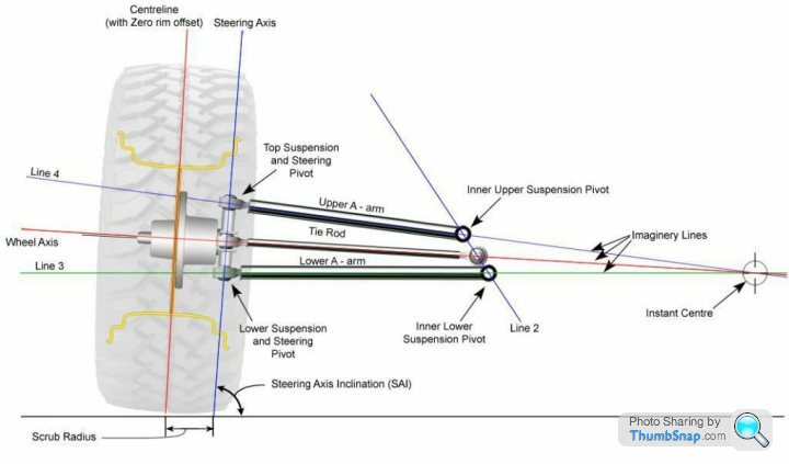
They're mostly used for looks, not performance. Unless they're fitted to increase the track.You put different rims on - same width, but with 0mm offset, and 25mm spacers. The centreline of the wheel is exactly where it was. The track is the same. The centre of loading passes through the centre of the wheel bearing again, so the loading and the geometry remains the same.
Simply increasing the track MIGHT increase lateral stability - but the effects on the geometry, especially of the steering, could prove counter-productive.

J4CKO said:
Thats a Chop Shop style spacer !
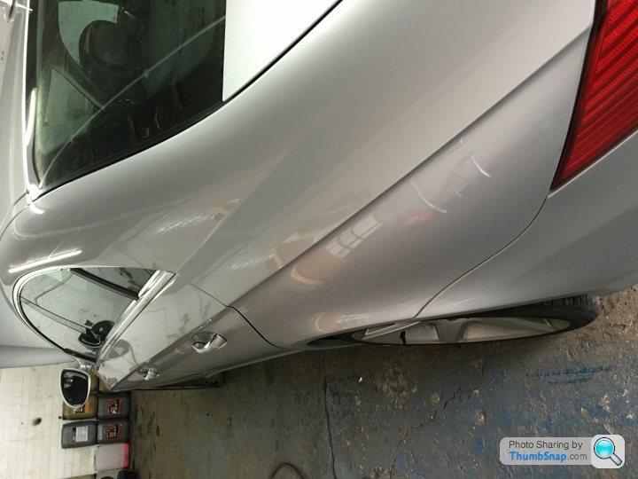
They were massive to look at; here is the best picture I can find -
You can just about see the spacer between the back of the wheel and the hub. To fit, they had to 'locate' into the back of the wheels with a spring clip and felt very solid. The wheel bolts went all the way through these, which did mean finding somme really long wheel bolts...

Gassing Station | General Gassing | Top of Page | What's New | My Stuff