Vixen 302 V8 Tweety
Discussion


Thanx Moto, best compliment ever! ;-) We should use our cars to bring a smile on our faces, that's the bottom line for me!
Regarding mass, interesting topic, would love to hear more from others. My info (measured on 4 scales)is:
TVR Vixen S2 with xflow and dual webers, 780 kg wet
TVR Vixen S2 (same car, after engine swap) with Vauxhall Redtop and type 9, 790.5 kg wet (FL 189, FR 212, RL 194, RR 195.5)
TVR Vixen S2 (car from this topic) with Ford V8 302, wet, s/s chassis, viper diff 893.5 kg.
I would say on the negative side compared to an original Griff/Tuscan V8 are the heavier wheel/tire combo, the beefier suspension, the roll bar, diff and the chassis mods. On the positive side are the lighter battery, alternator, the alloy cylinder heads, not a lot of interior trim, alloy gearbox casing.
'Wet' means in my measurements with all coolant, oils and approx. 20 liters of fuel.
The Ford V8 with alloy heads is actually quite light.
I would guess all in all it would be approx. the same mass as an old Tuscan v8, but would love to see measured values.
I think literature states 730 kg for a Vixen S2, and 865 kg (1907 lbs) for a Tuscan V8. I guess it's dry.
I would estimate most on the road TVR V8 oldies are in the 900-1000kg range, but would love from people out there.
Edited by ephemera on Tuesday 18th August 14:41
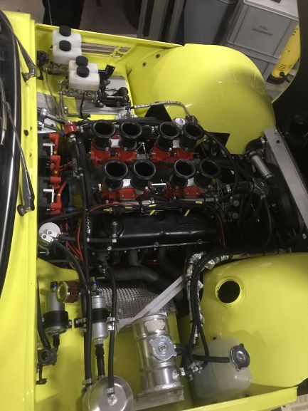
A small update: the past months I finished installing the eight individual throttle bodies to Tweety, the Ford 302 V8 engined Vixen S2.
A Kronenburg KMS ECU controls the spark and injection.
Installation included a.o. fitting a trigger wheel, BDP sensor, extra wiring loom, DIS-coils with custom ignition leads and new spark plugs, new throttle linkage, water and air temperature sensors, throttle position sensor, lambda sensors, large injectors, high pressure fuel pump and filter, special intake manifold, VGS throttle bodies and long intake trumpets.
Tweety was set up on the chassis dyno at KMS, and the first mapping returned a car which was completely transformed compared to the time the Edelbrock carburettor was installed. Very responsive and eager, even angry. It is tremendous fun. We could not do a full power run this time, a.o. due to time constraints and too much slip on the rollers without strapping it down to increase pressure on the back of the car. But already an easy 320 Nm at 1400 rpm and 410 Nm at 3400 rpm means I am a very happy bunny. I estimate it will have somewhere between 300 and 400 hp in the end.
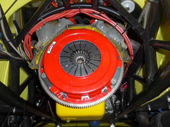
The standard Mustang clutch starting slipping soon afterwards, so it has now been replaced with a heavy duty larger diameter McLeod clutch, which is holding up fine.
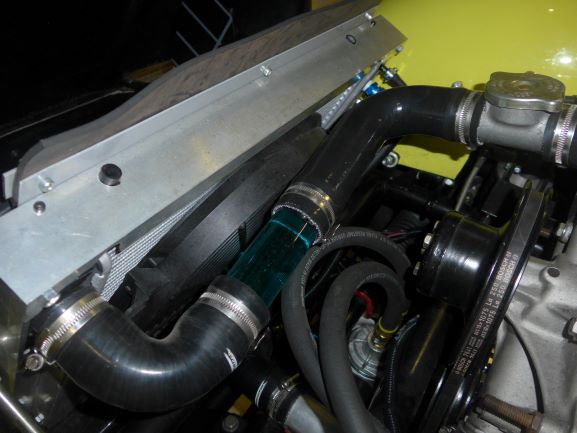
A special transparent high quality glass tube is now also installed in the cooling circuit, so now you are actually able to see the coolant flow.
Today was the day the first real road test was done in this final configuration of Tweety, and it is simply a blast!
A Kronenburg KMS ECU controls the spark and injection.
Installation included a.o. fitting a trigger wheel, BDP sensor, extra wiring loom, DIS-coils with custom ignition leads and new spark plugs, new throttle linkage, water and air temperature sensors, throttle position sensor, lambda sensors, large injectors, high pressure fuel pump and filter, special intake manifold, VGS throttle bodies and long intake trumpets.
Tweety was set up on the chassis dyno at KMS, and the first mapping returned a car which was completely transformed compared to the time the Edelbrock carburettor was installed. Very responsive and eager, even angry. It is tremendous fun. We could not do a full power run this time, a.o. due to time constraints and too much slip on the rollers without strapping it down to increase pressure on the back of the car. But already an easy 320 Nm at 1400 rpm and 410 Nm at 3400 rpm means I am a very happy bunny. I estimate it will have somewhere between 300 and 400 hp in the end.
The standard Mustang clutch starting slipping soon afterwards, so it has now been replaced with a heavy duty larger diameter McLeod clutch, which is holding up fine.
A special transparent high quality glass tube is now also installed in the cooling circuit, so now you are actually able to see the coolant flow.
Today was the day the first real road test was done in this final configuration of Tweety, and it is simply a blast!
Edited by ephemera on Monday 24th September 20:38


Now Tweety has become an Angry Bird.... here two short videos with some sounds:
https://vimeo.com/293519683
https://vimeo.com/293519709
https://vimeo.com/293519683
https://vimeo.com/293519709
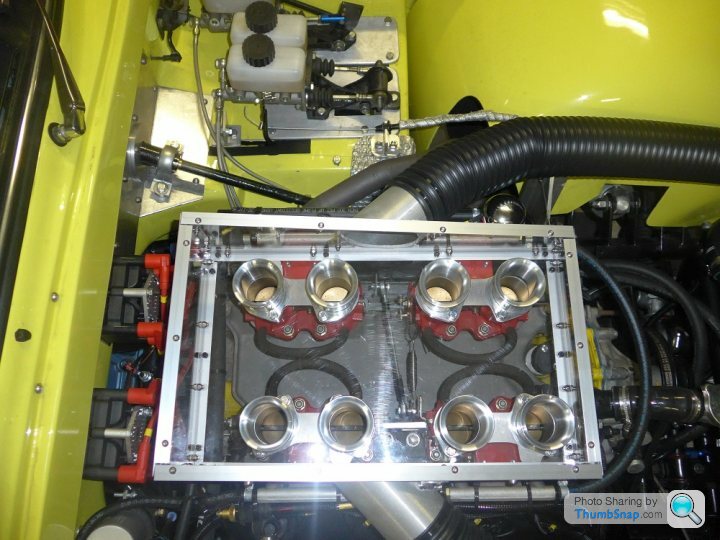
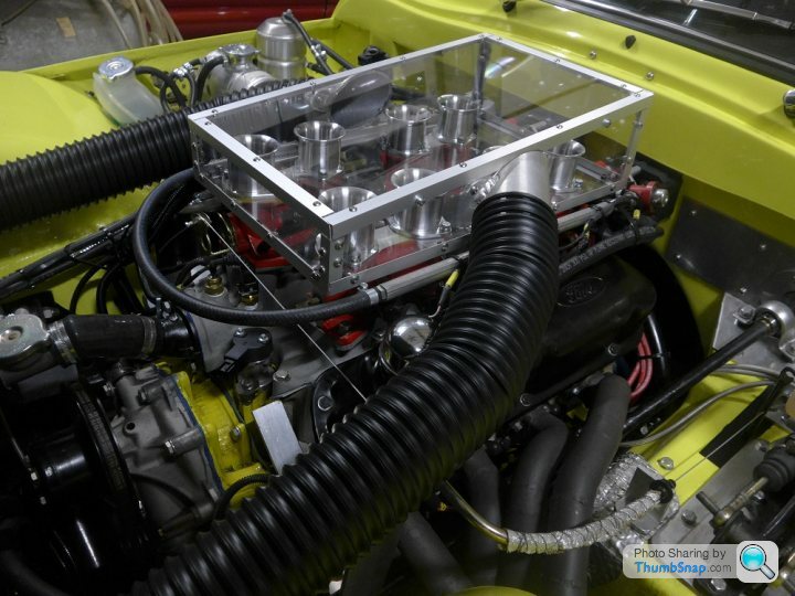
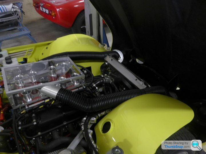
Last week working on a polycarbonate ('Lexan', so clear) airbox experiment. I am now using shorter trumpets than the original set to ensure enough clearance above the bell mouths. Next month the fine tuning on the chassis dyno is planned, maybe I can do a comparison between the different options. The airbox is receiving cold and filtered air from the two sides of the nose, near the indicators. Technically a better option than hot and unfiltered air from the engine compartment of course. I didn't want to use trumpet filters, socks or foam filters, but I also wanted still to be able to see the ITB's, so let's see if this works. Yes it's square, not too big and no flow calculations have been done, but on the other hand, I haven't really seen a fully transparent airbox before. If it doesn't work properly, I will go to plan B. 
Edited by ephemera on Saturday 20th October 01:30
Edited by ephemera on Saturday 20th October 01:45

Hi Neil, interesting thoughts, thank you!
I considered using the leading edge bonnet vents for intake purposes, but I decided having maximum heat release when entering low speed heavy traffic is more important in my road application. Also filtering that air is difficult due to the space constraint. Last reason was that I don't like to have an air connection between the fixed location airbox and a bonnet which can open, it will be very hard to seal properly. The air coming from the front of the car is luckily also dense in that area, and allows me to use two large air filters behind the indicator area which can be fixed to the chassis, so stable and independent from an opening bonnet.
Could you elaborate why the airbox should not be fully sealed in your opinion? I would think that is precisely the purpose of it? Making sure only cool and filtered air comes in the engine? Possible back fires are hopefully taken care of by the two air intakes.
Opening the airbox upper side and sealing it with a rubber seal against the bonnet would be difficult for me to achieve, there is a relative movement between the two, and wear particles from rubber and bonnet inner surface should not be allowed in the engine. The extra volume created is minimal, the airbox is a few mm from the bonnet as it is.
But I am always willing to learn, so any thoughts are very appreciated!
The race car solution is to have a hole in the top of the bonnet, minimal filtration and a seal along an open side airbox. I don't know how they cope with rain, though ;-)
But proof and pudding, testing and measuring etc ;-) Will keep you all posted.
Edited by ephemera on Saturday 20th October 15:22

Bernard, thanks for the interesting points you raised, in this way a thread like this is getting greater and greater for people doing these kind of things.
Heat release: good point, I tried to keep the length of the airbox limited so the air vents are still as open as possible. My train of thought was that in heavy traffic the hot air will ascend to the highest point under the bonnet and if there are holes at that location it will find its way out. It will be way better than nothing, and also better than gulping that hot air into the engine again. But I will test and report back!
By the way, in the latest Practical Performance car magazine Dave Walker of Emerald wrote an article stating 10 degr intake temperature difference equals around 3% power difference. I think our under bonnet temperatures can easily reach 50 degr and beyond, compared to say 20 degr outside. Of course you need to insulate your air supply to profit from that, but that is an additional advantage of polycarbonate compared to say aluminium.
The full radius bell mouth shape you mentioned: yes, this is correct. I have at the moment an intermediate radius shape for the short trumpets, and a three quarter radius for the long trumpets. But good shout, I will try to borrow full radius trumpets on the dyno day and compare. Place your bets1 I think the (lack of) free area above and around the mouths will play a significant role.
Intake cross section air hoses/filters: I have two hoses with 75mm internal diameter, so total cross section of 8831 mm^2. As you said, a single throttle body plus intake hose of say an LS is 85 mm or smaller, so 5672 mm^2. Also, when one looks at the intake hoses of a nineties Griffith 500, a V8 Cerbera and the 2020 Griffith, I am not too concerned in that area.
In the end, life is full of compromises, hot/cold air inlet temperatures, withstand heavy traffic real life conditions, filtering air for engine protection, trumpet length for torque/power compromises, looks (let's be honest), costs, etc... but I love to test and conclude based on science and hard data. All remarks are welcome during the journey though ;-)
I would love to make an actuated continuously variable length trumpet system one day, but the downdrafts on this project don't have the space for that.
www.turbosport.co.uk/showthread.php?t=455891
Dyno update, with video's:
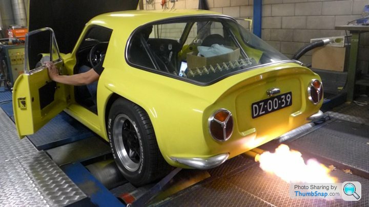
The chassis dyno days the past week were interesting. To cut a long story short, The inlet manifold was a ported one (48 mm ports), the linkage system was not really suitable for very fine adjustment, so I decided to bite the bullet and remove the current 45mm VGS ITB set up and replace it with a 50mm KMS set up with new throttle and synchronization linkage system. The car was strapped down this time and the only problem was a slight oil leak from the oil dipstick tube where it was pushed into the engine block, need to address that. But fortunately we could do some dyno runs and in the end I am very happy, the driveability is beyond expectations, and the performance very healthy. Here are some video's and photos:
https://vimeo.com/299525289
https://vimeo.com/299525901
Edited by ephemera on Wednesday 7th November 22:02
Gassing Station | TVR Classics | Top of Page | What's New | My Stuff