Peugeot 205 Saloon Libre - RWD Space-Frame Silhouette Racer
Discussion


Trtj said:
That spaceframe looks colossal. Any idea of the weight of the frame alone? You're using catia so i expect an answer to say hmmm 3dp!
The space-frame and sills weigh 122.914kg. 
I want it to come in under 600kg with driver.. currently it's at 499kg with me, excluding bodywork, exhaust system, cooling, fuel and electrical systems, and floor / bulkheads & aero. Squeezing that all in to 100kg will be a pretty tall order!
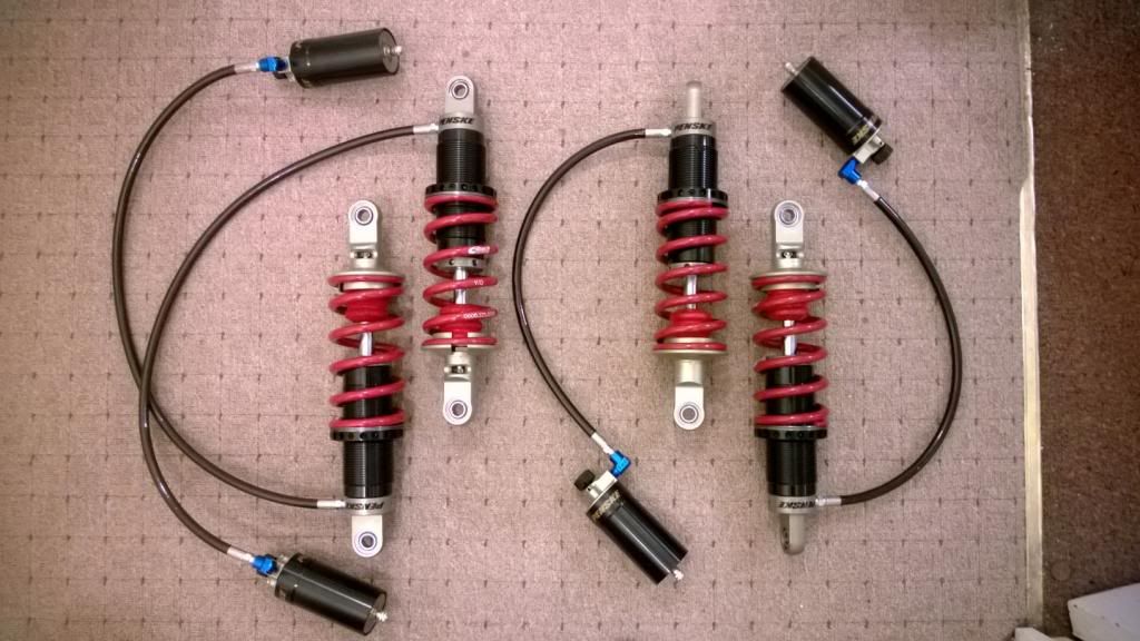
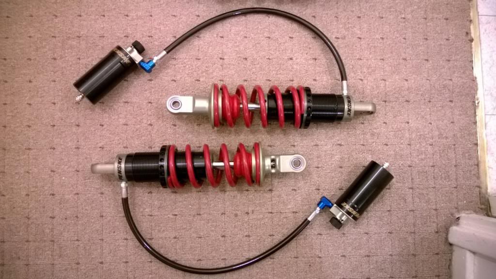
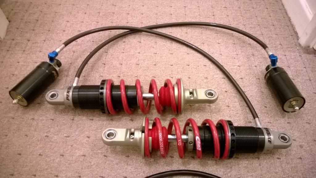
Phil - They're 2-way adjustable. I figured I'll have enough variables to tune to warrant not spending an extra 1.5k on low speed compression! I can always upgrade the internals later.

Max_Torque said:
Well, that's gonna slow you down a bit ;-)
I did look at going to a partial spaceframe for my Ibiza, but when you look at how well optimised the original monocoque actually is, there is was precious little advantage. However, if you can lower the overall vehicle height, add low level aero, and clothe it in super lightweight body panels then for a race car it makes much more sense!
(and in the back of my mind was the fact that rally cars can hit really quite substantial objects on occasions, and i'd rather sacrifice the shell than me!)
Also, for a rally car, basic "low speed" mechanical traction is important (hence my gearbox being at the back of the car over the drive wheels) whereas a circuit car can use super low ride heights and aero tricks to get good traction (and they don't spend a lot of time in 1st and 2nd gear ;-)
Yeah the weight saving of a space-frame really isn't that much over a monocoque with a decent roll cage, at least not for saloon cars. The big advantages start coming in the freedom you get over layout and locating certain parts, and that you can design for low weight & CoG height right from the start. I'm sure I don't need to tell you this, it's more for other readers!I did look at going to a partial spaceframe for my Ibiza, but when you look at how well optimised the original monocoque actually is, there is was precious little advantage. However, if you can lower the overall vehicle height, add low level aero, and clothe it in super lightweight body panels then for a race car it makes much more sense!
(and in the back of my mind was the fact that rally cars can hit really quite substantial objects on occasions, and i'd rather sacrifice the shell than me!)
Also, for a rally car, basic "low speed" mechanical traction is important (hence my gearbox being at the back of the car over the drive wheels) whereas a circuit car can use super low ride heights and aero tricks to get good traction (and they don't spend a lot of time in 1st and 2nd gear ;-)
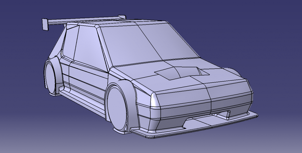
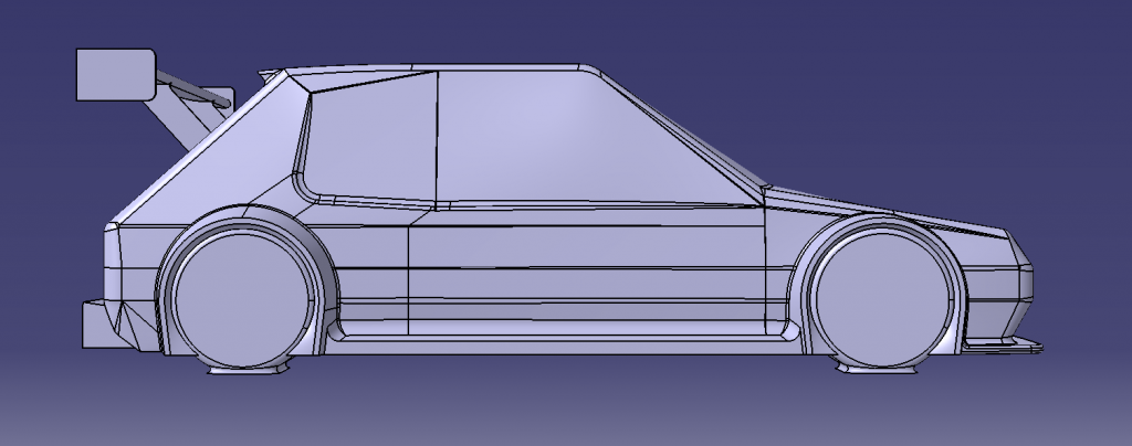
For those interested in what it'll look like, this is where my CFD has got me so far:
You wouldn't believe the difference that little roof spoiler makes!

Wow, really? I'll have to check that out!
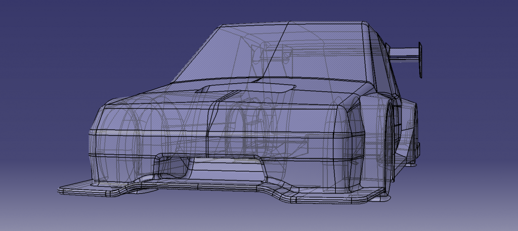
I've been hiding inside due to the holidays and s t weather, so nothing has progressed on the build.. but I have been doing lots of CFD work trying to sort the bodywork & aero out. Here's how things look at the moment:
205 6R4
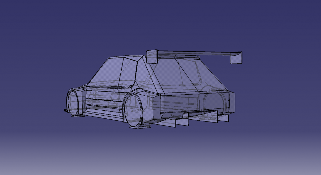
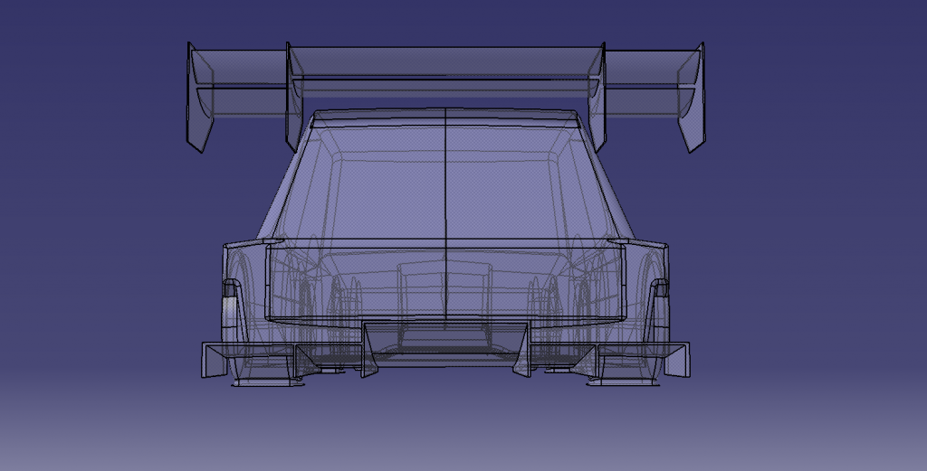
That's an untested experiment at the moment and should be run in the next few days. The current configuration doesn't have the square bits on the arch extensions and stands at 220kg downforce with a balance within 1% of the weight distribution. 200kg was the target so I'm looking to reduce drag now.
Word is that I should have my dampers by the end of the week, and lots more CNC parts are on their way so the car should be on it's wheels soon enough.
I've been hiding inside due to the holidays and s
t weather, so nothing has progressed on the build.. but I have been doing lots of CFD work trying to sort the bodywork & aero out. Here's how things look at the moment:205 6R4
That's an untested experiment at the moment and should be run in the next few days. The current configuration doesn't have the square bits on the arch extensions and stands at 220kg downforce with a balance within 1% of the weight distribution. 200kg was the target so I'm looking to reduce drag now.
Word is that I should have my dampers by the end of the week, and lots more CNC parts are on their way so the car should be on it's wheels soon enough.
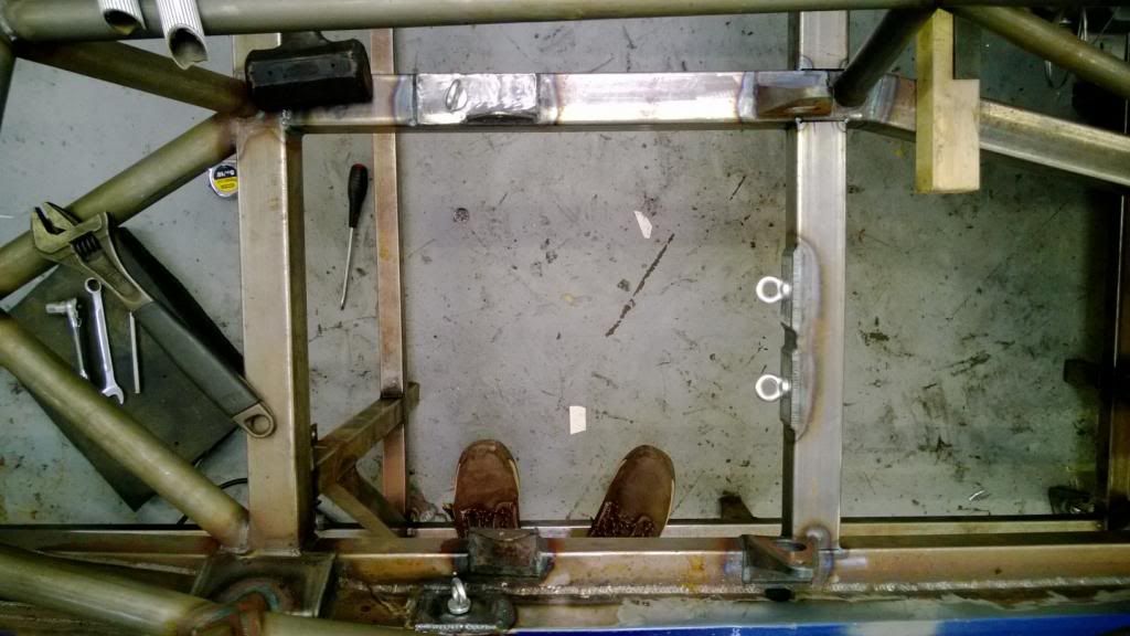
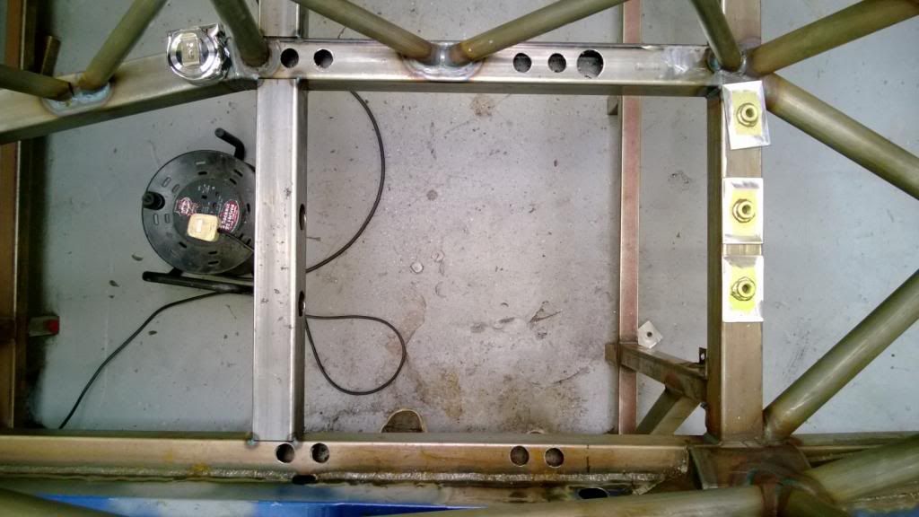
Ok, so a small update for the first of the year.. I had a few hours this weekend where it was nice enough to go and do some work, so I got started on the harness mounts. I got a bar with the anti-sub mounting points sorted, then moved on to the lap belt points and ran in to a problem - there just isn't space to get the inboard mount in place.
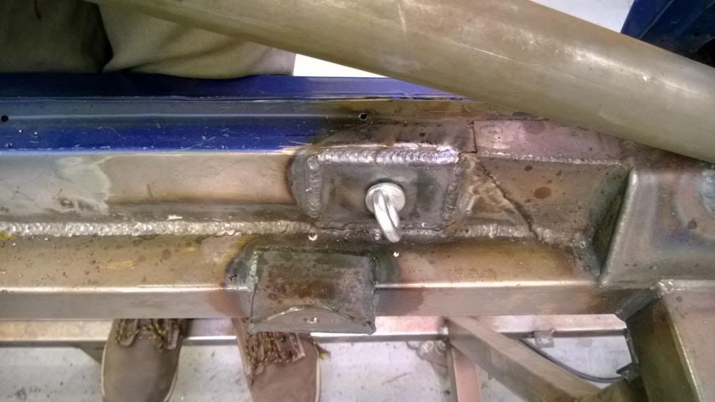
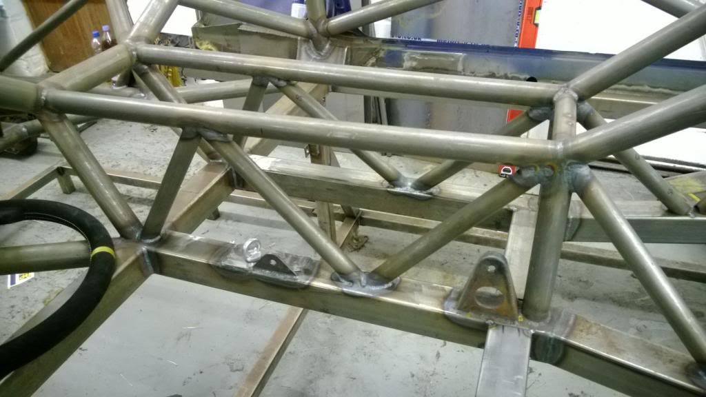
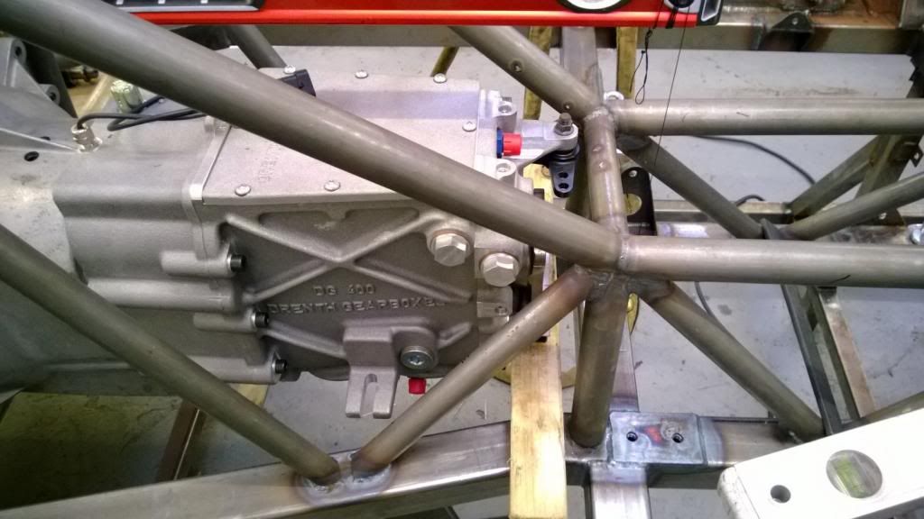
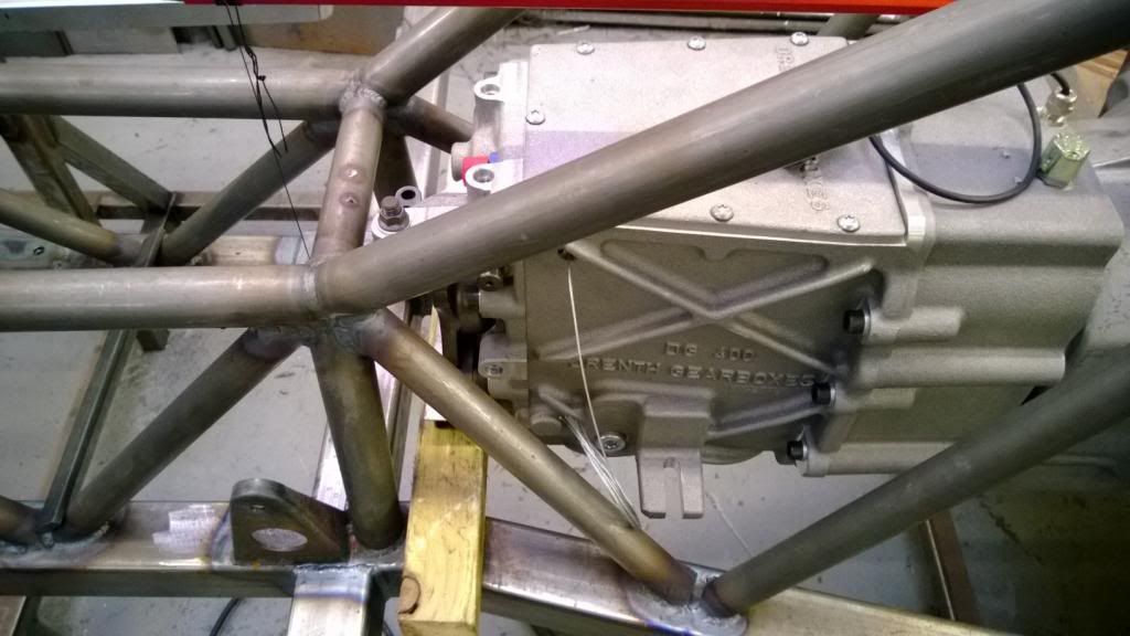
The pic below(sort of) shows the problem.. the mounting eye will go just behind the rear seat mounting bracket, but the diagonal brace gets in the way. Handily I left these tacked until I could check clearance, so it isn't a big job to modify.
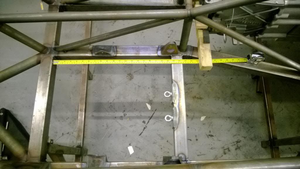
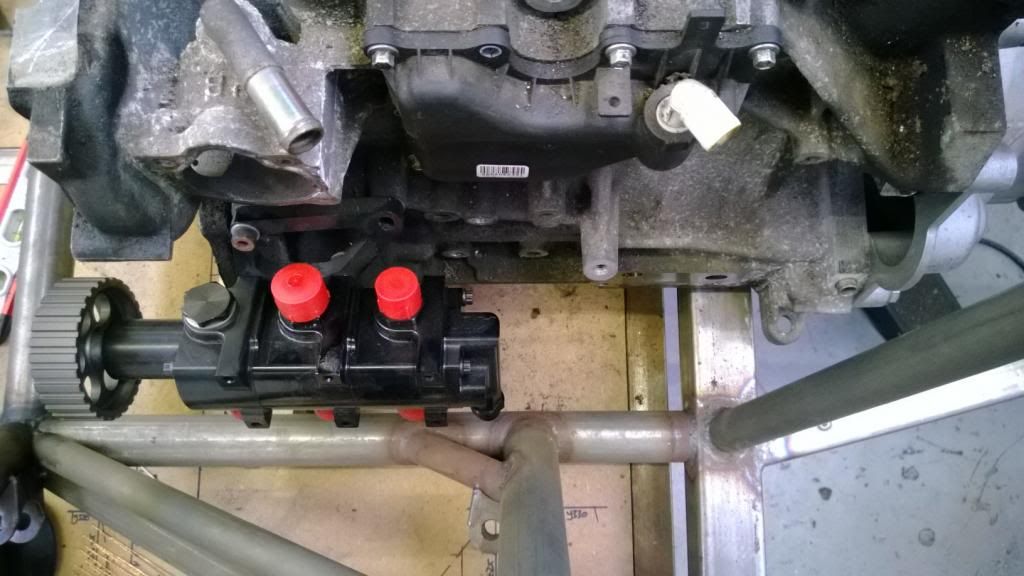
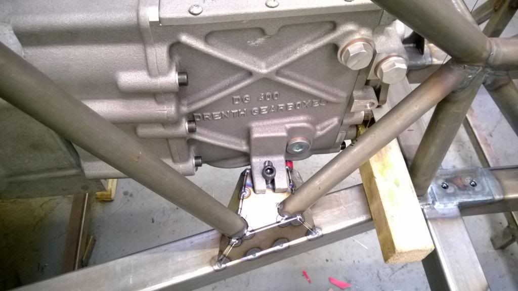
While I'm moving braces, I'm also going to move these front ones as it fouls on the gearbox fill plug.
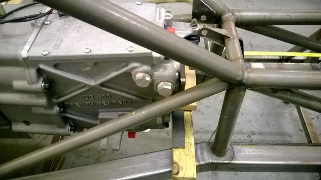
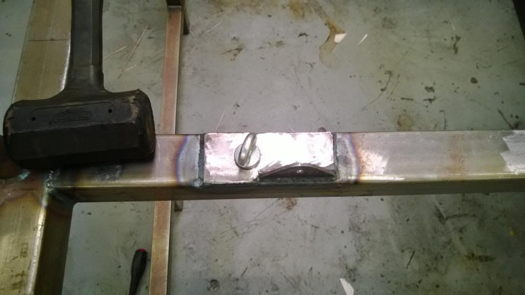
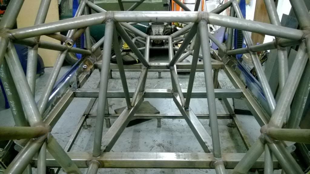
This will be the solution:
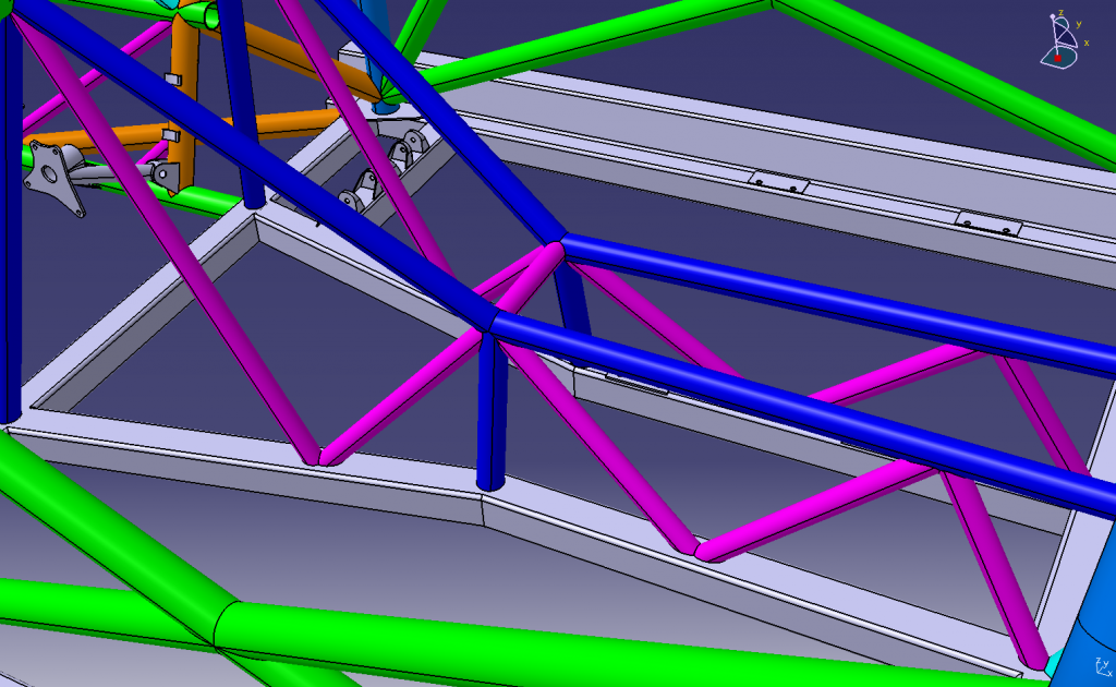
Handily, the intersection of the front two braces is where the gearbox mounts will be, so will help stiffen that area up a lot - every cloud..
The pic below(sort of) shows the problem.. the mounting eye will go just behind the rear seat mounting bracket, but the diagonal brace gets in the way. Handily I left these tacked until I could check clearance, so it isn't a big job to modify.
While I'm moving braces, I'm also going to move these front ones as it fouls on the gearbox fill plug.
This will be the solution:
Handily, the intersection of the front two braces is where the gearbox mounts will be, so will help stiffen that area up a lot - every cloud..

Ok, so I have given Photobucket some money and now have unlimited bandwidth on the pictures.
I had a few hours today, finishing the harness mounts..
First of all, I got my MIG out and laid some big old slugs around the RH mounting plate:
Then modified & extended the LH seat mount:
Then added a very short harness bar, which will have some threaded bosses welded in to it when I get hold of some more:
Then jumped in for a quick selfie!
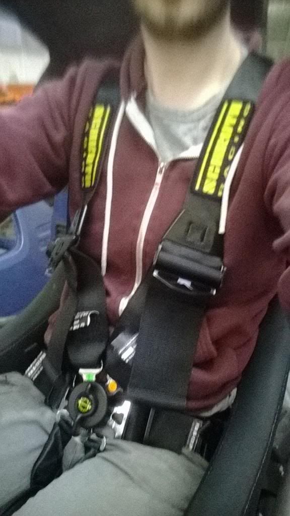
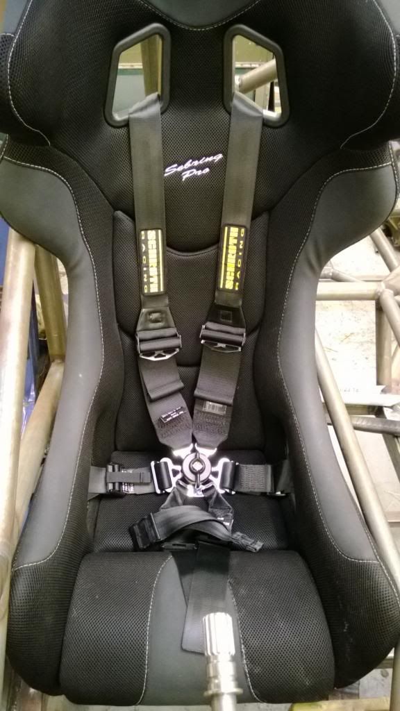
Since I'll be using a HANS, the shoulder straps need to cross over in order to sit at the correct angle:
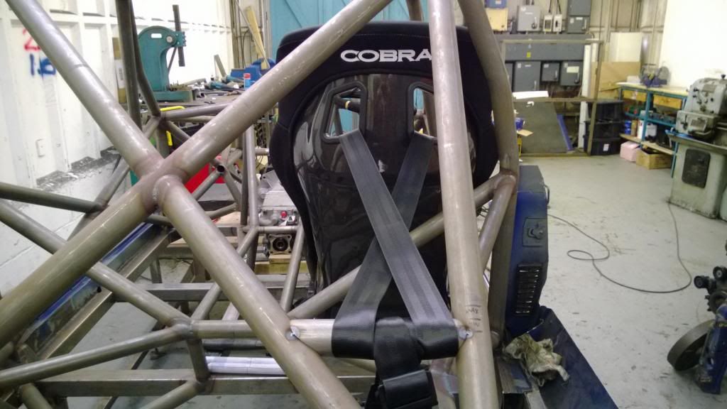
So that's one fiddly little job out the way! I'm going to do the same for the passenger side, as I would like to be able to take people out in it every now and then.. but I need to get hold of some more threaded bosses first.
I had a few hours today, finishing the harness mounts..
First of all, I got my MIG out and laid some big old slugs around the RH mounting plate:
Then modified & extended the LH seat mount:
Then added a very short harness bar, which will have some threaded bosses welded in to it when I get hold of some more:
Then jumped in for a quick selfie!
Since I'll be using a HANS, the shoulder straps need to cross over in order to sit at the correct angle:
So that's one fiddly little job out the way! I'm going to do the same for the passenger side, as I would like to be able to take people out in it every now and then.. but I need to get hold of some more threaded bosses first.
PROGRESS! 
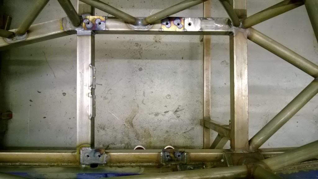
It was such a nice weekend for a change, so I went and had a proper session yesterday. First up, last weekend (around the miserable weather) I spent a couple of hours re-doing the transmission tunnel bracing to get clearance for the seat & harness mounts. Chopped out the old, glued in the new. I like it.
Awaiting gearbox mounts, then finished.
My friends will be pleased to hear that I decided to put in some passenger seat mounts! (Although I haven't yet decided I want to spend another grand on a passenger seat.. maybe I can get them all to chip in!) I wanted the mounts to be removable, so that if I don't get the same seat for that side I can just make up mounts to fit that, rather than be committed to one type of seat; so I fitted some weld-nuts to the backs of the plates.
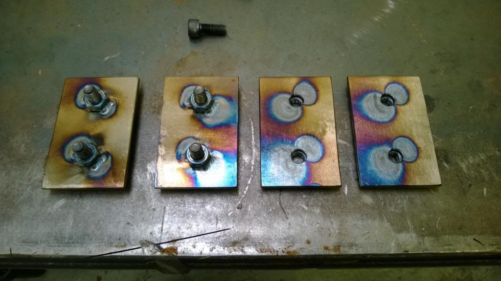
Then drilled a whole load of holes..
..tacked those bad boys in, and slapped some MIG around the old bodywork mounts.
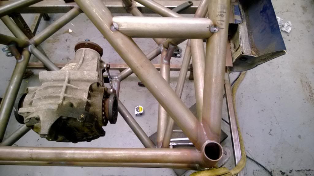
Then I set about making a new hairpiece.
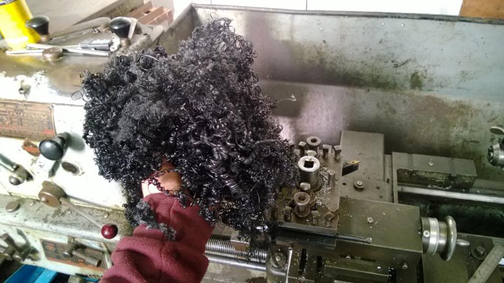
Making these bushes for the rear diff brace.. nylon is so nice to machine!
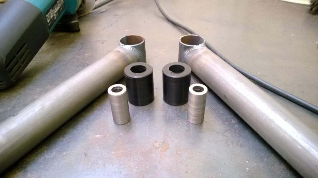
They press in to the end housings like so..
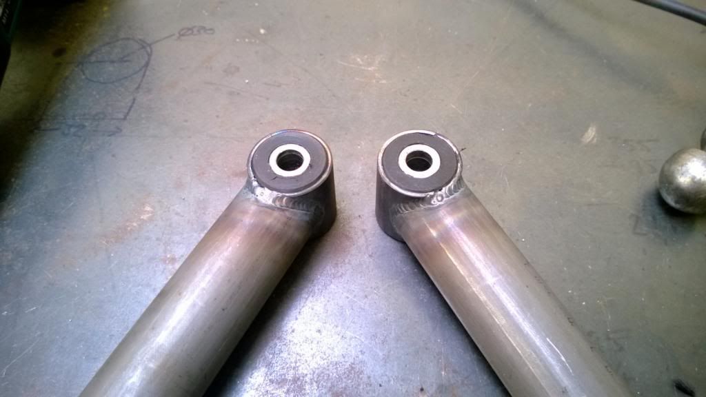
And those bits all go together to make the diff brace.
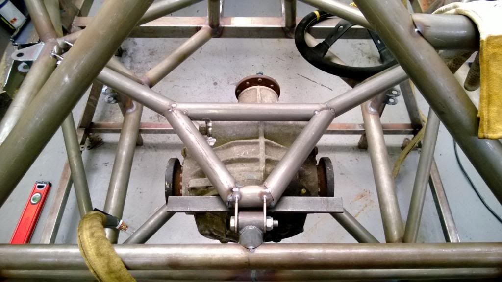
It comes out and everything!
I called it a day after that and went out on my bike.
It's so nice to have that bit done.. it's been a pain in the arse for a long time! This week I should get some more CNC bits for my suspension, so I should be able to start working on that next weekend.
It was such a nice weekend for a change, so I went and had a proper session yesterday. First up, last weekend (around the miserable weather) I spent a couple of hours re-doing the transmission tunnel bracing to get clearance for the seat & harness mounts. Chopped out the old, glued in the new. I like it.
Awaiting gearbox mounts, then finished.
My friends will be pleased to hear that I decided to put in some passenger seat mounts! (Although I haven't yet decided I want to spend another grand on a passenger seat.. maybe I can get them all to chip in!) I wanted the mounts to be removable, so that if I don't get the same seat for that side I can just make up mounts to fit that, rather than be committed to one type of seat; so I fitted some weld-nuts to the backs of the plates.
Then drilled a whole load of holes..
..tacked those bad boys in, and slapped some MIG around the old bodywork mounts.
Then I set about making a new hairpiece.
Making these bushes for the rear diff brace.. nylon is so nice to machine!
They press in to the end housings like so..
And those bits all go together to make the diff brace.
It comes out and everything!
I called it a day after that and went out on my bike.
It's so nice to have that bit done.. it's been a pain in the arse for a long time! This week I should get some more CNC bits for my suspension, so I should be able to start working on that next weekend.
Thanks trtj, the wing is limited in height by the regs - I can't have any aero higher than the max roof height. I have a new design that shows promise.. it's a two-element wing which is split in to 3 parts - the crentral 1.1m at a shallow angle of attack due to the flow off the roof, and the outer sections at a much higher angle. I need to upgrade my RAM before I finish that one off as the solution was taking comedy long.
I'll put some details and images of the CFD progress up once I have some good direction to show.. it's still very much in the experimental stage at the moment!
I'll put some details and images of the CFD progress up once I have some good direction to show.. it's still very much in the experimental stage at the moment!
Oooo I did see those panels the other day! Shame they're so expensive!
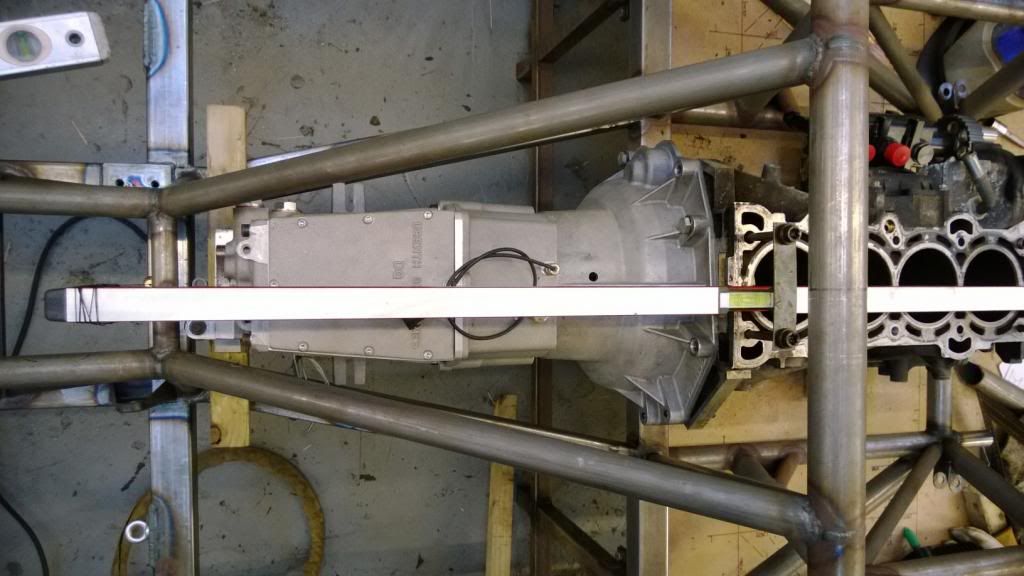
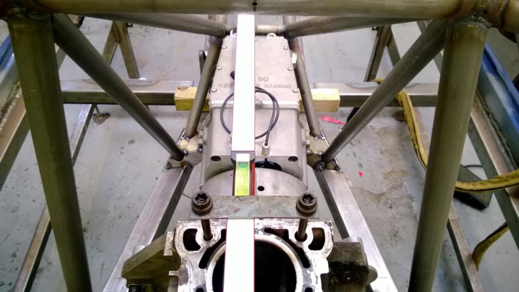
More work this weekend on the engine & gearbox mounts.. yesterday I got the engine and gearbox back in and spent some time getting it all straight and level. I made up some little straps to hold a spirit level on the centreline, then hung plumb lines off either end to get it lined up.
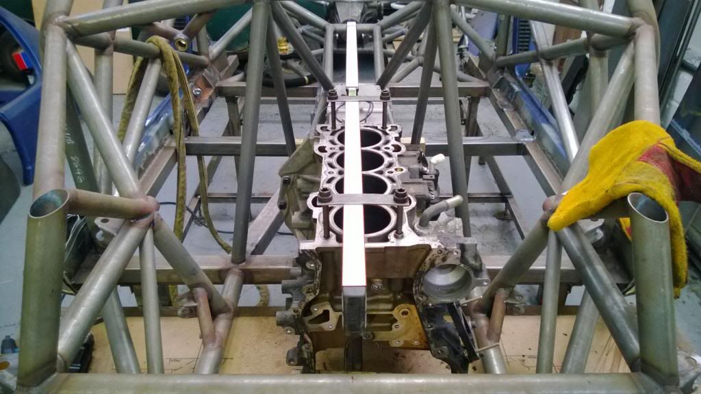
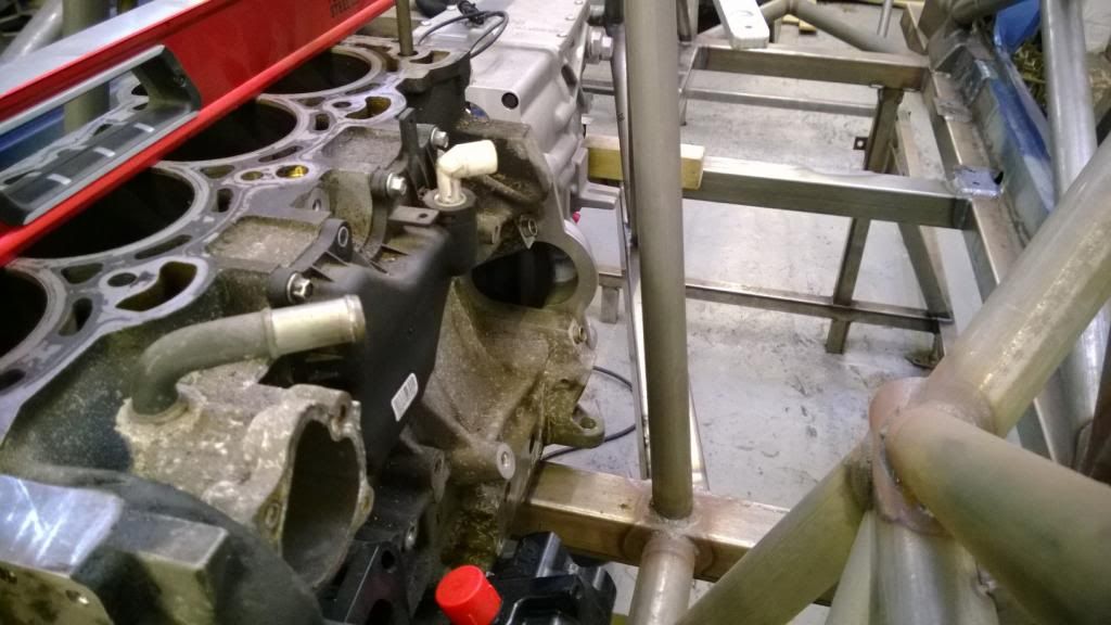
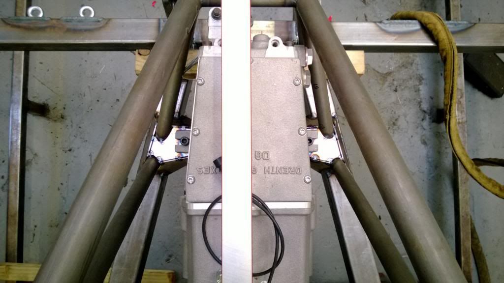
I immediately spotted a problem.. the bolt holes for the starter motor line up really very nicely with this chassis member! There was space, but just not enough to get a bolt in and be able to do it up, so I had to abandon having the engine offset and put it in the centre. It was offset 30mm to the LHS to counter driver weight and make room for the exhaust.
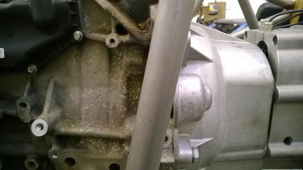
There was space, but trying to get bolts in would be impossible!
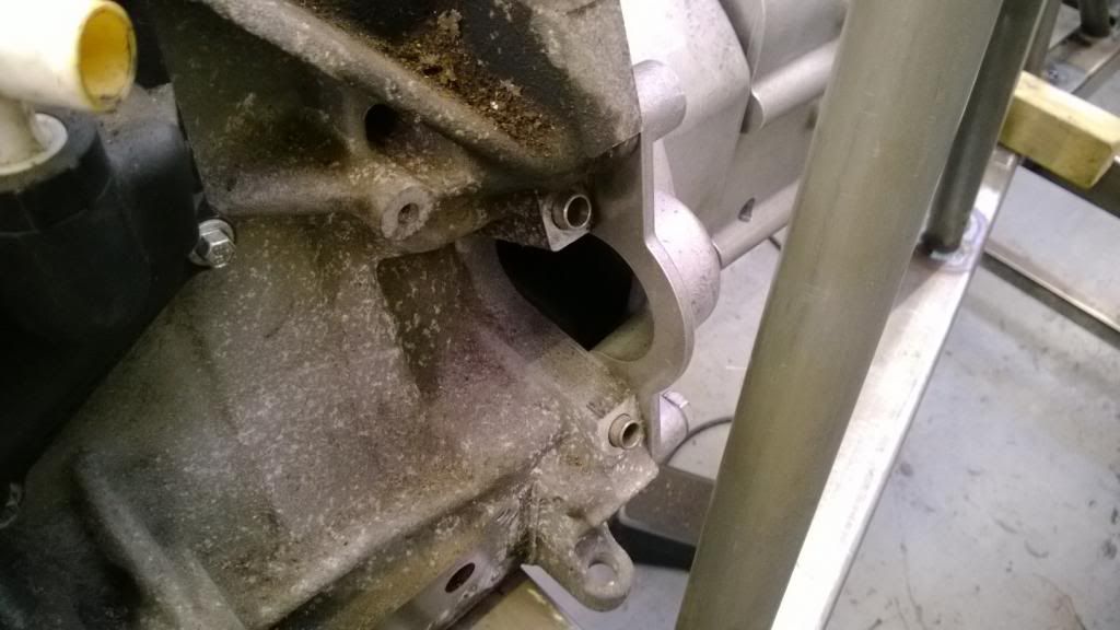
Space was also really tight around the oil pump & engine mount location.
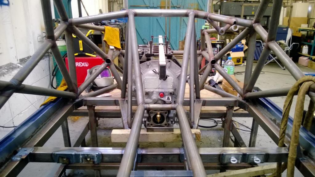
So I went and moved the engine as far back as I possibly could and put the crank line on the centreline of the vehicle, which got me enough room to be able to slip a bolt in and do it up. Thank feck for that, because an engine-out starter swap would have been absurd!
Tight, but enough:
Crank line is now central:
So today (around setting myself on fire (yes I did get pics)) I used some Cardboard Aided Design to make the gearbox mounts.
Then I was going to start on the engine mounts, but found that the plates & spacers I'd had water cut weren't quite right.. by the time I had opened the holes up enough to fit I wasn't happy with the amount of material left, so will have to get some new ones made up with revised hole positions.
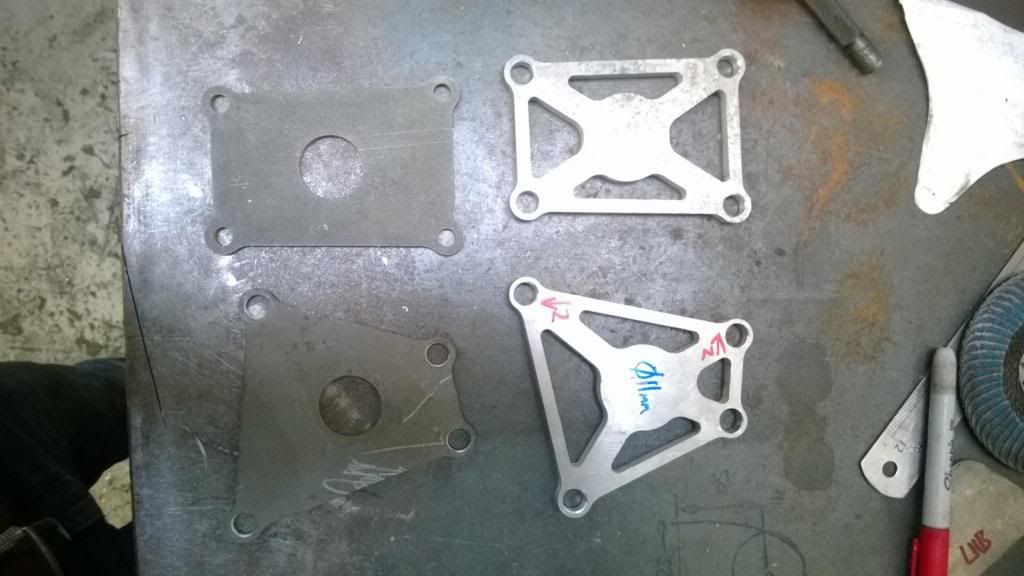
That's all for now.. I have a few pics of my wheels & brakes now that the centre bores have been machined out and everything fits, but will post tomorrow.
More work this weekend on the engine & gearbox mounts.. yesterday I got the engine and gearbox back in and spent some time getting it all straight and level. I made up some little straps to hold a spirit level on the centreline, then hung plumb lines off either end to get it lined up.
I immediately spotted a problem.. the bolt holes for the starter motor line up really very nicely with this chassis member! There was space, but just not enough to get a bolt in and be able to do it up, so I had to abandon having the engine offset and put it in the centre. It was offset 30mm to the LHS to counter driver weight and make room for the exhaust.
There was space, but trying to get bolts in would be impossible!
Space was also really tight around the oil pump & engine mount location.
So I went and moved the engine as far back as I possibly could and put the crank line on the centreline of the vehicle, which got me enough room to be able to slip a bolt in and do it up. Thank feck for that, because an engine-out starter swap would have been absurd!
Tight, but enough:
Crank line is now central:
So today (around setting myself on fire (yes I did get pics)) I used some Cardboard Aided Design to make the gearbox mounts.
Then I was going to start on the engine mounts, but found that the plates & spacers I'd had water cut weren't quite right.. by the time I had opened the holes up enough to fit I wasn't happy with the amount of material left, so will have to get some new ones made up with revised hole positions.
That's all for now.. I have a few pics of my wheels & brakes now that the centre bores have been machined out and everything fits, but will post tomorrow.
As promised..
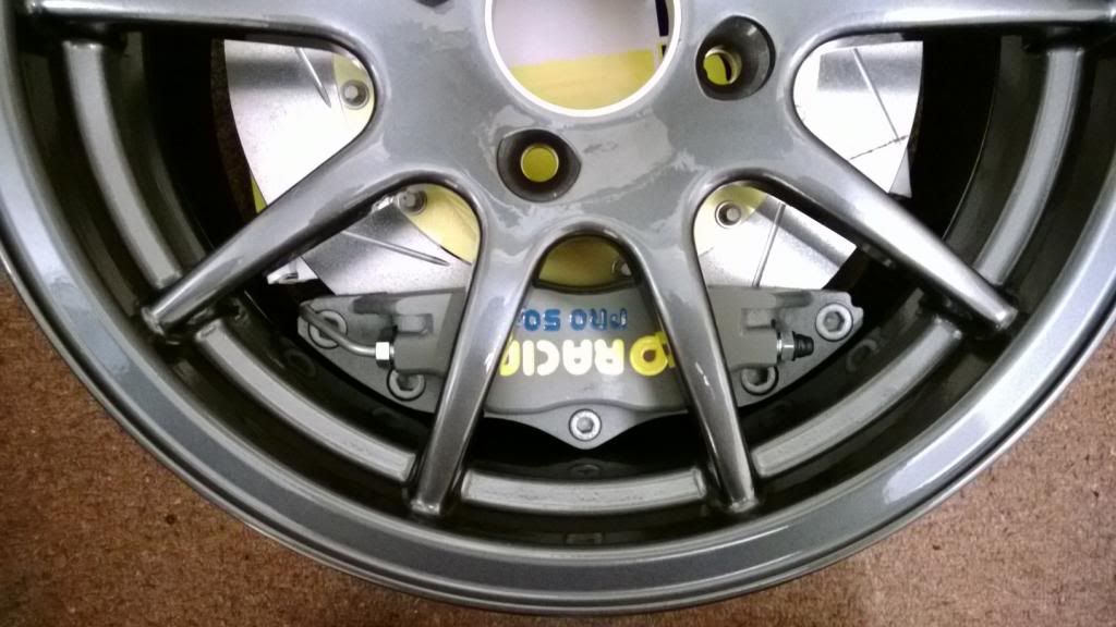
My wheels came back from having the centre bores machined, so I stuck the front brakes in and took some pictures.
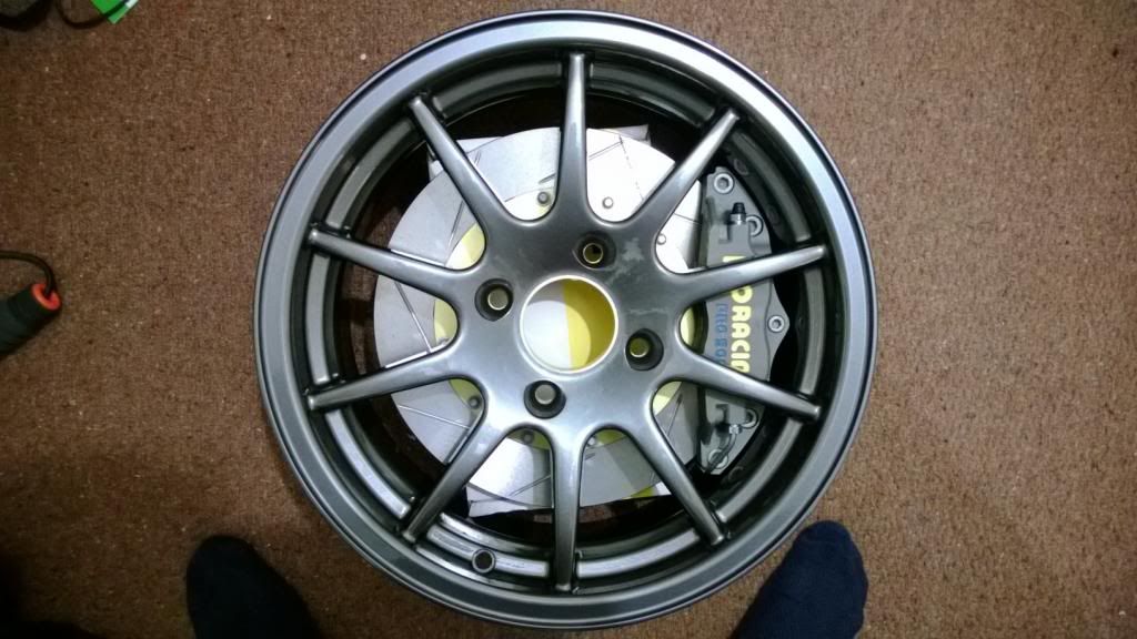
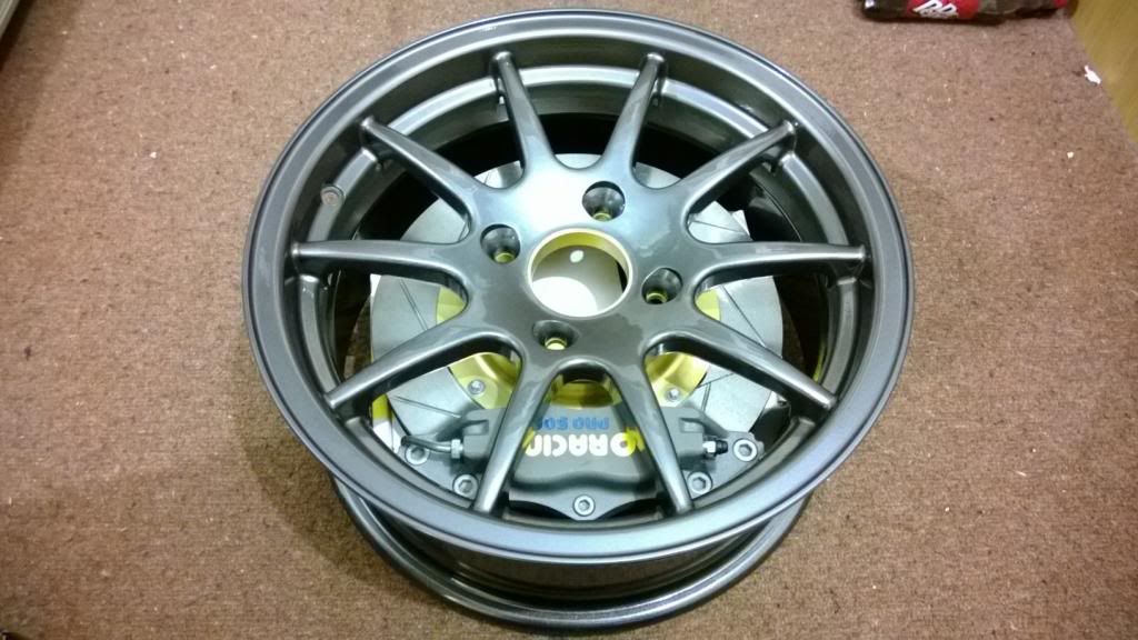
Nothing says motorsport like brakes that barely fit in the wheels.
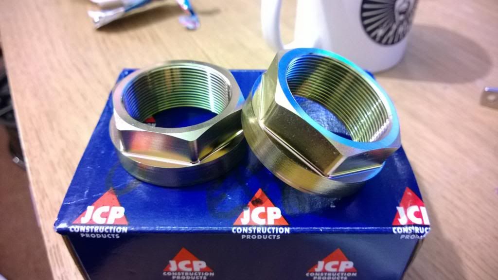
I also got my hub nuts (CNC & coated) back.. for such a seemingly insignificant part I think they look bloody awesome.
My wheels came back from having the centre bores machined, so I stuck the front brakes in and took some pictures.
Nothing says motorsport like brakes that barely fit in the wheels.
I also got my hub nuts (CNC & coated) back.. for such a seemingly insignificant part I think they look bloody awesome.
Haha yeah I was on the FS team at Herts uni in.. err.. 2010? What about you?
I did have a mate do a laser scan for me of a 205 body, but it was on metallic paint so the surface was pretty soft and difficult to extract. In the end I just used it as a silhouette to adjust what I'd already done to the right sort of shape. I'd love to get hold of a FARO arm or similar so I could digitise a mesh on the body and use that to generate surfaces.. in my limited surfacing experience I'd find that much easier to use!
I did have a mate do a laser scan for me of a 205 body, but it was on metallic paint so the surface was pretty soft and difficult to extract. In the end I just used it as a silhouette to adjust what I'd already done to the right sort of shape. I'd love to get hold of a FARO arm or similar so I could digitise a mesh on the body and use that to generate surfaces.. in my limited surfacing experience I'd find that much easier to use!
Ian - I think having studs would just make the problem worse! At least with bolts I only have to pull the starter away from the block 8mm to clear the dowels.
OlberJ - Yeah it'll be even tighter! I don't have a starter yet, but rest assured I will be getting one very soon to check. I know which one I will use and the part that bolts to the block is very slim, so I'm reasonably confident it'll be ok. Still.. I have to check!
Max Torque - It's solid mounted! The engine mounts will have nylon bushes but how much deflection that will allow I don't know. How much expansion are we talking here? I know exhausts have a habit of expanding some 20mm along the whole length, but that's a few metres of tube and several hundred degrees.. the block & box are quite a bit shorter and cooler so I can't see it being quite as extreme.
Appreciate the comments, guys.
Gassing Station | Readers' Cars | Top of Page | What's New | My Stuff