Peugeot 205 Saloon Libre - RWD Space-Frame Silhouette Racer
Discussion


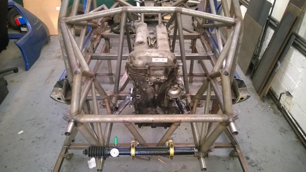
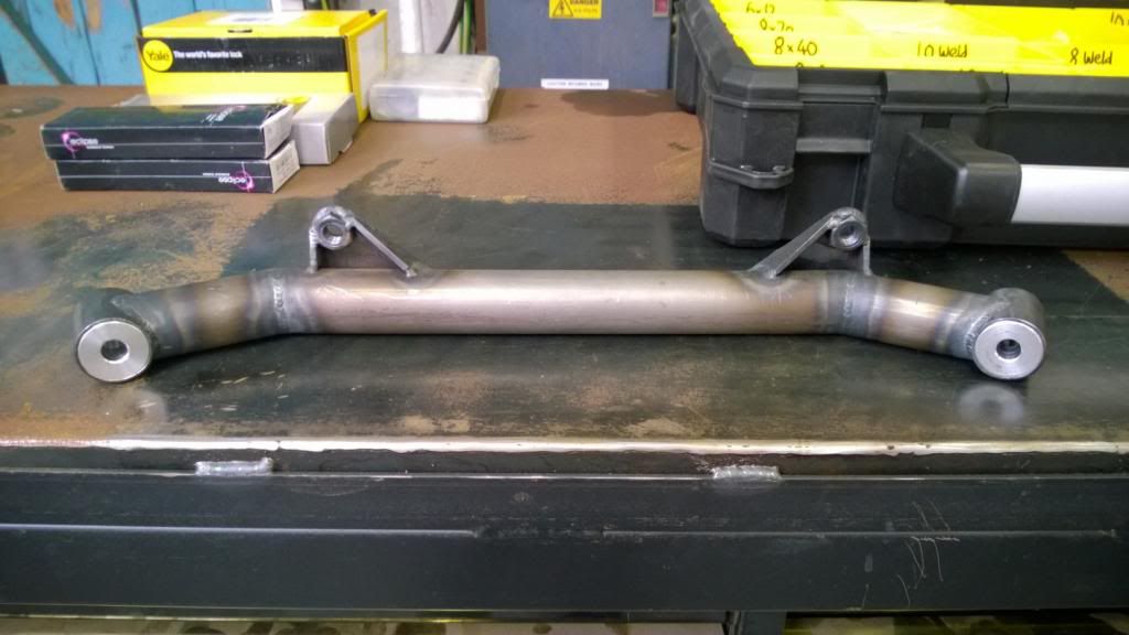
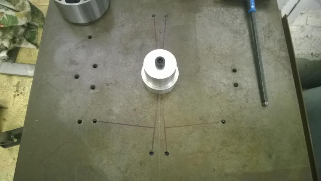
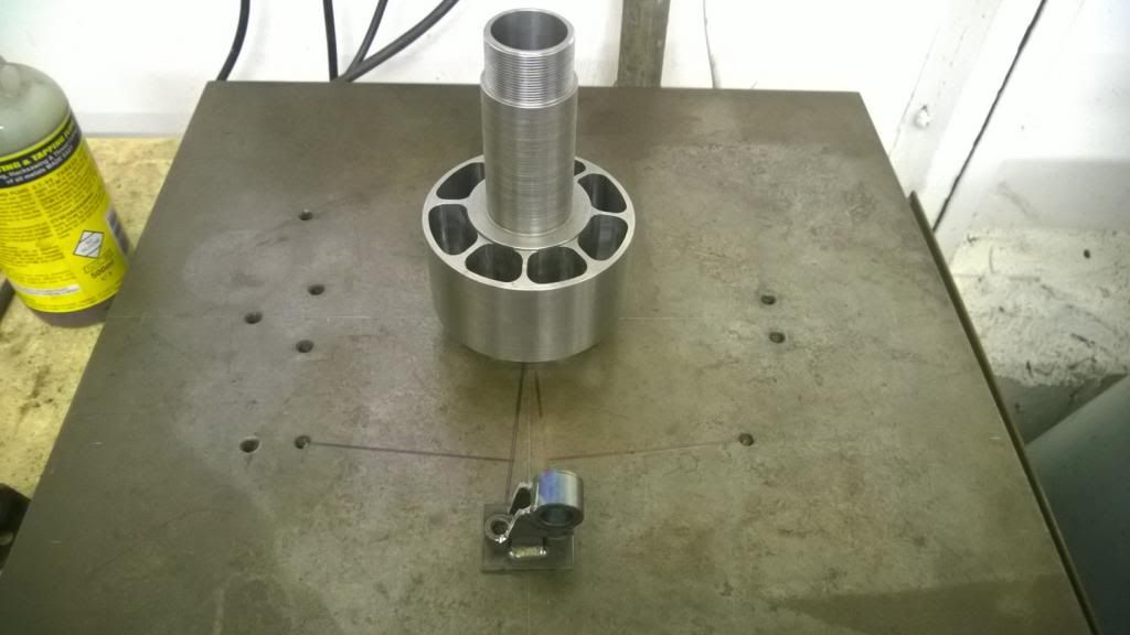
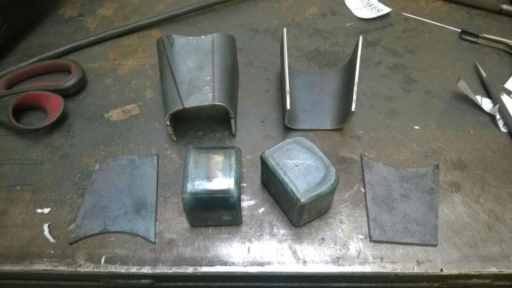
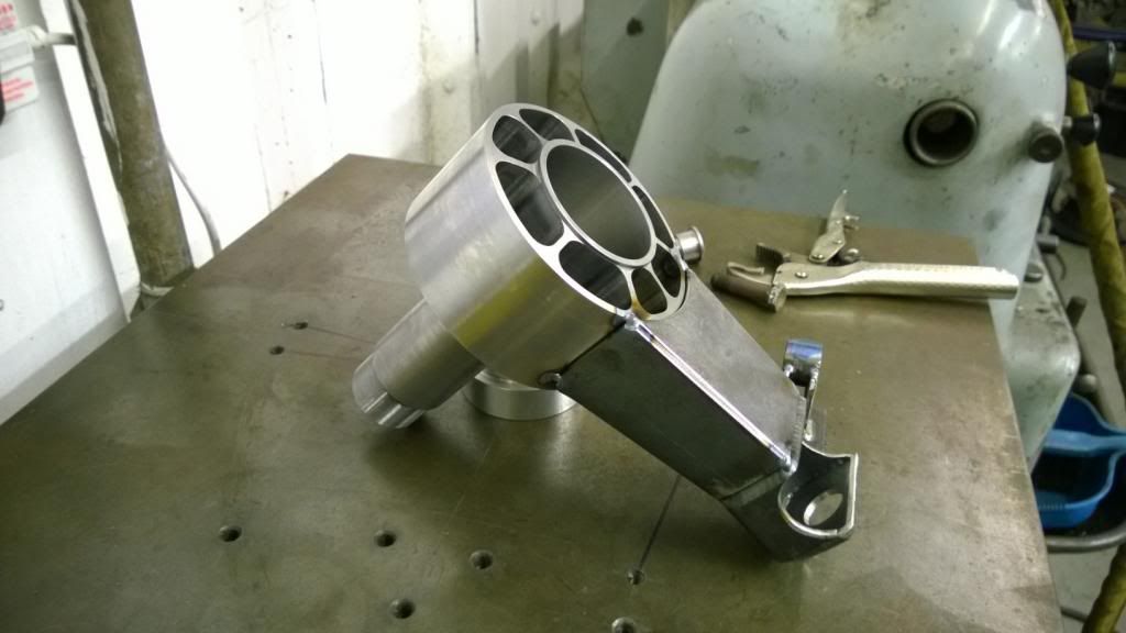
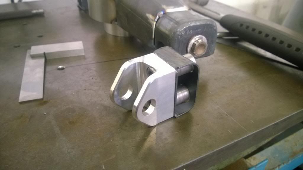
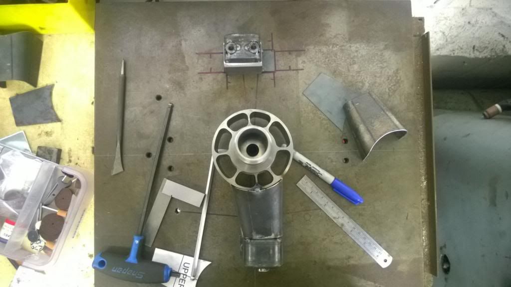
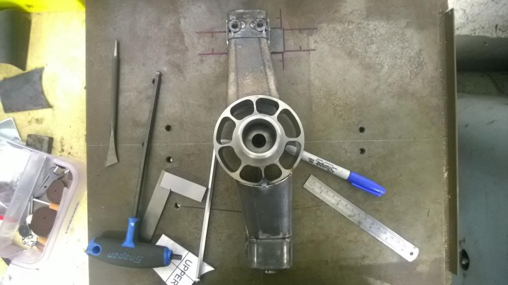
More work today.. sorting the steering rack mounts while I wait for the engine mount plates to be cut.
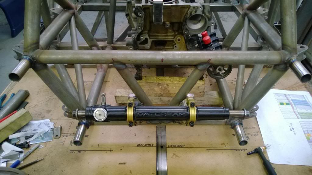
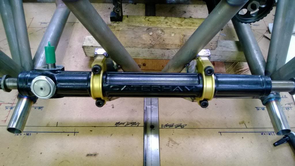
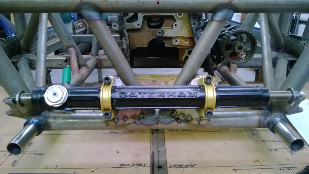
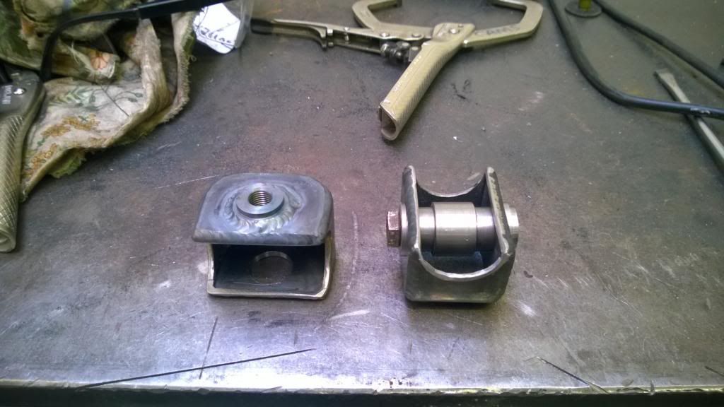
I love these clamps.. they came out so nicely! I borrowed some design ideas from a BMX stem I have - with the top bolt tight you can still twist the rack in the mounts, then the lower bolt has a small gap so that when you tighten that bolt down, everything is solid.
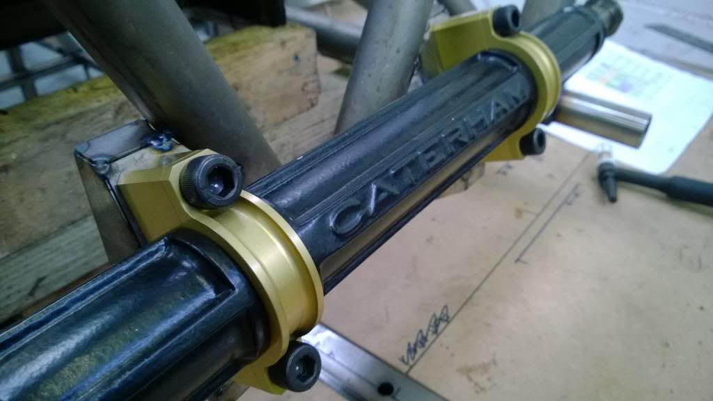
I love these clamps.. they came out so nicely!
I borrowed some design ideas from a BMX stem I have - with the top bolt tight you can still twist the rack in the mounts, then the lower bolt has a small gap so that when you tighten that bolt down, everything is solid. Nothing motivates me more than good weather, and it was so nice this weekend! There's something I love about heading out early when it's cold but the sun is up. Anyway.. engine mounts!
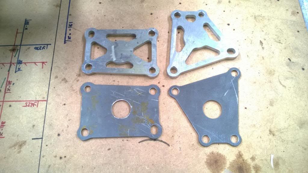
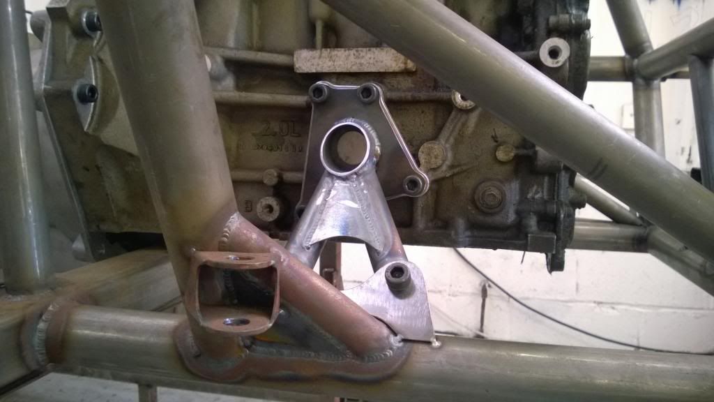
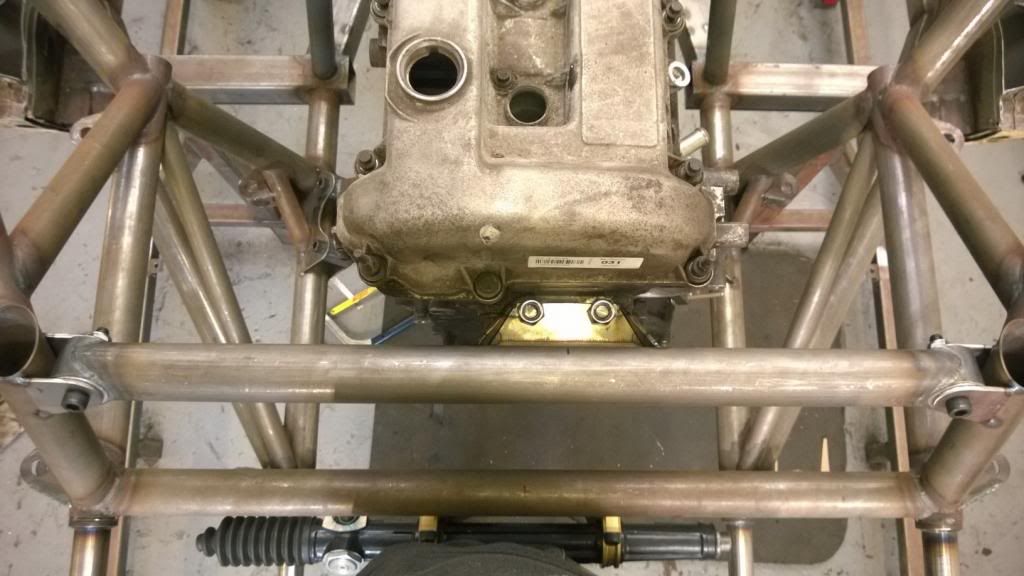
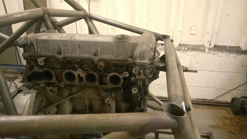
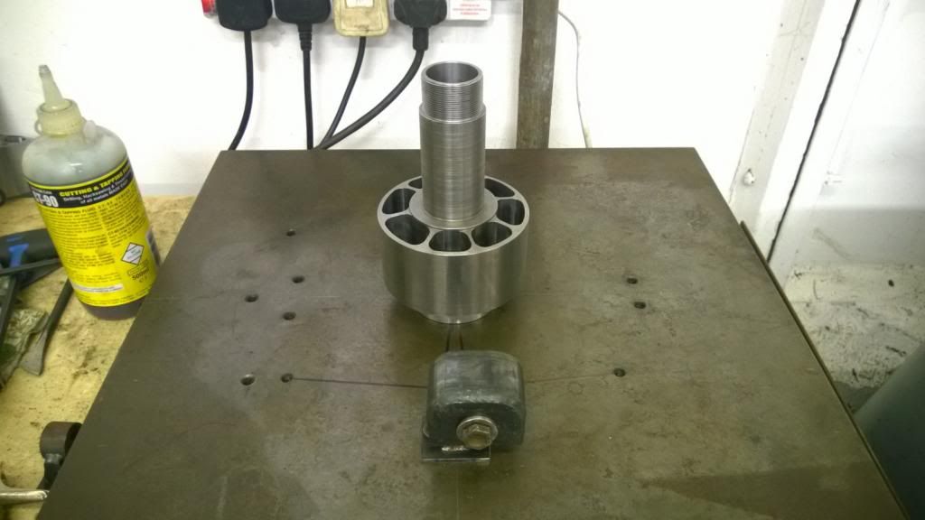
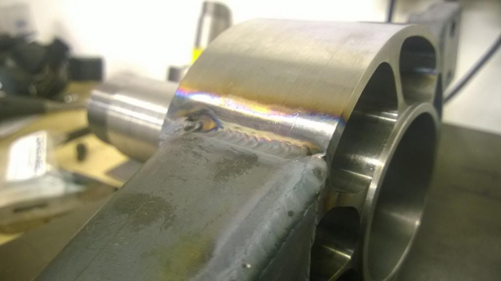
I got my new plates & spacers back from the water jet profiler, and hurrah they now fit both my engine blocks! I turned some aluminium bushes up and pressed them in to some tube, then profiled and tacked everything together.
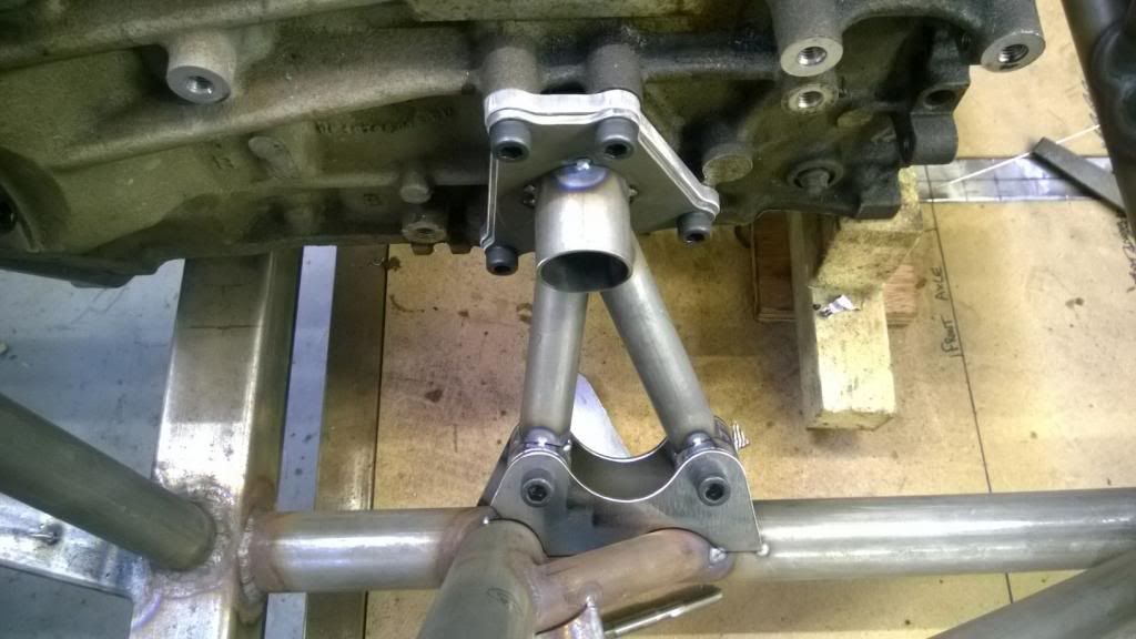
Clearance round the oil pump is very tight!
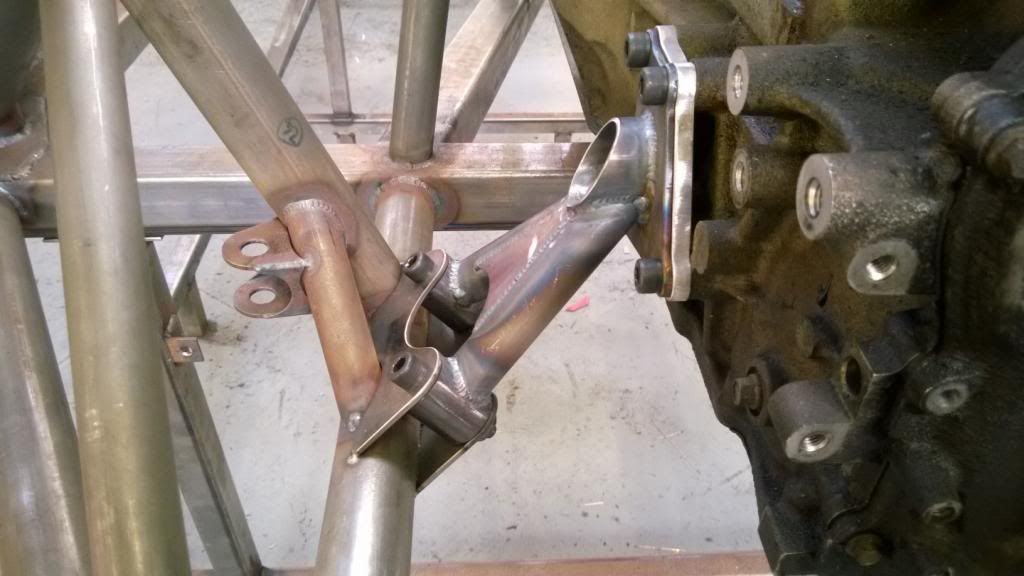
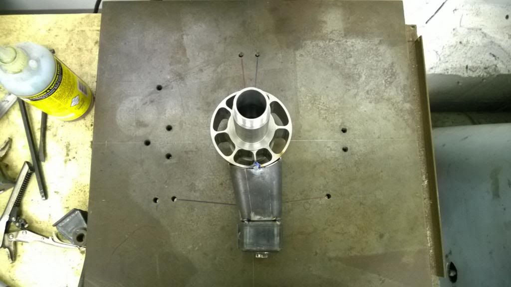
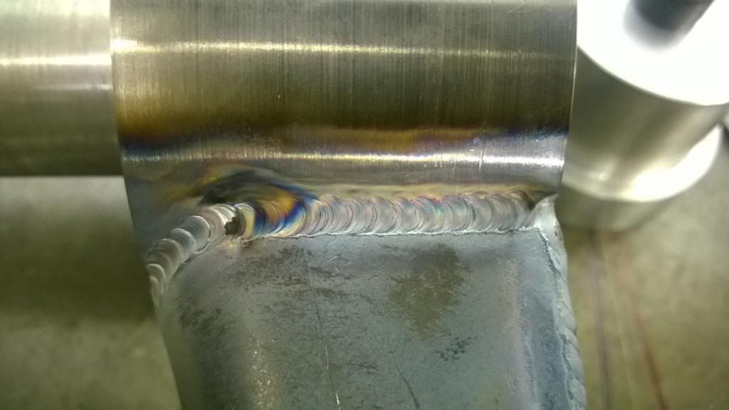
Slight problem there, being that I couldn't get to one of the screws once the front leg was on! So that had to come off for a re-think, and I fitted a piece of tube to allow me to get a tool in there to do it up.
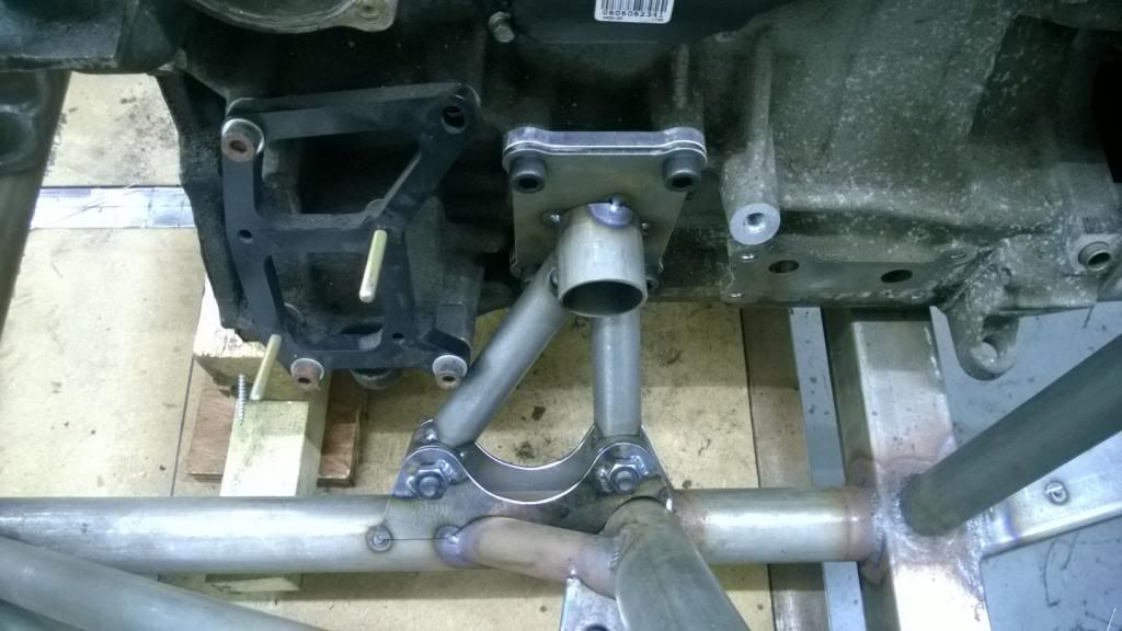
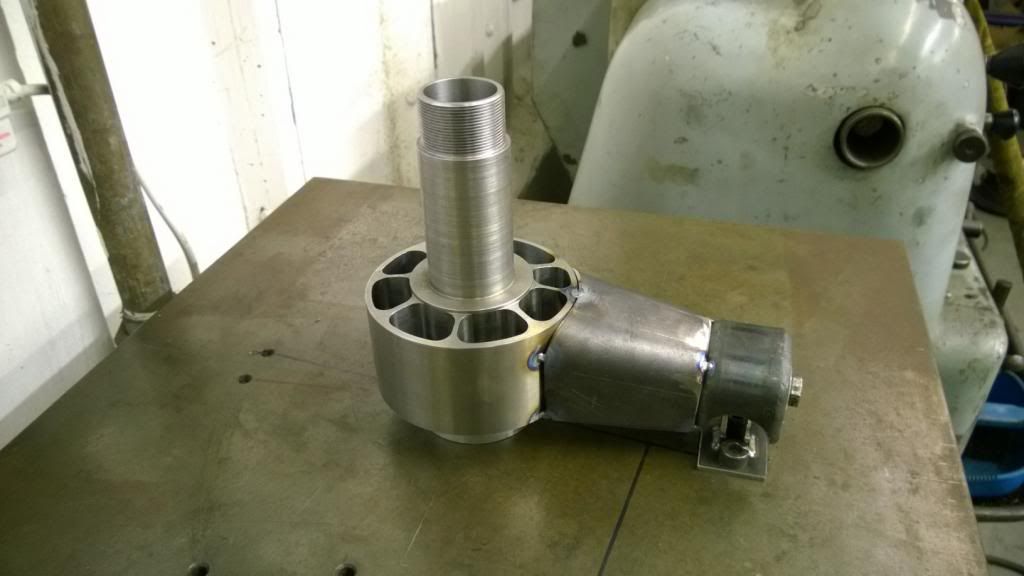
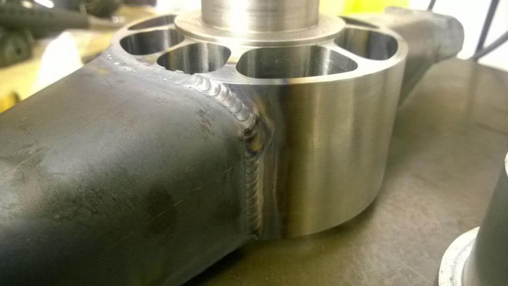
So then it was a case of welding it all up and fitting some simple gussets.
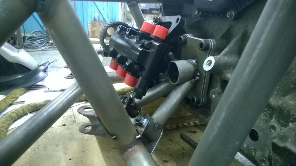
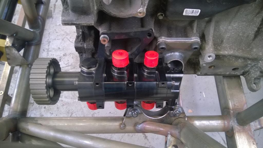
Oil pump still fits, which is nice.
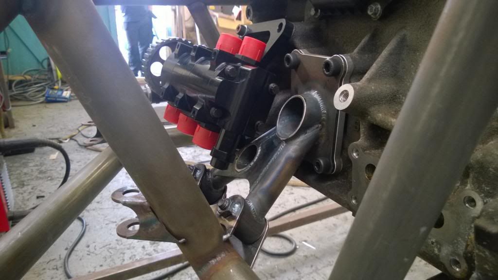
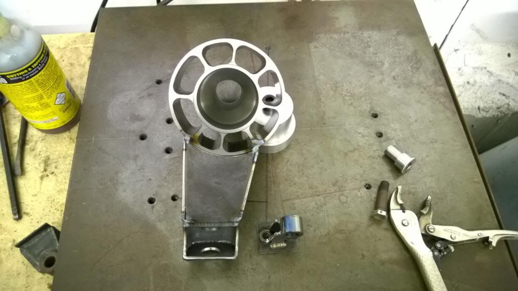
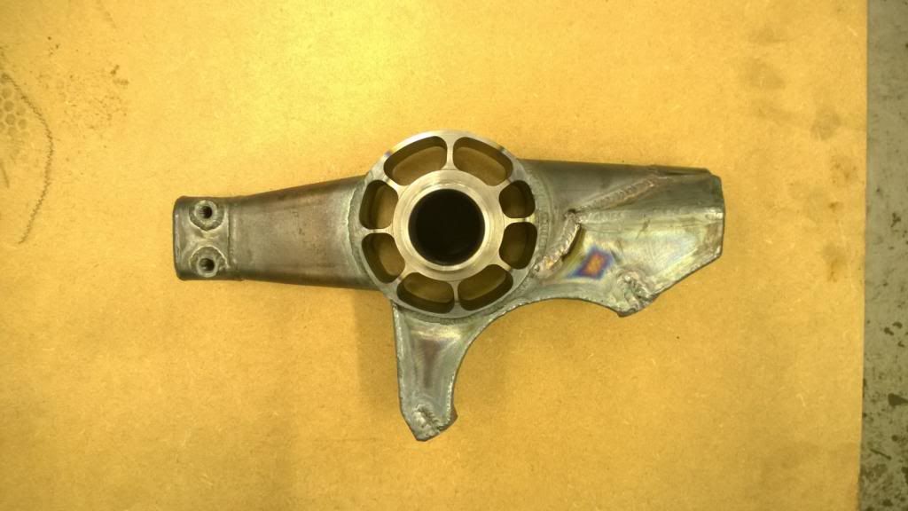
All done! I threw the head and cam cover on, then removed the front half of the jig table so I can do some welding during the week.
I got my new plates & spacers back from the water jet profiler, and hurrah they now fit both my engine blocks! I turned some aluminium bushes up and pressed them in to some tube, then profiled and tacked everything together.
Clearance round the oil pump is very tight!
Slight problem there, being that I couldn't get to one of the screws once the front leg was on! So that had to come off for a re-think, and I fitted a piece of tube to allow me to get a tool in there to do it up.
So then it was a case of welding it all up and fitting some simple gussets.
Oil pump still fits, which is nice.
All done! I threw the head and cam cover on, then removed the front half of the jig table so I can do some welding during the week.
Edited by CamMoreRon on Sunday 9th March 18:43
Approximately zero percent - the way it should be!
You wouldn't believe the amount of stick I used to get on an un-named 205 GTI enthusiast forum for claiming it was still a 205.
Thanks Ian.. I'm still struggling to find out what type of thread my steering rack (Caterham / Mk1 Fiesta) has for the inner balljoints. It's 7/8" x 20tpi from what I can measure.. but no idea what standard!
Thanks for the kind words.
Ok, so a small update this weekend.. Titanfall was released on Friday so frankly it's a wonder that I even made it out the house!
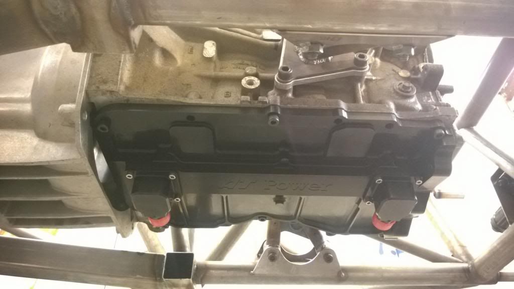
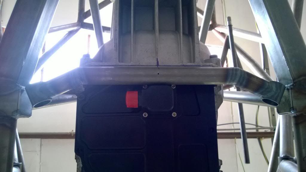
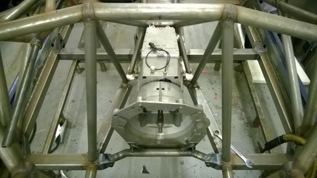
I made the front "strut brace" which also doubles up as a front engine mount.. it's pretty simple but was a little fiddly nonetheless.
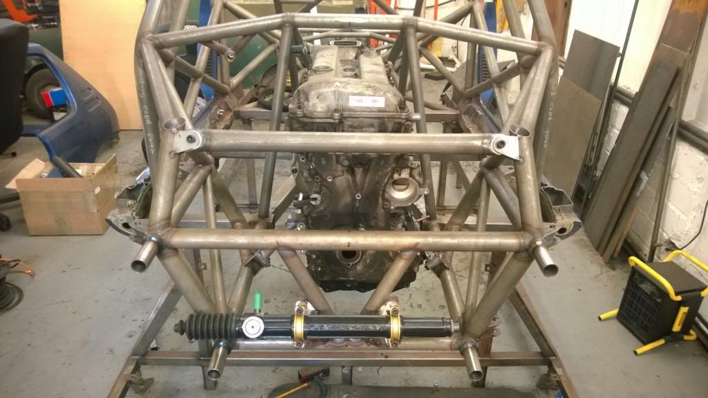
Then chopped out the central part of this box section, which will be replaced with a removable brace that bolts to the front of the bellhousing. Space for this is very very tight! I bolted the sump on, and will start making the brace (which is the last engine mount) next weekend.
That's all for now.. I have the week after next off so am hoping to get a lot done!
Ok, so a small update this weekend.. Titanfall was released on Friday so frankly it's a wonder that I even made it out the house!
I made the front "strut brace" which also doubles up as a front engine mount.. it's pretty simple but was a little fiddly nonetheless.
Then chopped out the central part of this box section, which will be replaced with a removable brace that bolts to the front of the bellhousing. Space for this is very very tight! I bolted the sump on, and will start making the brace (which is the last engine mount) next weekend.
That's all for now.. I have the week after next off so am hoping to get a lot done!
Thanks Kev, I'm hoping to get a lot done!
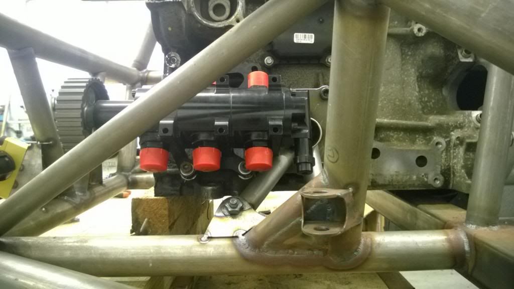
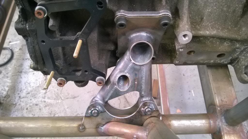
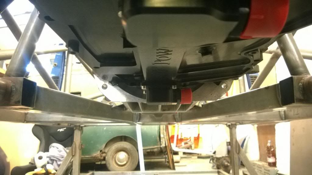
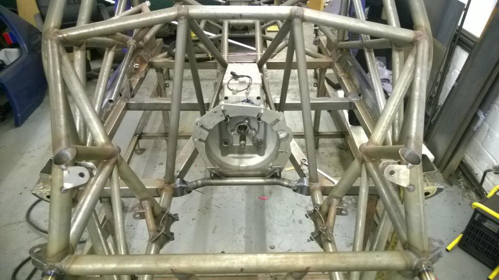
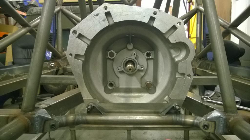
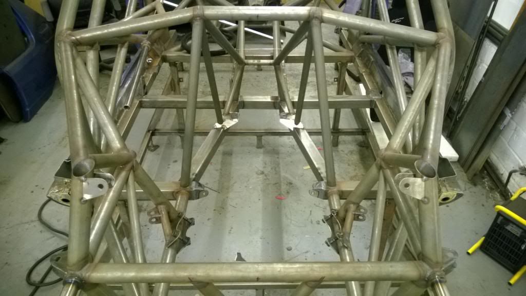
Update 1 of many: I made the last of the engine mounts today - a crossmember to tie the bottom of the chassis together and secure the front of the gearbox. I started off by making a close-out panel for the opening that is no longer covered by the wet sump pan, then got the bulk of the crossmember done by eye before tacking brackets to it in situ.
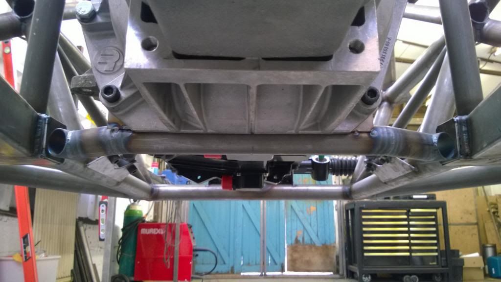
Clearance is very tight to the rear scavenge block! There's 3mm or so room, but neither are going anywhere so I'm not concerned.
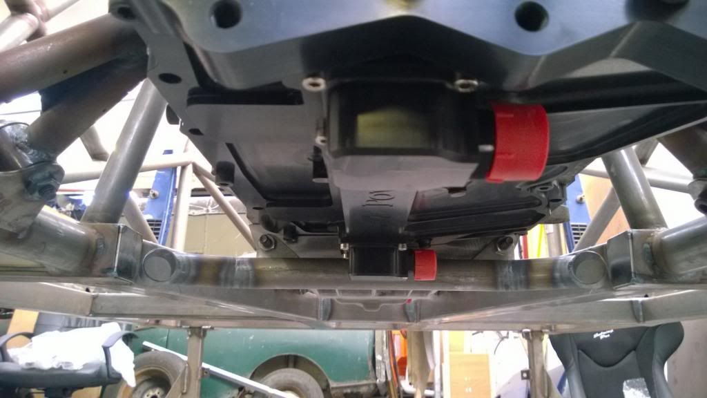
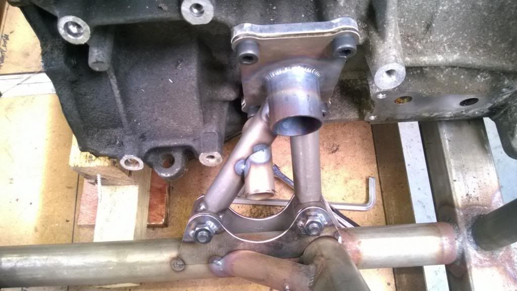
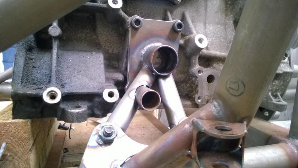
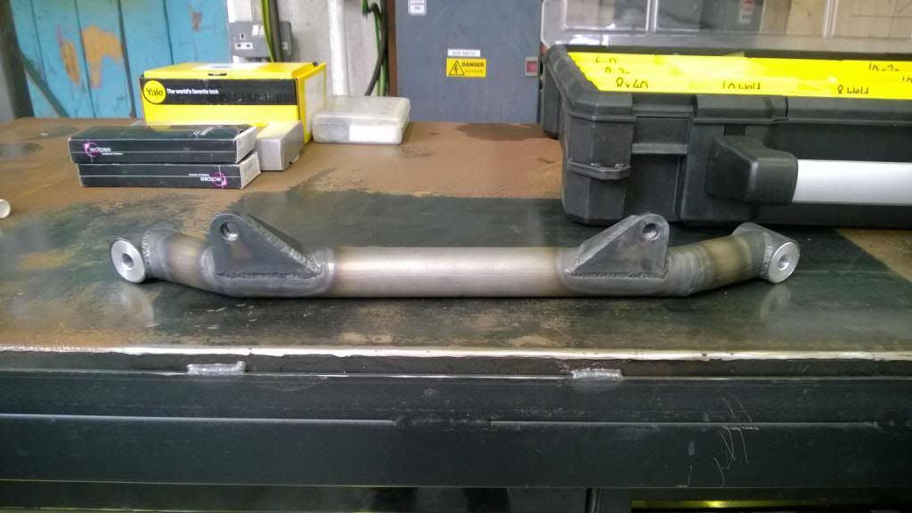
Then welded up the gearbox brackets with some captive nuts, and machined some aluminium bushes for the ends.
So with that I did a full engine-out test to make sure it was all possible. It's actually a really nice job, broken down in to a few manageable steps. The front strut brace & mount comes off, then the side engine mounts - leaving the engine attached to the box, then the engine comes straight out, then box comes off the crossmember & rear mounts to be lowered out the front to the ground. Nice.
Everything out!
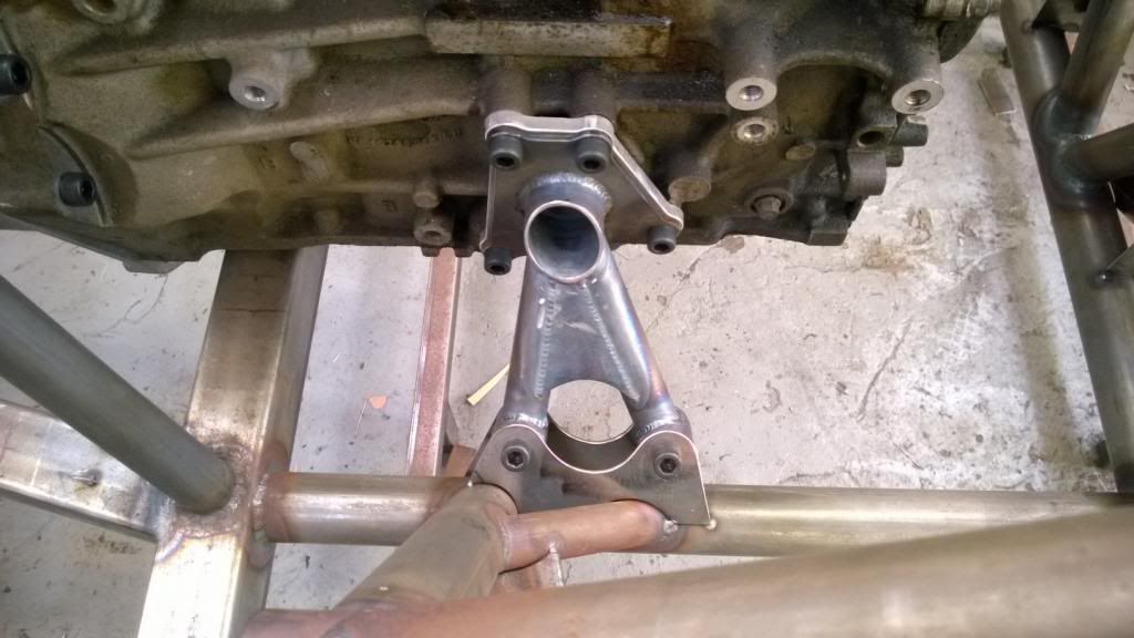
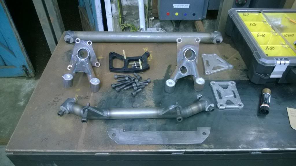
And a shot of all the mounts.
Update 1 of many: I made the last of the engine mounts today - a crossmember to tie the bottom of the chassis together and secure the front of the gearbox. I started off by making a close-out panel for the opening that is no longer covered by the wet sump pan, then got the bulk of the crossmember done by eye before tacking brackets to it in situ.
Clearance is very tight to the rear scavenge block! There's 3mm or so room, but neither are going anywhere so I'm not concerned.
Then welded up the gearbox brackets with some captive nuts, and machined some aluminium bushes for the ends.
So with that I did a full engine-out test to make sure it was all possible. It's actually a really nice job, broken down in to a few manageable steps. The front strut brace & mount comes off, then the side engine mounts - leaving the engine attached to the box, then the engine comes straight out, then box comes off the crossmember & rear mounts to be lowered out the front to the ground. Nice.
Everything out!
And a shot of all the mounts.

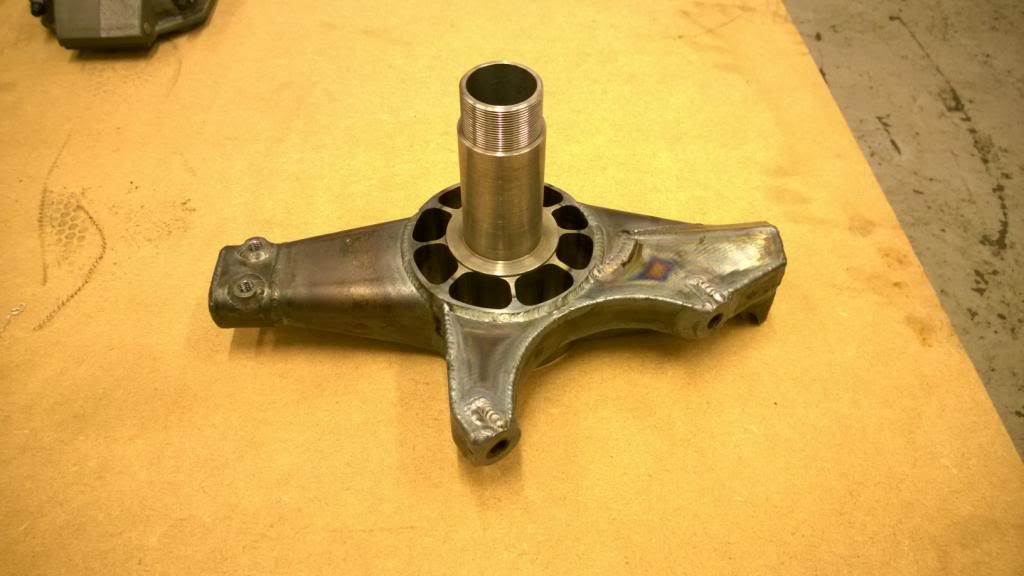
I've been working on the front uprights for the past couple of days, so here's a small update. It's 8pm and I still haven't eaten, so this'll be just pictures and a few words.
Drawings!
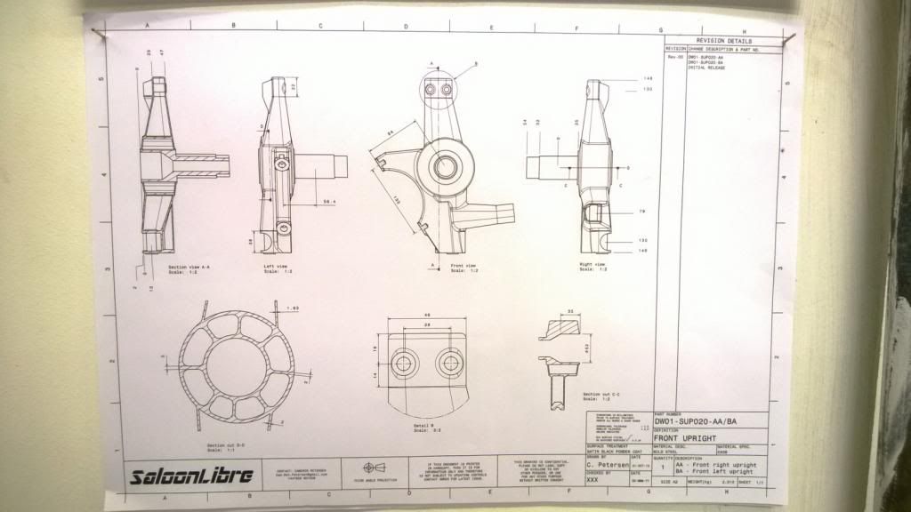
Which I used to mark out my "jig table"..
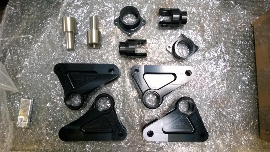
Machined a boss for the stub axle and made a little jig for the LBJ.
Then cut some bits out..
And got them in place..
That's all for now.. my pizza is done.
Drawings!
Which I used to mark out my "jig table"..
Machined a boss for the stub axle and made a little jig for the LBJ.
Then cut some bits out..
And got them in place..
That's all for now.. my pizza is done.
Edited by CamMoreRon on Tuesday 25th March 20:55
There we go!
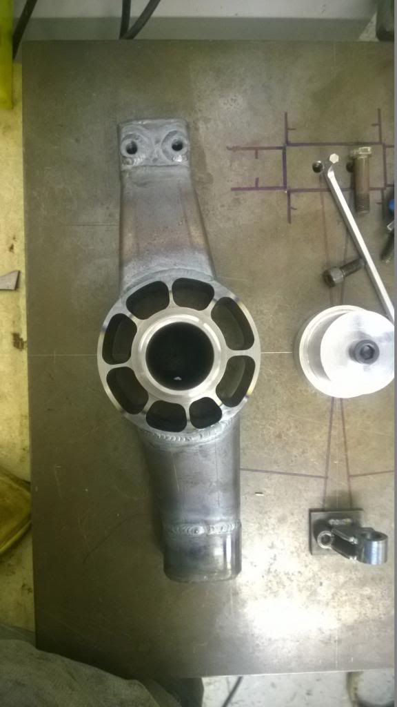
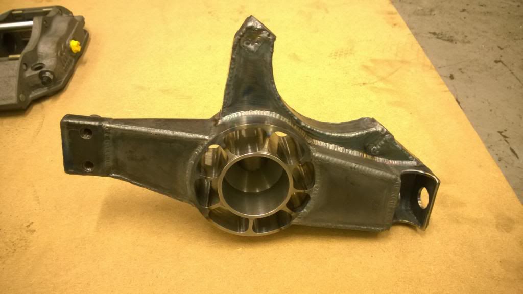
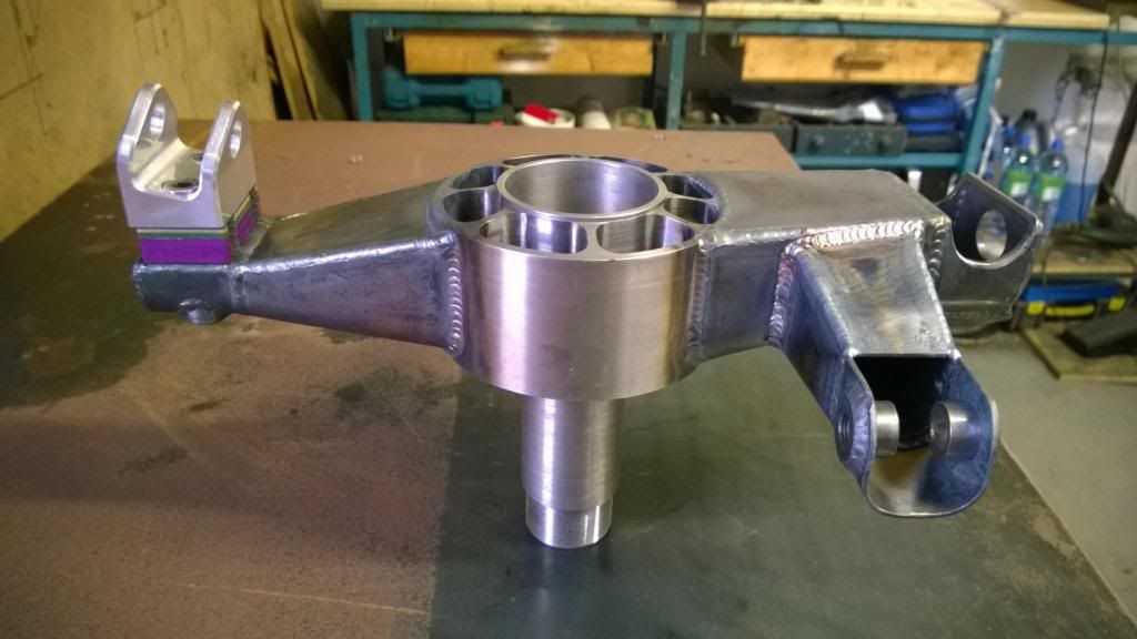
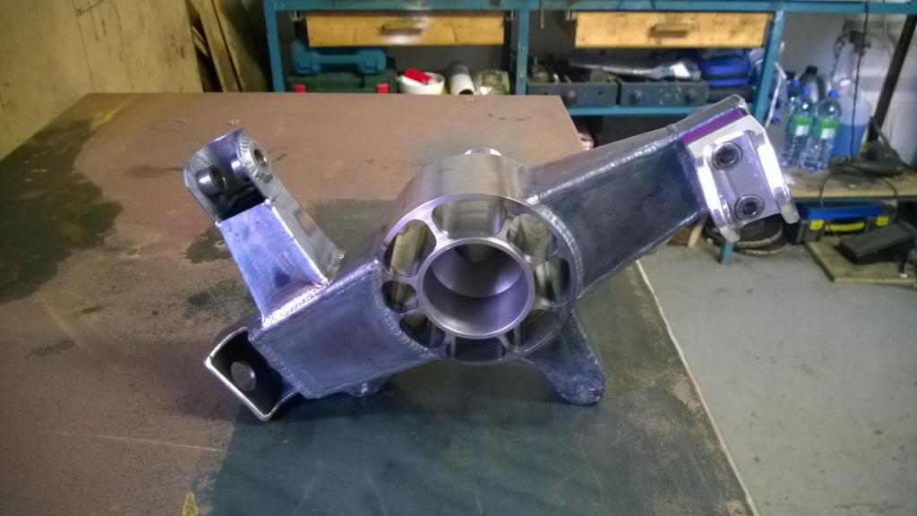
More progress on the front uprights today, and I have the main body of them done. It's late again so I'll just add pictures and a few words.
These little top caps are very fiddly!
Made a little jig for it - reversible for the other side, too.

I had to make another forming tool for these upper parts, as they have a tighter radius than the lower legs.
And then a flash of welding later.. I have a massive erection.
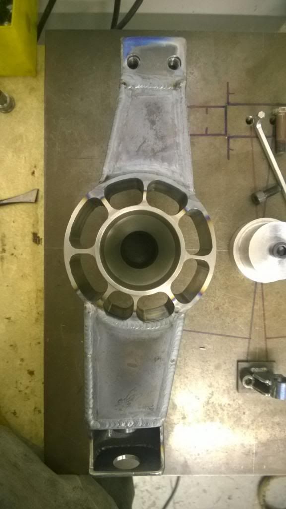
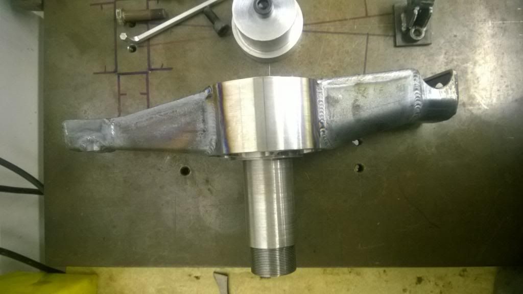
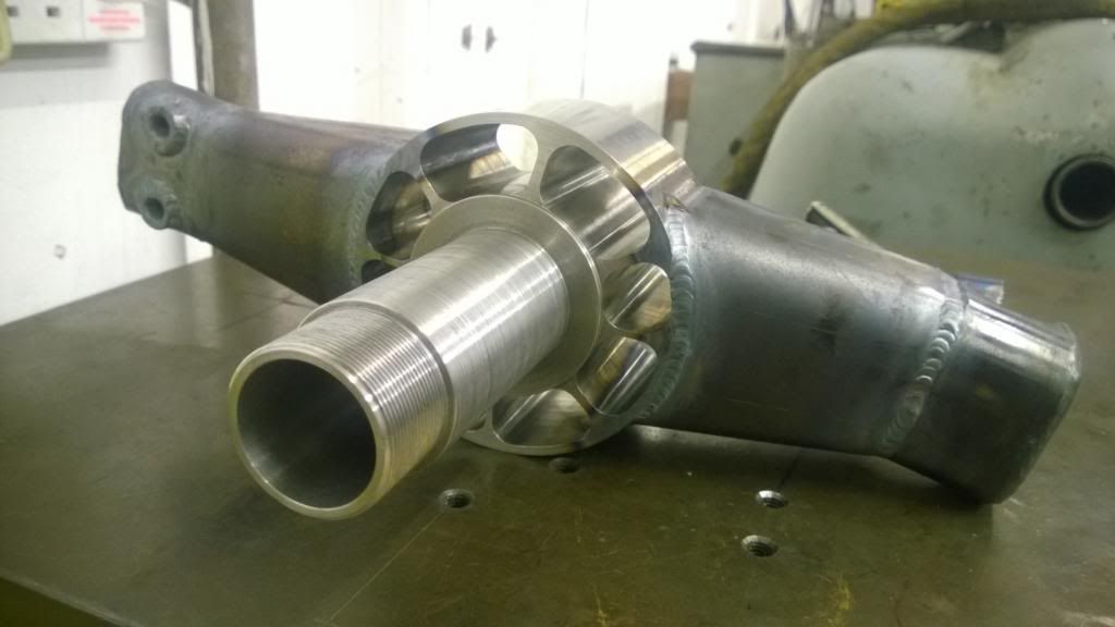

And finally some slutty weld close-ups.
So pleased with how they're coming out! I'm going to have a slow day tomorrow as I ache all over, so the next update will be at the weekend when hopefully these are finished.
More progress on the front uprights today, and I have the main body of them done. It's late again
so I'll just add pictures and a few words.These little top caps are very fiddly!
Made a little jig for it - reversible for the other side, too.
I had to make another forming tool for these upper parts, as they have a tighter radius than the lower legs.
And then a flash of welding later.. I have a massive erection.
And finally some slutty weld close-ups.
So pleased with how they're coming out! I'm going to have a slow day tomorrow as I ache all over, so the next update will be at the weekend when hopefully these are finished.
Thanks guys, glad people are enjoying the build!
I have a desk job as an engineer, but was very lucky to get my placement year with some highly skilled fabricators at BTB Exhausts, so I learnt a lot from there. It's a hobby at the moment, but I don't want to work behind a desk for the rest of my life so I figure the best way to get out of that is to get stuck in to this!
I have a desk job as an engineer, but was very lucky to get my placement year with some highly skilled fabricators at BTB Exhausts, so I learnt a lot from there. It's a hobby at the moment, but I don't want to work behind a desk for the rest of my life so I figure the best way to get out of that is to get stuck in to this!
Trtj said:
Megaflow said:
Quick question, have you done and hand calc's or FEA on the spindles in the uprights?
I ask because they look very light.
Very large diameter probably allows for this?I ask because they look very light.
Trtj said:
How the hell do you fit all this progress in around a desk job as an engineer? All I have managed in the last month is to wack a new slave cyl on my mini! Mind you having a woman in your life is a hobby ruiner 
Simple solution: no woman. I've taken this week off work, so it isn't always like this mid-week! Also helps that there is f
 k all else to do around here.
 Thanks for the kind words, chaps.
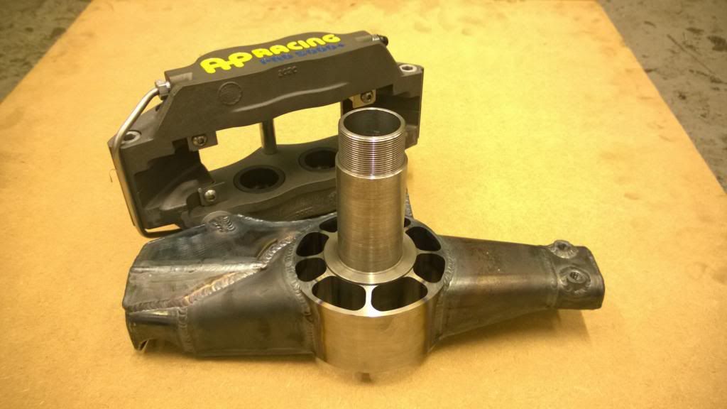
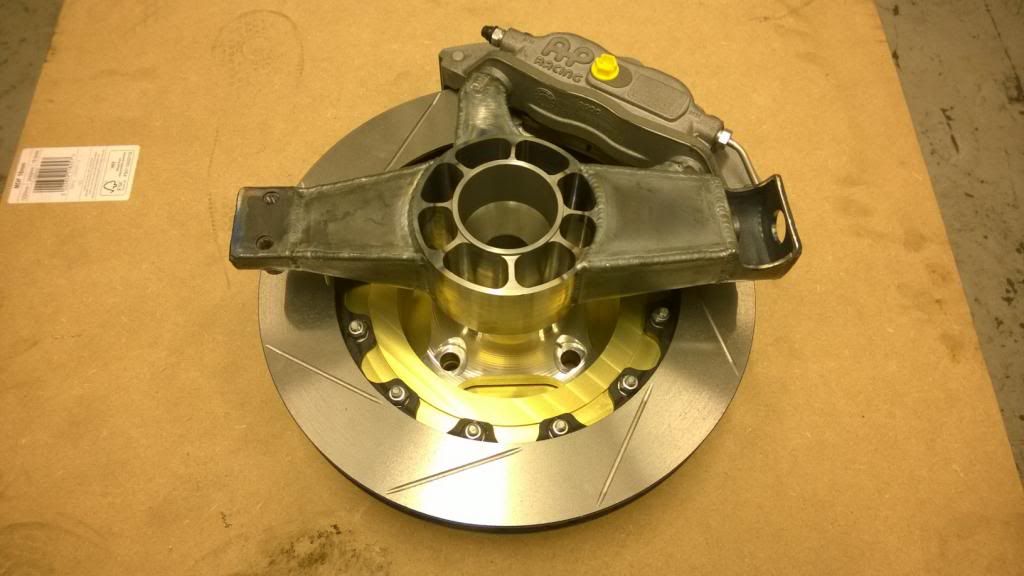
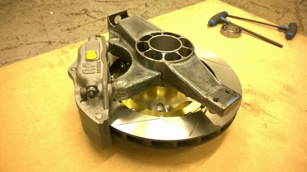
Yesterday, predictably, I was hungover. So today I tried to make up for lost time by getting on with the brake calliper mounts, and as such there is a lack of in-progress photos! Anywho.. I made a jig, then fiddled about profiling some sheet metal, then welded it all up. Behold!

I tried the caliper on..

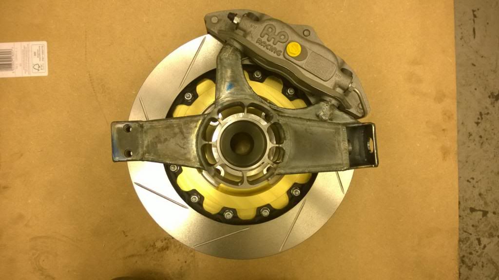
Then fitted the disc to a spare hub and checked everything fit ok. (I actually did this while it was all tacked up, but this makes a better picture!)

Now, true to routine, it's time for a very late dinner.
Yesterday, predictably, I was hungover.
So today I tried to make up for lost time by getting on with the brake calliper mounts, and as such there is a lack of in-progress photos! Anywho.. I made a jig, then fiddled about profiling some sheet metal, then welded it all up. Behold!I tried the caliper on..
Then fitted the disc to a spare hub and checked everything fit ok. (I actually did this while it was all tacked up, but this makes a better picture!)
Now, true to routine, it's time for a very late dinner.
Haha thanks, I'll be sure to keep the updates as in-depth as I can!
Aaaaaaaaaaand finished! (Or as good as..) The steering arms were quite tricky, but they look great now that they're on.

Megaflow - no weights just yet, but I will do so once they're powder coated!
So, sadly I'm back to work tomorrow.. which is a shame as I'm so close to getting the wheels on! Hopefully that will be a nice job for next weekend.
Aaaaaaaaaaand finished! (Or as good as..) The steering arms were quite tricky, but they look great now that they're on.
Megaflow - no weights just yet, but I will do so once they're powder coated!
So, sadly I'm back to work tomorrow.. which is a shame as I'm so close to getting the wheels on! Hopefully that will be a nice job for next weekend.
I'm not sure it's necessary, to be honest.. I certainly don't have the budget for it and I'd be surprised if the likes of Radical / Caterham did much more than a visual inspection of welds on top of prototype durability testing.
Since the whole car is a prototype, the durability testing on all components will be when I come to drive it. That's when I also verify my assumptions on loading (i.e. g inputs) etc, and that's about as good as you can get at this sort of level! I could test every welded part, but it would set me back years.. I think it's better just to have a sensible safety factor at the design stage.
As you said, I think pipelines / aero / civil engineering projects and the like are subject to extensive tests because of the consequences of a part failing.
I don't want this to come across the wrong way and make myself sound like a pompous tt, as I do appreciate questions, opinions, and feedback; but suspension design is my day job at an OEM and we don't even test to those extremes on commercial vans!
I have conservative enough predictions of 2g in braking / cornering and 4g in bump, and safety factors on top of that. There's no extreme customer use to be allowed for, so if I brake in to a massive pot-hole or smash a square kerb then I will expect something to get bent or broken - that's just life!
The FEA simulations I've done are pretty comprehensive, as is how I've calculated all the input forces & constraints, so I've got good confidence in them. I won't be going and immediately hammering up the hills.. as you rightly said I'll be sure to shake it down gradually and ramp up to "maximum death" after each check.
t, as I do appreciate questions, opinions, and feedback; but suspension design is my day job at an OEM and we don't even test to those extremes on commercial vans!I have conservative enough predictions of 2g in braking / cornering and 4g in bump, and safety factors on top of that. There's no extreme customer use to be allowed for, so if I brake in to a massive pot-hole or smash a square kerb then I will expect something to get bent or broken - that's just life!
The FEA simulations I've done are pretty comprehensive, as is how I've calculated all the input forces & constraints, so I've got good confidence in them. I won't be going and immediately hammering up the hills.. as you rightly said I'll be sure to shake it down gradually and ramp up to "maximum death" after each check.
Well, aside from the debate on what loading is appropriate.. measuring any displacement is going to be incredibly difficult to do reliably. The loading on an upright isn't as simple as hanging x load off at an attachment point, because the part is restrained in different degrees of freedom at each one, and then each of those has it's own load that will need to be applied in a certain direction in order to be realistic. Then you have the problem of needing a frame stiff enough to constrain it (and knowing the stiffness of that to some accuracy) then a reliable way of measuring the applied force and the displacement - the order of which are very high and very very small respectively! Once you get in to it it quickly becomes an incredibly laborious - bordering on impossible - process to try and DIY.
Anywho.. it just isn't the way things are developed these days. In an OEM you only ever run FEA prior to a part being fitted to a vehicle; there's never any "hang a few tonnes off it and see if it breaks" about it, it's all done with modelling and then validated by not breaking on the prototype vehicle.
At this level, though, the best you can do is to make sensible predictions and accurate models, and have confidence that way. Otherwise you have to spend years iterating and re-checking, or over-engineer everything outright and have an overweight car - neither of those appeal to me!
Gassing Station | Readers' Cars | Top of Page | What's New | My Stuff