Ferrari F430 Spider
Discussion


DanielSan said:
The one thing I like most of all with this whole car/thread is that you've just decided to do what YOU want to do with your car, made even better with the fact you've decided to modify and improve a Ferrari. Far too many owners of cars like this think about what the next owner will want on the car and are afraid to personalise it, 911 owners here seem to be the same. Whereas in the US for example this sort of thing is celebrated and seen as a nice bonus on a clean well looked after car.
Apology for the hijack, but all of the 911 owners I personally know have modded theirs including yours truly.Anyway, back on track. Epic work Mark.
Steering wheel – paddles - electronics
This was an interesting puzzle. I had hoped that the paddles were regular SPST switches like most others out there, but no - they aren't; the F1 switch assembly is fed by four wires but not two for each switch. The info I had was:
Pin | Function | F1 loom colour | Body loom colour
1 | S | Yellow | Grey/green
2 | - | Black | Black/white
3 | Down/- | Blue | Brown/green
4 | Up/+ | White | Blue/white
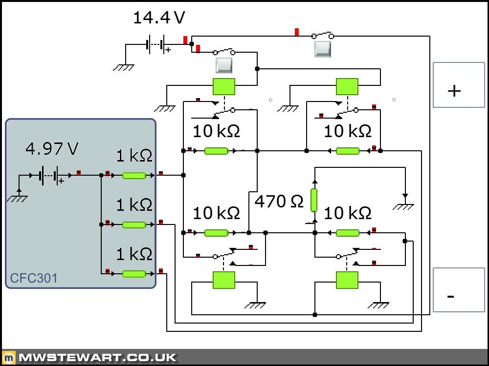
The factory diagrams are just that and don’t cover electronics. I checked the pins in the car and confirmed pin 2 was earth and the others were each 4.97v i.e. 5v which is a standard for most logic circuits. I stripped the F1 switch assembly to figure out how it worked and found that it was essentially a potential divider network that had two microswitches for each paddle. The switch pairs are pressed at the same time by each paddle. I was a bit rusty on this stuff having not touched circuits since school!
Before the advent of CAN bus it was not unusual for manufacturers to use resistor networks to transfer control signals from steering wheel to control modules elsewhere in the car when constrained by the amount of contacts available in a clock spring, but the CFC301 and even 231 were CAN based so this was something different. I modelled the F1 switch panel circuit on my computer and it was not until I tracked down a circuit diagram for an earlier TCU (all I could find) that I could actually simulate it properly: the ‘S’ contact is in fact a standby input to the TCU to reconcile inputs in the event that one of the microswitches fail. Essentially there is a voltage combination for all possible switch positions. It’s a neat little circuit.
Obviously I had to create a new circuit but I also had some design constraints:
• The Mercedes paddles are too small to modify internally for two switches;
• Adding the Scuderia CT-Off wire added between the Racing Manettino (steering wheel) and ABS module leaves two free contacts in the clock spring.
My design uses the existing terminal 15 feed already in the steering wheel for the horn and wheel module to feed the paddles, and the paddle switched outputs go back to the steering column via the two free clock spring contacts. I will use solid state DC relays to replace the function of the Ferrari microswitches. The Mercedes paddles use a much more reliable switch design than the traditional microswitch in the F1 panel so loss of the logical standby function is not a consideration.
I would like to have a custom board printed so I will draw up a PCB design and get some quotes.
Scuderia radiator cages
I’ve removed the front bumper to investigate how to fit the lower cage bars. I was pleased to find my chassis already has the necessary two Rivnuts on each side fitted, so all I need to do is grind off the weld to remove the existing bars.
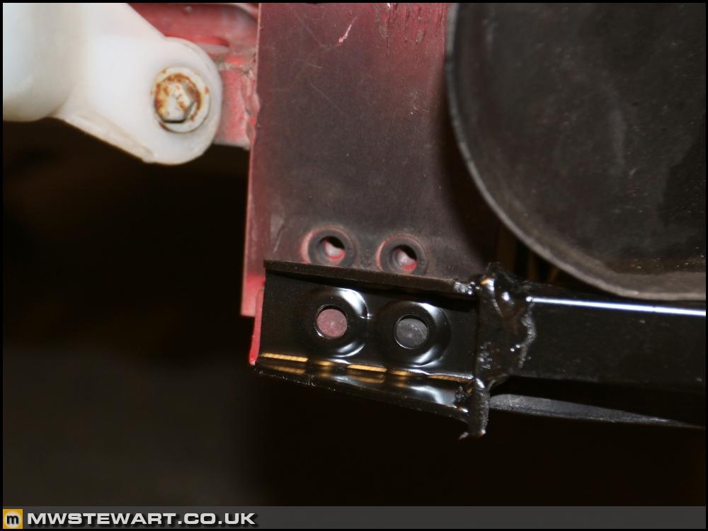
The Scuderia bars sit around 25mm higher and 25mm further forward than the F430 part.
This was an interesting puzzle. I had hoped that the paddles were regular SPST switches like most others out there, but no - they aren't; the F1 switch assembly is fed by four wires but not two for each switch. The info I had was:
Pin | Function | F1 loom colour | Body loom colour
1 | S | Yellow | Grey/green
2 | - | Black | Black/white
3 | Down/- | Blue | Brown/green
4 | Up/+ | White | Blue/white
The factory diagrams are just that and don’t cover electronics. I checked the pins in the car and confirmed pin 2 was earth and the others were each 4.97v i.e. 5v which is a standard for most logic circuits. I stripped the F1 switch assembly to figure out how it worked and found that it was essentially a potential divider network that had two microswitches for each paddle. The switch pairs are pressed at the same time by each paddle. I was a bit rusty on this stuff having not touched circuits since school!
Before the advent of CAN bus it was not unusual for manufacturers to use resistor networks to transfer control signals from steering wheel to control modules elsewhere in the car when constrained by the amount of contacts available in a clock spring, but the CFC301 and even 231 were CAN based so this was something different. I modelled the F1 switch panel circuit on my computer and it was not until I tracked down a circuit diagram for an earlier TCU (all I could find) that I could actually simulate it properly: the ‘S’ contact is in fact a standby input to the TCU to reconcile inputs in the event that one of the microswitches fail. Essentially there is a voltage combination for all possible switch positions. It’s a neat little circuit.
Obviously I had to create a new circuit but I also had some design constraints:
• The Mercedes paddles are too small to modify internally for two switches;
• Adding the Scuderia CT-Off wire added between the Racing Manettino (steering wheel) and ABS module leaves two free contacts in the clock spring.
My design uses the existing terminal 15 feed already in the steering wheel for the horn and wheel module to feed the paddles, and the paddle switched outputs go back to the steering column via the two free clock spring contacts. I will use solid state DC relays to replace the function of the Ferrari microswitches. The Mercedes paddles use a much more reliable switch design than the traditional microswitch in the F1 panel so loss of the logical standby function is not a consideration.
I would like to have a custom board printed so I will draw up a PCB design and get some quotes.
Scuderia radiator cages
I’ve removed the front bumper to investigate how to fit the lower cage bars. I was pleased to find my chassis already has the necessary two Rivnuts on each side fitted, so all I need to do is grind off the weld to remove the existing bars.
The Scuderia bars sit around 25mm higher and 25mm further forward than the F430 part.
Resistive ladders allow for signal failure detection, because there is always a voltage present on the input to the host microcontrollers ADC input pin. That means that micro can detect Off Scale High and Off Scale Low as valid fault conditions. They also allow state multiplexing into a single input
Be a little be careful about using relays to drive inputs, because they can suffer from significant contact bounce, you may want to add a low pass filter in your circuitry, although it is likely the host micro already has one as it is also reading mechanical buttons (that also can bounce)
Be a little be careful about using relays to drive inputs, because they can suffer from significant contact bounce, you may want to add a low pass filter in your circuitry, although it is likely the host micro already has one as it is also reading mechanical buttons (that also can bounce)
Max_Torque said:
Resistive ladders allow for signal failure detection, because there is always a voltage present on the input to the host microcontrollers ADC input pin. That means that micro can detect Off Scale High and Off Scale Low as valid fault conditions. They also allow state multiplexing into a single input
Be a little be careful about using relays to drive inputs, because they can suffer from significant contact bounce, you may want to add a low pass filter in your circuitry, although it is likely the host micro already has one as it is also reading mechanical buttons (that also can bounce)
Was obvs just about to say the same.Be a little be careful about using relays to drive inputs, because they can suffer from significant contact bounce, you may want to add a low pass filter in your circuitry, although it is likely the host micro already has one as it is also reading mechanical buttons (that also can bounce)
Craikeybaby said:
Resistive ladders are still used for steering wheel switches, there are some applications, such as steering wheel switches, which don't warrant having a CAN microcontroller.
Ahh OK. I didn't know that was the term for them - I worked with 'potential dividers' at school and assumed this was the same, but Googling the term has given me some more reading. Thanks.Max_Torque said:
Resistive ladders allow for signal failure detection, because there is always a voltage present on the input to the host microcontrollers ADC input pin. That means that micro can detect Off Scale High and Off Scale Low as valid fault conditions. They also allow state multiplexing into a single input
Be a little be careful about using relays to drive inputs, because they can suffer from significant contact bounce, you may want to add a low pass filter in your circuitry, although it is likely the host micro already has one as it is also reading mechanical buttons (that also can bounce)
Thanks Max. A bit more reading for me.Be a little be careful about using relays to drive inputs, because they can suffer from significant contact bounce, you may want to add a low pass filter in your circuitry, although it is likely the host micro already has one as it is also reading mechanical buttons (that also can bounce)
Lots of bits & bobs and other odd jobs consolidated into a single update.
Winter jobs cont.
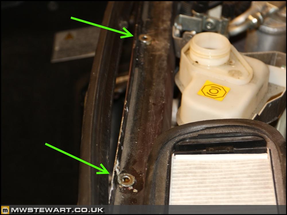
The leading edge of the scuttle panel is in a dip with a flange along the leading edge which creates a nice water trap, and on my car the mounting bolts had started to corrode inside the Rvinuts which led to them spinning when I attempted removal. I hate it when that happens! To rectify I drilled out and replaced three of the Rivnuts. At the same time I took the opportunity to inject wax into the cavities and repaint the area.
I removed the RH side skirts and again Dad kindly prepared the area for me.
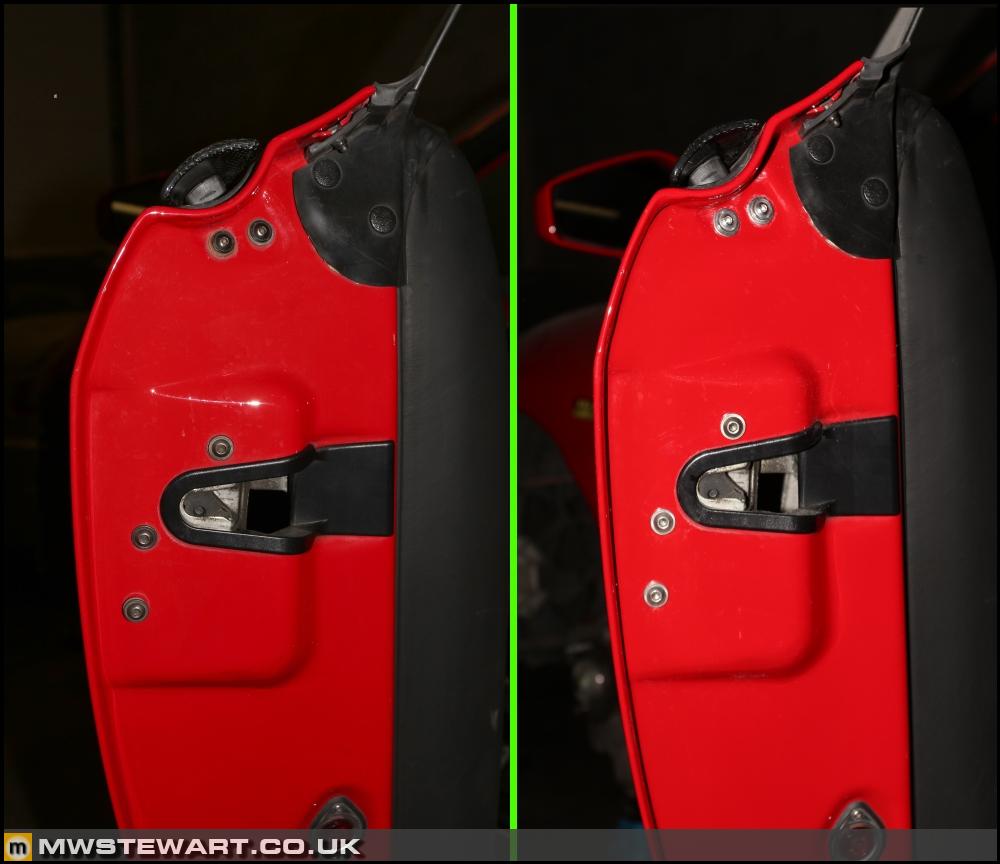
I've replaced the door strikers, their bolts (BZP grade 10.9), and the catch panel securing bolt with stainless. Ferrari revised the strikers by removing the Derlin/plastic coating and increasing the diameter of the post, I assume because the plastic always wears away, however the doors sound horrible when closing over the all-metal posts so I've gone back to the old ones!
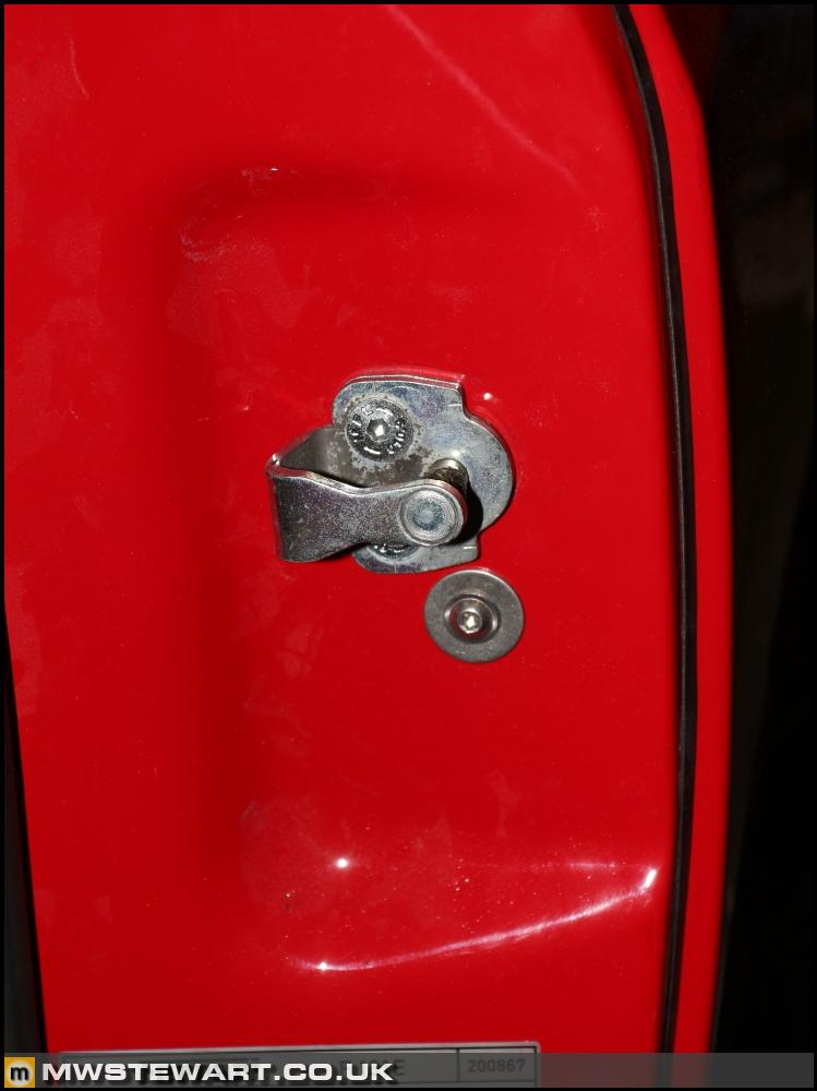
On the doors themselves I've also gone for stainless.
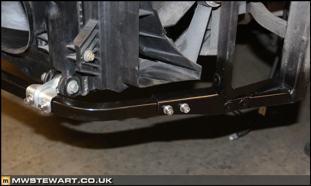
Scuderia radiator cages complete
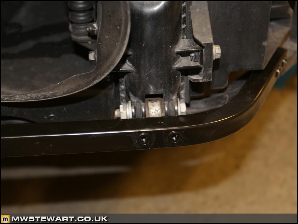
What looked to be a simple job was a bit of a pain and one of those things that was better returned to after a good nights sleep! The end of the Scuderia removable support did not align with the rest of the radiator cage and was out in horizontal and vertical planes, so to join the two I fabricated a pair of brackets from 2mm aluminium then formed the componded curves (not entirely visible in the photo) afterwards.
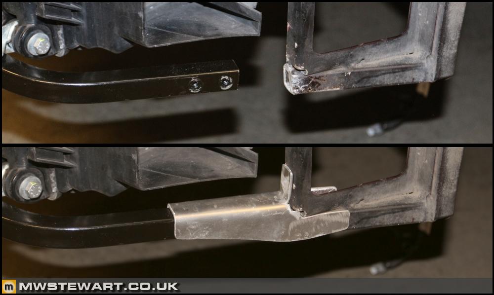
Brackets mounted and Scuderia removable sections bolted in place. Relevant areas painted satin black.
Misc
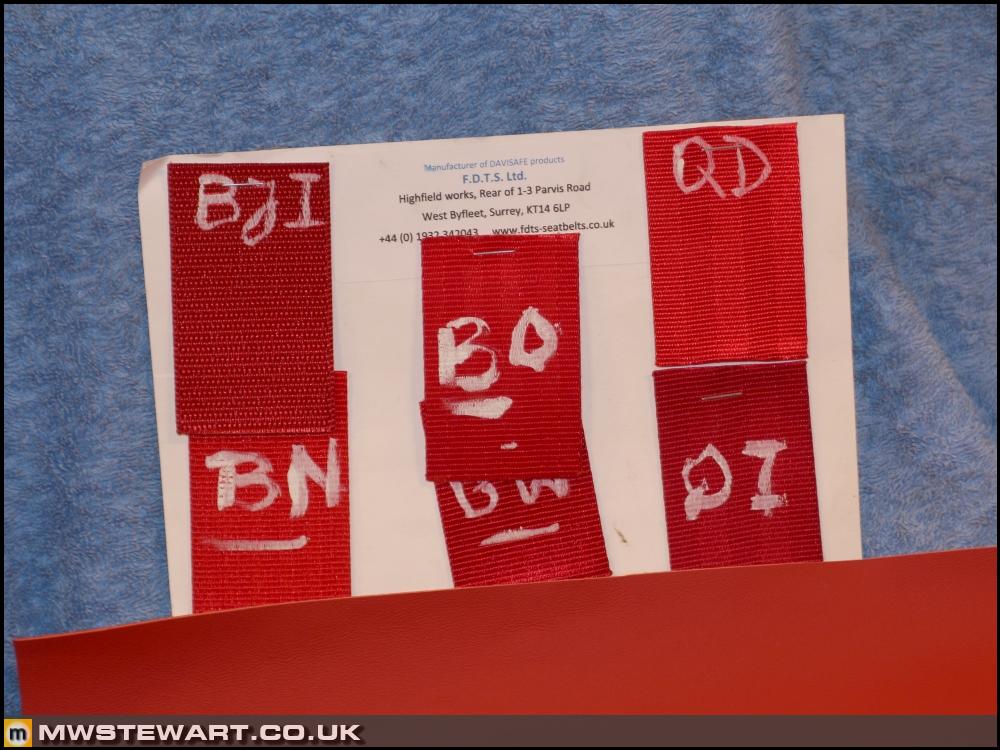
I have a sample of the red leather from my steering wheel so I've used that to choose a shade of red for the seat belts which I'll have re-webbed. I'll hold off on this for now as I want the rest of the interior in place before I make the call.
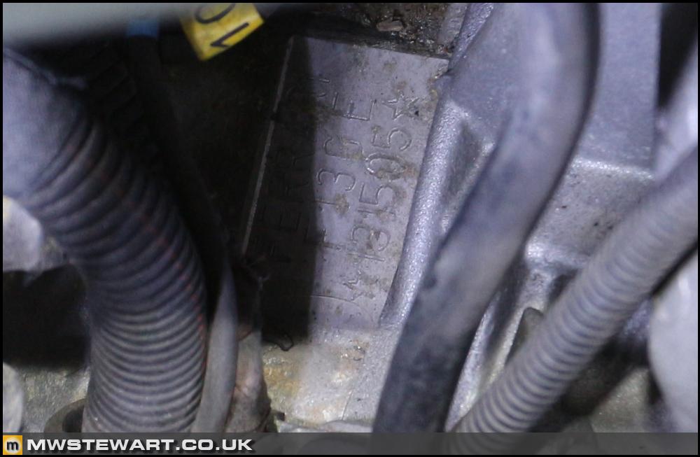
A friend is building a 9k rpm F430 engine at the moment and believes from his measurements that the cam change (from engine number 97781) was to Scuderia/Challenge spec. My engine falls well after the changeover which is good as it saves me buying new cams to have reground to Speciale spec.
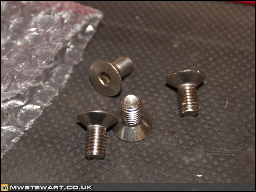
Gary from Club Scuderia who sold the Captristo system to me has kindly posted a set of locating screws to fit Challenge front CCMs to road car hubs. This means I have the option to use Challenge discs, or Challenge centres with Speciale discs. Thanks Gary.
Braking update
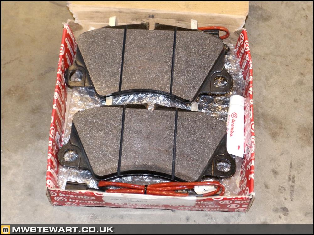
I've picked up a Speciale front pad kit. 488 pads were another option and cheaper but they aren't the 'hybrid' type just regular CCM3.
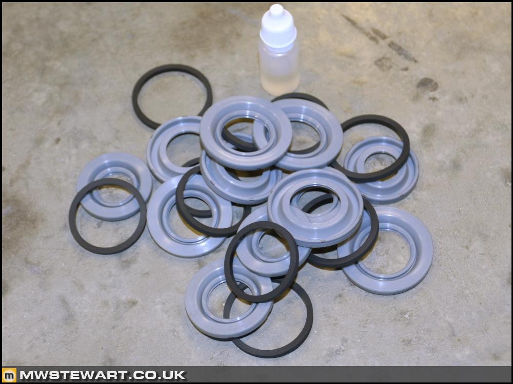
New seal kit to rebuild the Speciale calipers.
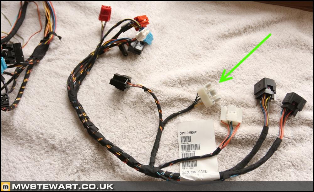
In preparation for Speciale rear calipers with integrated EPB I've taken the opportunity to modify the new Scuderia centre console loom to include an additional plug for an EPB switch. I liberated the connectors and wiring from my old F430 console loom. To maintain an OEM theme I can re-purpose another F430 roof switch - which is SPDT - and create an EPB icon for it.
When the handbrake lever is gone I will epoxy a plate over the gap in the centre console to form another storage tray, then line it with leather just like those adjacent to it.
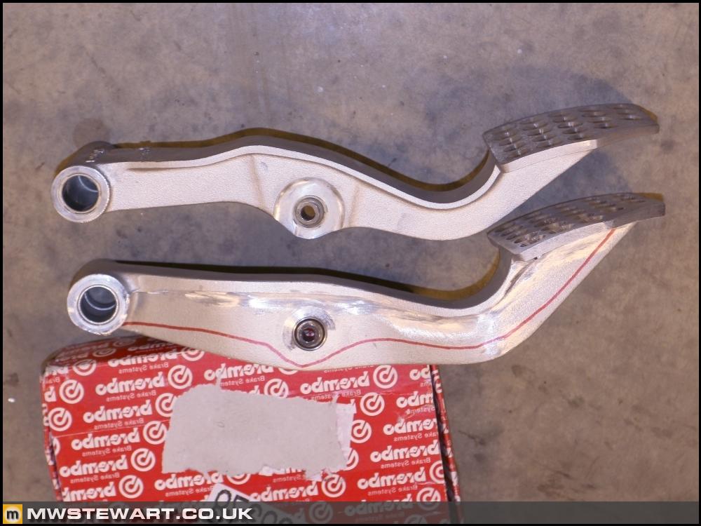
Scuderia pedals
I gave up trying to find a RHD CD/Scuderia pedal so decided to modify mine to spec. I used a 40 grit flapwheel disc in my angle grinder to remove the bumps from the pedal surface, then smoothed with 120 grit before finishing by hand. I used a 7mm drill to drill the holes and then a 16mm HSS countersink to complete the look.
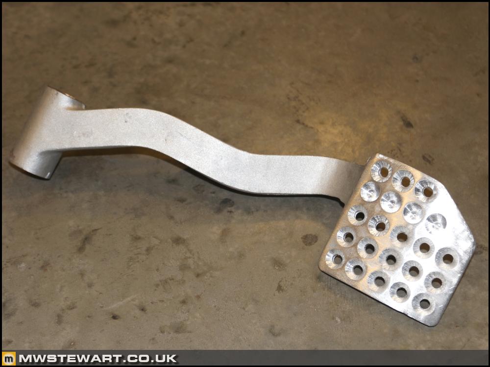
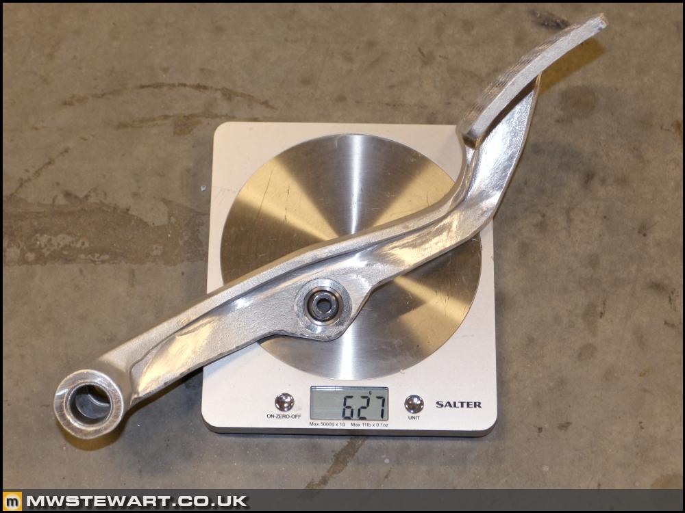
Dad also spotted that the pedal itself had been weight optimised so I chopped off the excess then finished by hand.
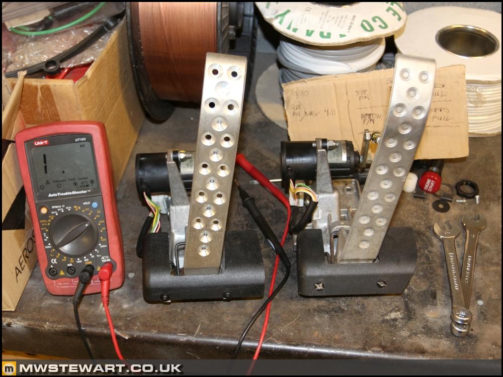
Over to the accelerator pedal, and the Scuderia part I've purchased was LHD and I found to use it in my RHD car I had to swap over the pedal to potentiometer lever rod from my old pedal. Also, this meant I had to reset the pedal stop position, so to achieve that I used a multimeter to check min/max resistance of the two pots and then adjusted the pedal stop until 1ohm away from the max travel. I did this to protect the sensor (potentiometer pair). Once the car is running I can confirm via diagnostics that the ECUs are seeing 100% requested throttle.
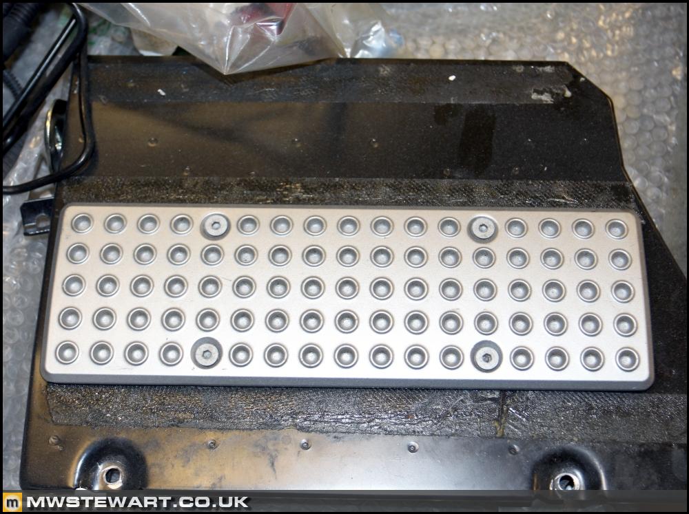
I will perform the 'Scuderia look' treatment on the passenger footrest.
Interior reassembly
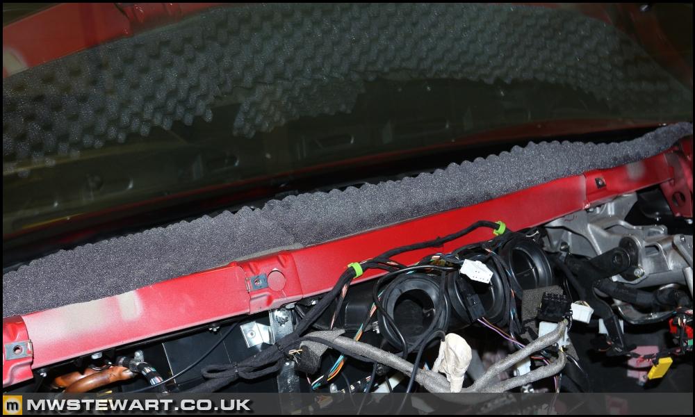
I've replaced the anti vibration foam on top of the heating ducts as it looks like the el cheapo stuff that crumbles over time. As per my other projects I use Silent Coat products.
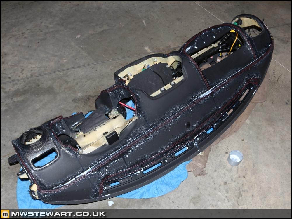
I soaked the dashboard stitching in UV protectant.
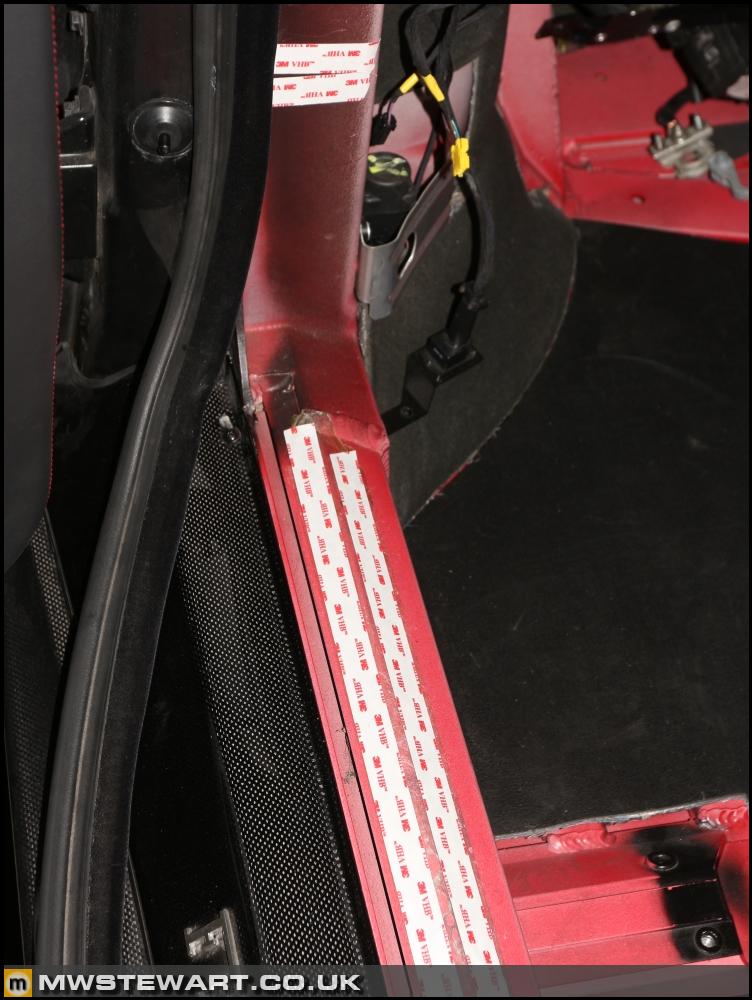
The carpets are taped down on the A pillar and sills so I've used new 3M VHB.
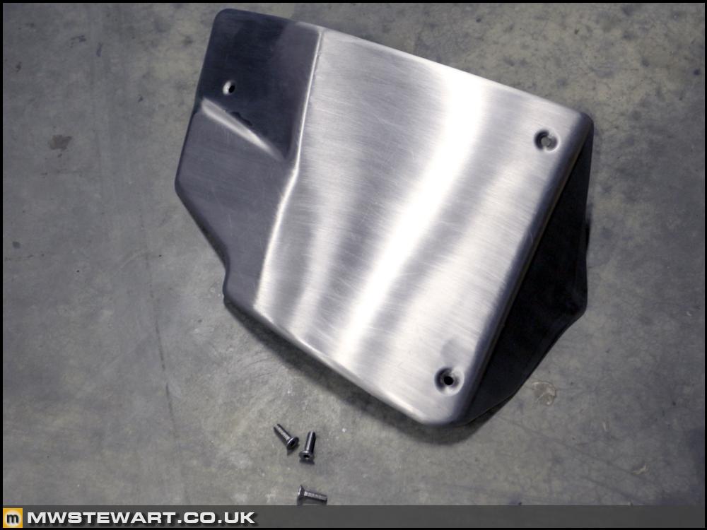
My driver's kick trim/guard had some scratches on it so I used 120 grit aluminium oxide paper in one direction to restore the brushed finish.
Carpets are in and look like new. In fairness they were were pretty good anyway.
Dashboard back in. I've taken to opportunity to improve on factory cable management because the routing for stuff like the iPod interface which is is an add on to the basic loom left just a bit of room for improvement! Also, I found the nav unit did not sit perfectly perpendicular to the dashboard so I realigned the metal frame part of the dashboard so it does. It was only a mm or two but I couldn't leave it.
Lightweight door hinges
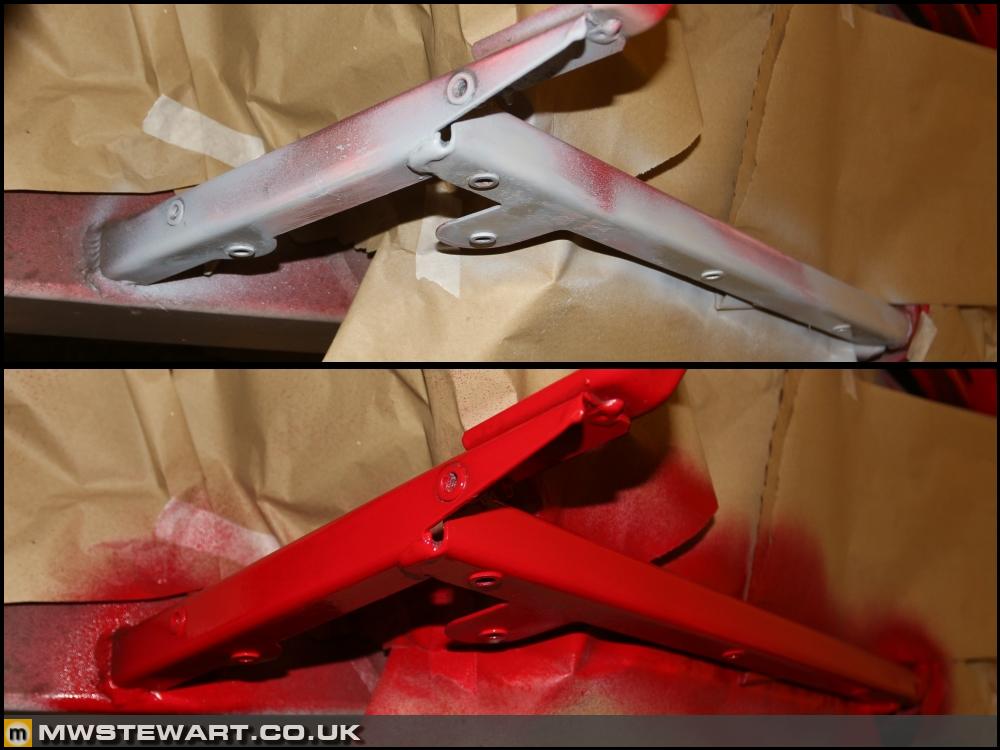
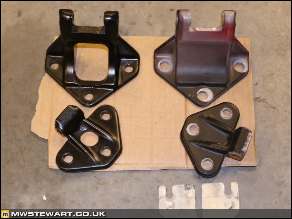
I found an F430 GT3 race team selling off some spare parts and I couldn't resist a set of door hinges they had machined to save weight. The machning work is good - I really like them - but when I picked them up the voids had been filled with expanding foam, filled over, and painted Dad kindly sorted them for me and it took him the best part of a day to get them to a standard suitable for my car.
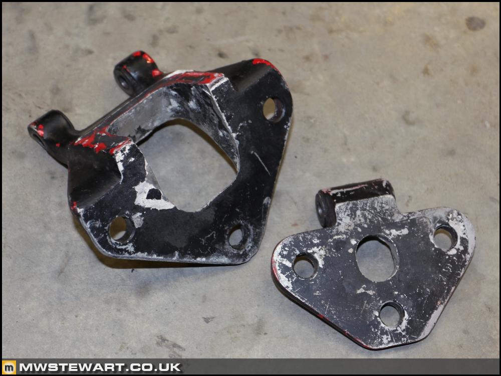
Photo to show a finished lightweight hinge (left) and an original (right). Total saving is near 1kg.
Door off for hinge fitment. I aligned the doors more evenly than they were originally and so much so that I could discard the shims that had been used at the factory. Aligning a door well takes time so using shims once it's loosely bolted to the car saves a lot of time on a production line. I only saved 20 grams a side but I just prefer the approach.
Scuderia electronics research - part 8
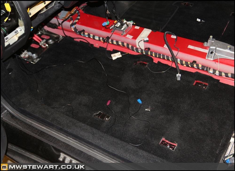
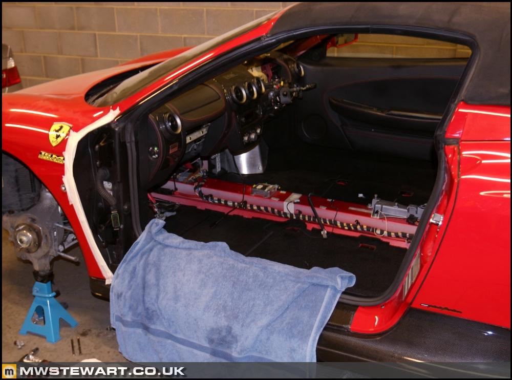
One final tidy up activity on the wiring was to remove an additional acceleration sensor (introduced with the CFC301) used by the TCU. With the advent of Superfast 2 its function had been consolidated with the digital yaw sensor. On my car the sensor was bolted to the centre tunnel.
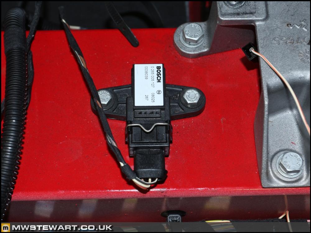
The sensor could be left connected and wired in because the Scuderia TCU does not read anything from the reference pin it is connected to, however to ensure the wiring and system was factory spec I removed the sensor and its wiring back to the TCU.
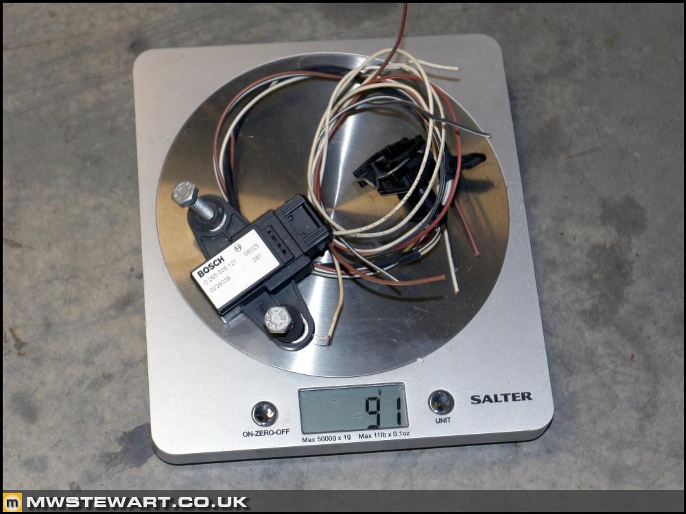
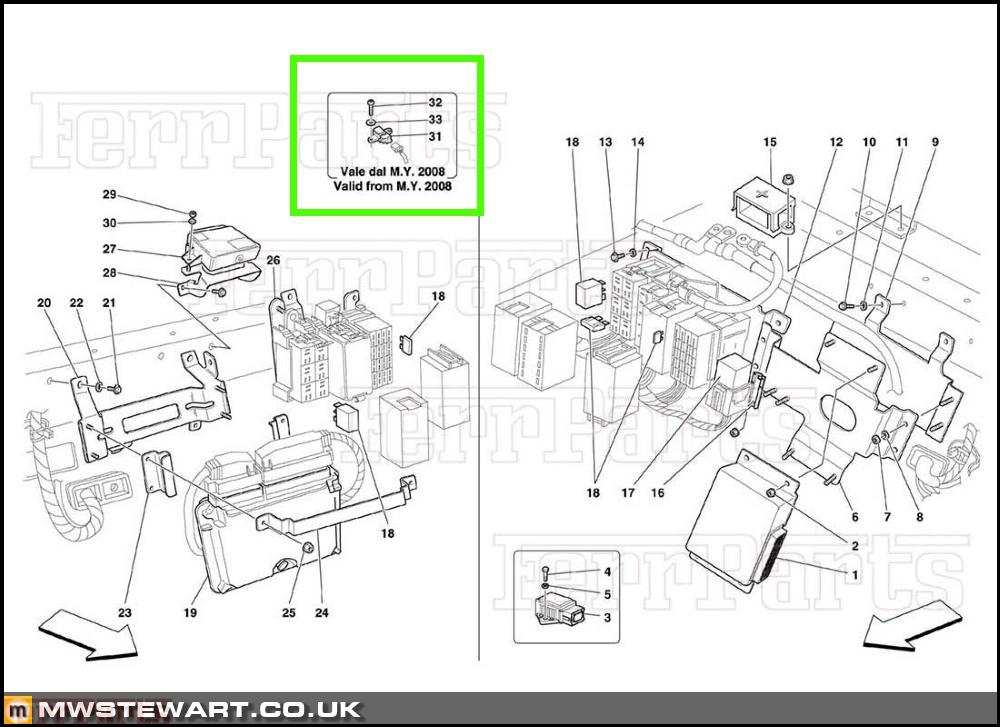
N.B. as with other MY08 parts it isn't listed on most of the online parts systems but I did find it on FerrParts.
I now also have a complete set of information on the later F1 system so I'll paste some of it below for reference.
Winter jobs cont.
The leading edge of the scuttle panel is in a dip with a flange along the leading edge which creates a nice water trap, and on my car the mounting bolts had started to corrode inside the Rvinuts which led to them spinning when I attempted removal. I hate it when that happens! To rectify I drilled out and replaced three of the Rivnuts. At the same time I took the opportunity to inject wax into the cavities and repaint the area.
I removed the RH side skirts and again Dad kindly prepared the area for me.
I've replaced the door strikers, their bolts (BZP grade 10.9), and the catch panel securing bolt with stainless. Ferrari revised the strikers by removing the Derlin/plastic coating and increasing the diameter of the post, I assume because the plastic always wears away, however the doors sound horrible when closing over the all-metal posts so I've gone back to the old ones!
On the doors themselves I've also gone for stainless.
Scuderia radiator cages complete
What looked to be a simple job was a bit of a pain and one of those things that was better returned to after a good nights sleep! The end of the Scuderia removable support did not align with the rest of the radiator cage and was out in horizontal and vertical planes, so to join the two I fabricated a pair of brackets from 2mm aluminium then formed the componded curves (not entirely visible in the photo) afterwards.
Brackets mounted and Scuderia removable sections bolted in place. Relevant areas painted satin black.
Misc
I have a sample of the red leather from my steering wheel so I've used that to choose a shade of red for the seat belts which I'll have re-webbed. I'll hold off on this for now as I want the rest of the interior in place before I make the call.
A friend is building a 9k rpm F430 engine at the moment and believes from his measurements that the cam change (from engine number 97781) was to Scuderia/Challenge spec. My engine falls well after the changeover which is good as it saves me buying new cams to have reground to Speciale spec.
Gary from Club Scuderia who sold the Captristo system to me has kindly posted a set of locating screws to fit Challenge front CCMs to road car hubs. This means I have the option to use Challenge discs, or Challenge centres with Speciale discs. Thanks Gary.
Braking update
I've picked up a Speciale front pad kit. 488 pads were another option and cheaper but they aren't the 'hybrid' type just regular CCM3.
New seal kit to rebuild the Speciale calipers.
In preparation for Speciale rear calipers with integrated EPB I've taken the opportunity to modify the new Scuderia centre console loom to include an additional plug for an EPB switch. I liberated the connectors and wiring from my old F430 console loom. To maintain an OEM theme I can re-purpose another F430 roof switch - which is SPDT - and create an EPB icon for it.
When the handbrake lever is gone I will epoxy a plate over the gap in the centre console to form another storage tray, then line it with leather just like those adjacent to it.
Scuderia pedals
I gave up trying to find a RHD CD/Scuderia pedal so decided to modify mine to spec. I used a 40 grit flapwheel disc in my angle grinder to remove the bumps from the pedal surface, then smoothed with 120 grit before finishing by hand. I used a 7mm drill to drill the holes and then a 16mm HSS countersink to complete the look.
Dad also spotted that the pedal itself had been weight optimised so I chopped off the excess then finished by hand.
Over to the accelerator pedal, and the Scuderia part I've purchased was LHD and I found to use it in my RHD car I had to swap over the pedal to potentiometer lever rod from my old pedal. Also, this meant I had to reset the pedal stop position, so to achieve that I used a multimeter to check min/max resistance of the two pots and then adjusted the pedal stop until 1ohm away from the max travel. I did this to protect the sensor (potentiometer pair). Once the car is running I can confirm via diagnostics that the ECUs are seeing 100% requested throttle.
I will perform the 'Scuderia look' treatment on the passenger footrest.
Interior reassembly
I've replaced the anti vibration foam on top of the heating ducts as it looks like the el cheapo stuff that crumbles over time. As per my other projects I use Silent Coat products.
I soaked the dashboard stitching in UV protectant.
The carpets are taped down on the A pillar and sills so I've used new 3M VHB.
My driver's kick trim/guard had some scratches on it so I used 120 grit aluminium oxide paper in one direction to restore the brushed finish.
Carpets are in and look like new. In fairness they were were pretty good anyway.
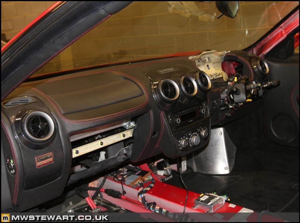
Dashboard back in. I've taken to opportunity to improve on factory cable management because the routing for stuff like the iPod interface which is is an add on to the basic loom left just a bit of room for improvement! Also, I found the nav unit did not sit perfectly perpendicular to the dashboard so I realigned the metal frame part of the dashboard so it does. It was only a mm or two but I couldn't leave it.
Lightweight door hinges
I found an F430 GT3 race team selling off some spare parts and I couldn't resist a set of door hinges they had machined to save weight. The machning work is good - I really like them - but when I picked them up the voids had been filled with expanding foam, filled over, and painted
Dad kindly sorted them for me and it took him the best part of a day to get them to a standard suitable for my car.Photo to show a finished lightweight hinge (left) and an original (right). Total saving is near 1kg.
Door off for hinge fitment. I aligned the doors more evenly than they were originally and so much so that I could discard the shims that had been used at the factory. Aligning a door well takes time so using shims once it's loosely bolted to the car saves a lot of time on a production line. I only saved 20 grams a side but I just prefer the approach.
Scuderia electronics research - part 8
One final tidy up activity on the wiring was to remove an additional acceleration sensor (introduced with the CFC301) used by the TCU. With the advent of Superfast 2 its function had been consolidated with the digital yaw sensor. On my car the sensor was bolted to the centre tunnel.
The sensor could be left connected and wired in because the Scuderia TCU does not read anything from the reference pin it is connected to, however to ensure the wiring and system was factory spec I removed the sensor and its wiring back to the TCU.
N.B. as with other MY08 parts it isn't listed on most of the online parts systems but I did find it on FerrParts.
I now also have a complete set of information on the later F1 system so I'll paste some of it below for reference.
Ferrari said:
• PRE-SOFAST and SOFAST transmission control system (CFC201): this is the first generation of transmission control system as introduced in 1999 on the 360 model. The name SOFAST (soft + fast) was introduced little later when a new control software was applied with the aim to enhance operating comfort. Management of gearchanges is not influenced by information concerning vehicle dynamics.
• SOFAST II transmission control system (CFC231): a new control unit with new software was introduced to optimise gearchange comfort and reduce noise levels. An improved operating management of the clutch was obtained by the introduction of the Kisspoint self-learning procedure. Management of gearchanges is not influenced by information concerning vehicle dynamics.
• SOFAST III transmission control system (CFC301): the introduction of Sofast III involves a new control unit and the introduction of a longitudinal acceleration sensor and a clutch pressure sensor. The longitudinal acceleration information allows a gearchange and clutch management influenced by vehicle dynamics. The clutch pressure information allows the ECU to calibrate the clutch diaphragm spring characteristic. These modifications resulted in a much improved clutch management.
• SOFAST III+ transmission control system (CFC301): identical to SOFAST III but with modified clutch and new operating software for further improved clutch management.
• SOFAST IV with Superfast shift transmission control system (CFC301): new operating software and various hardware modifications are applied. The introduction of the Superfast shift gearshift operating strategy reduces gearshift times to 100 ms.
• SOFAST IV with Superfast shift 2 transmission control system (CFC301): new operating software and various hardware modifications are applied. The introduction of the Superfast shift 2 gearshift operating strategy further reduces gearshift times to 60 ms.
Hydraulic pressure sensor on clutch housing (Sofast III onward)
An analogue pressure sensor measures the hydraulic pressure in the clutch actuator, which is in direct relation to the application force of the diaphragm spring. By this way the exact clutch characteristic can be identified. This component is installed starting from sofast III.
Longitudinal acceleration sensor (Sofast III)
A longitudinal acceleration sensor was introduced on the Sofast III system to allow to calculate the road gradient (flat surface, uphill, downhill). This information is used by the NCR (TCU) to adapt the clutch activation during driving away and the gearshift strategy in automatic driving mode in base of the road gradient. Starting from assembly 24275, the sensor has been dropped and longitudinal acceleration information is received from the ABS / ESP system (NFR) over the C-CAN line.
Specific components for Sofast 4 with Superfast shift
• Reinforced gearbox housing (new differential lid)
• Reinforced, three-pad gearshift forks made of a new material
• New clutch “Ribbed finger” (PIS value still 4,2mm – 327 bit)
• New clutch housing with double support bearing
• New electric pump with increased capacity and air conveyor
• Clutch position sensor with improved thermal isolation for wiring
• New hydraulic circuit oil: Shell Donax TX (0,5L)
• Direct connection between NCR (pin 80 CFC301) and NCM (pin 81 Motronic ME7.1.1) for engine cut-off in Superfast shift mode: When Superfast shift mode is active, the fuel cut-off command during gearshift to the engine control system is not given over the C-CAN line but by a direct connection by an “active low” signal. This allows a faster command and improved synchronisation between gearbox control and engine control during gearshift phase.
• Note: in case of failure of the line (interruption, short circuit) a specific error code will be stored (DTC P1761) and the Superfast shift mode will be disabled.
• Activation of reverse lights via CAN: pin 41 of the CFC301 unit is no longer used to operate the reverse lights relay. Instead, it operates the LED behind the Reverse button on the control panel located on the central console.
Specific components for Sofast 4 with Superfast shift 2 (CV2) (60ms)
Sofast 4 with Superfast shift 2 gearshift strategy is an evolution of the Sofast 4 with Superfast shift system (100MS) as used on the 599 GTB model. The only hardware modification regards the gearshift finger in the hydraulic actuator: in order to further reduce the needed time for a gearshift operation it was necessary to develop a system that does not require a centering in the neutral position during the gearshifting.
This system involves removing the engagement actuator tappets and increasing the lever/fork clearance, consequently increasing the actuator stroke by 2mm. Simplification of the system, thanks to the elimination of the centering tappets and relative seals, use of a piston shaft with only one seal, reduced machining work on the engagement shaft due to the elimination of the sealing seats.
The actuator interface components have been redefined:
• Gearshift finger
• Latch and relative drive bushings
The following internal components of the hydraulic actuator have been modified:
• Engagement piston sleeve
• Engagement shaft
• Selection movement lobe


Gassing Station | Readers' Cars | Top of Page | What's New | My Stuff