Attempting to build the fastest road legal Elan in the world
Discussion


I am a little surprised that All That Jazz hasn't made any comments on here. He was instrumental in me starting this thread by showing me how to do a search for what turned out to be a non-existent build thread .
http://www.pistonheads.com/gassing/topic.asp?h=0&a...
http://www.pistonheads.com/gassing/topic.asp?h=0&a...
Edited by stevebroad on Monday 2nd January 18:32
You might want to log your fuel temps on longer running events.
Any particular reason for 8 injectors? I prefer the safety of 4. With 8 if one drops out you run lean. Yes you can have inbuilt safety strategies in your ecu but can possibly be too late.
Have you mentioned what ecu you are using?
Any particular reason for 8 injectors? I prefer the safety of 4. With 8 if one drops out you run lean. Yes you can have inbuilt safety strategies in your ecu but can possibly be too late.
Have you mentioned what ecu you are using?
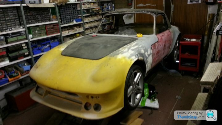
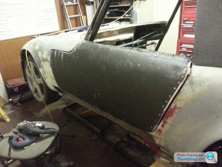
All that is left to show is the bodywork and we are up to date.
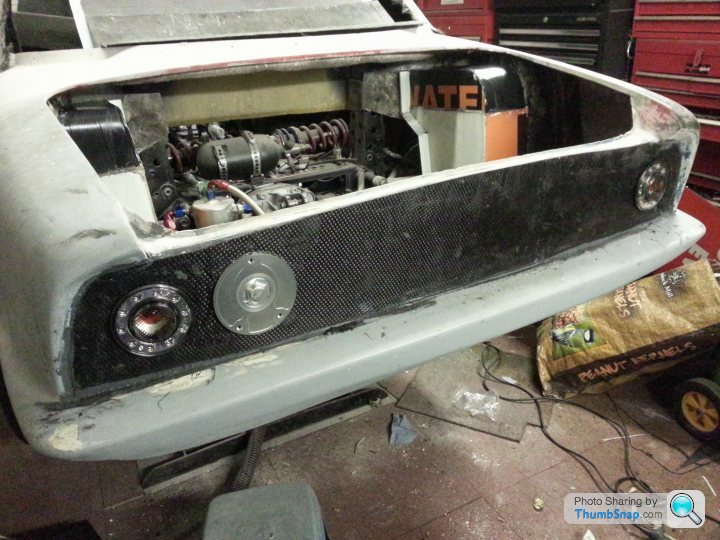
Front is a work in progress. The centre bottom opening will be closed due to too much air getting to the radiator/intercooler chamber. The two circular holes on the right will also be filled in as there isn't now going to be an oil cooler behind them.
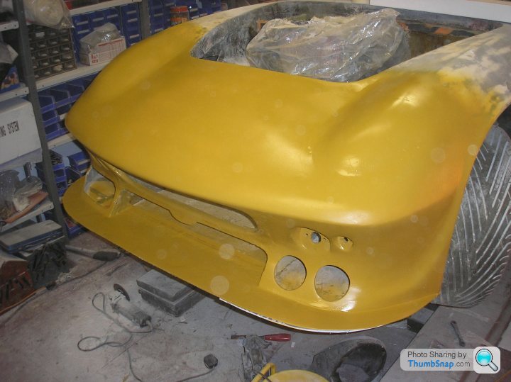
Likewise the three round holes on the left. Again, too much air getting in, this time to the air filter chamber.
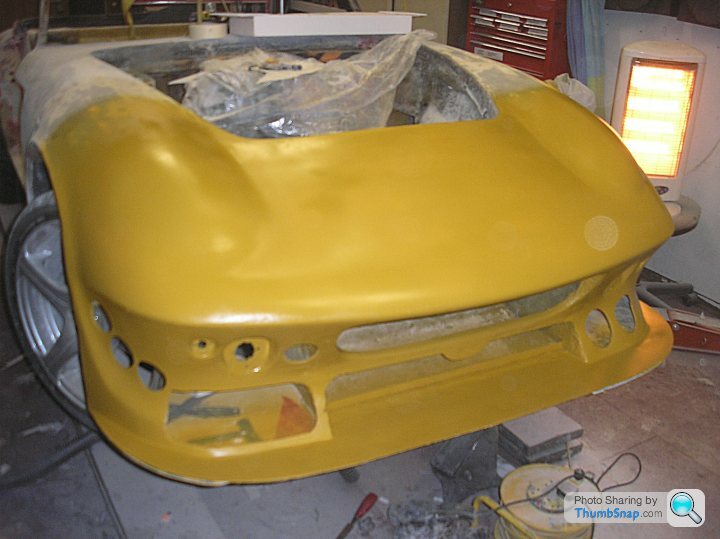
Bonnet and boot are carbon fibre.
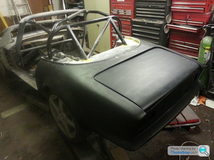
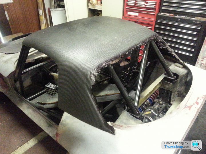
Likewise the roof, which is also a work in progress.
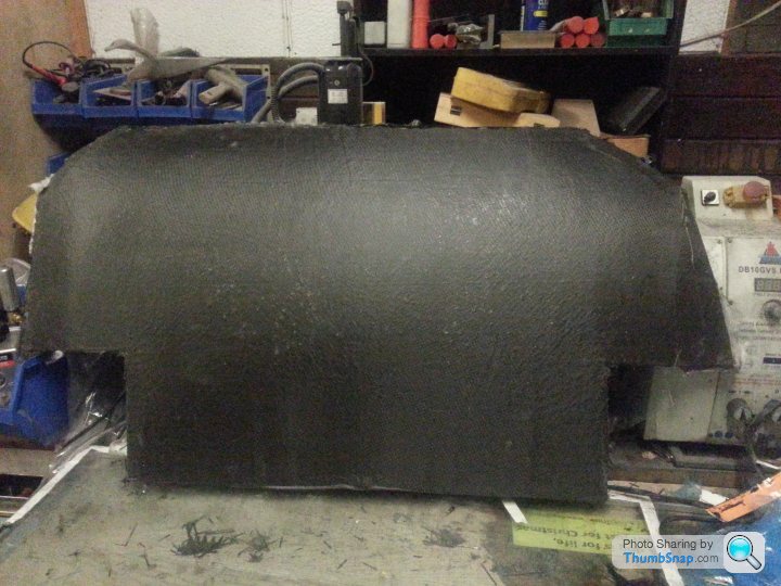
The boot floor
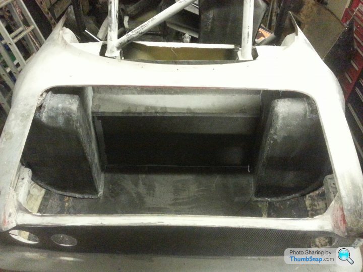
Rear wheel tubs and bulkhead/firewall
Front is a work in progress. The centre bottom opening will be closed due to too much air getting to the radiator/intercooler chamber. The two circular holes on the right will also be filled in as there isn't now going to be an oil cooler behind them.
Likewise the three round holes on the left. Again, too much air getting in, this time to the air filter chamber.
Bonnet and boot are carbon fibre.
Likewise the roof, which is also a work in progress.
The boot floor
Rear wheel tubs and bulkhead/firewall
Edited by stevebroad on Monday 2nd January 21:25
jontysafe said:
You might want to log your fuel temps on longer running events.
Any particular reason for 8 injectors? I prefer the safety of 4. With 8 if one drops out you run lean. Yes you can have inbuilt safety strategies in your ecu but can possibly be too late.
Have you mentioned what ecu you are using?
Unlikely to be doing any long events as drag racing is my main goal.Any particular reason for 8 injectors? I prefer the safety of 4. With 8 if one drops out you run lean. Yes you can have inbuilt safety strategies in your ecu but can possibly be too late.
Have you mentioned what ecu you are using?
Engine was built some 12 years ago when decent large volume injectors weren't available. Different story now but I will stick with these for now as I just want to get it running. Tweaks such as injector changes can wait until then :-)
Life F88.
More carbon fibre bits
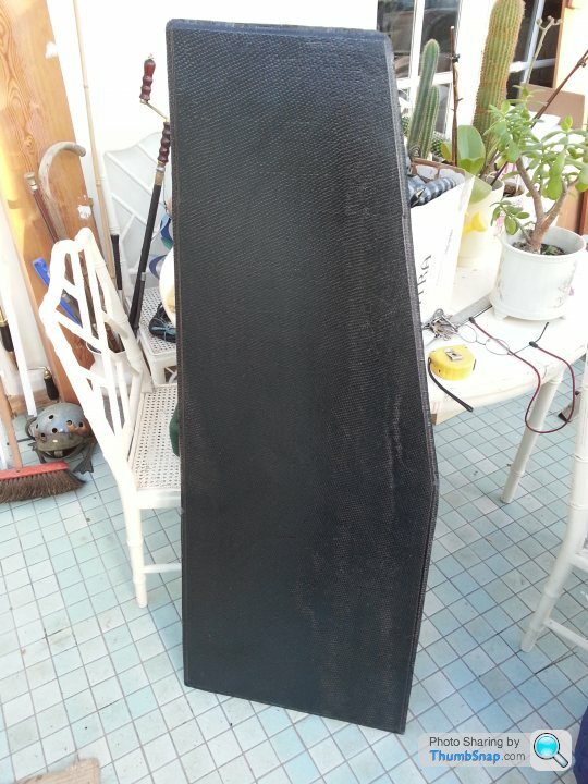
Door skins
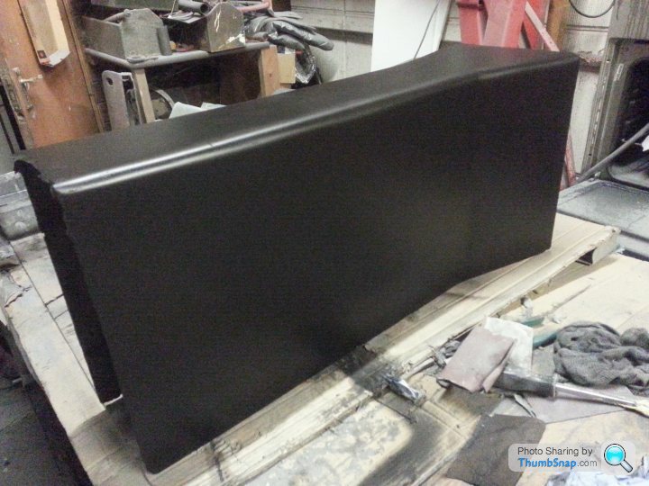
Rear panel. Original 1kg, new CF panel 400gms
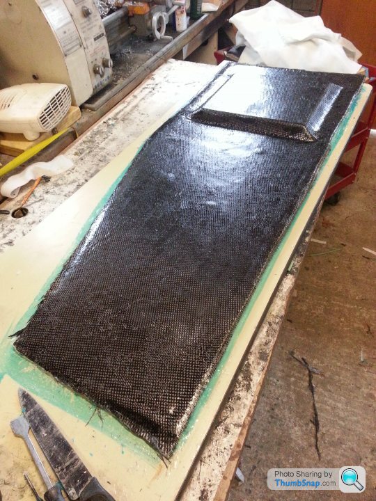
Passenger floor. 2 layers of carbon, 3mm foam core then 2 more layers of carbon. Orignal fibregalss floor panel 5kg, CF panel 2kg
Driver's floor. Recess is to allow the seat to be set lower so that I clear the roll cage.
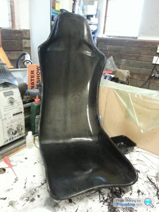
Seats. Driver's seat 2.4kg (Reverie), passenger's seat 900gms (home made)
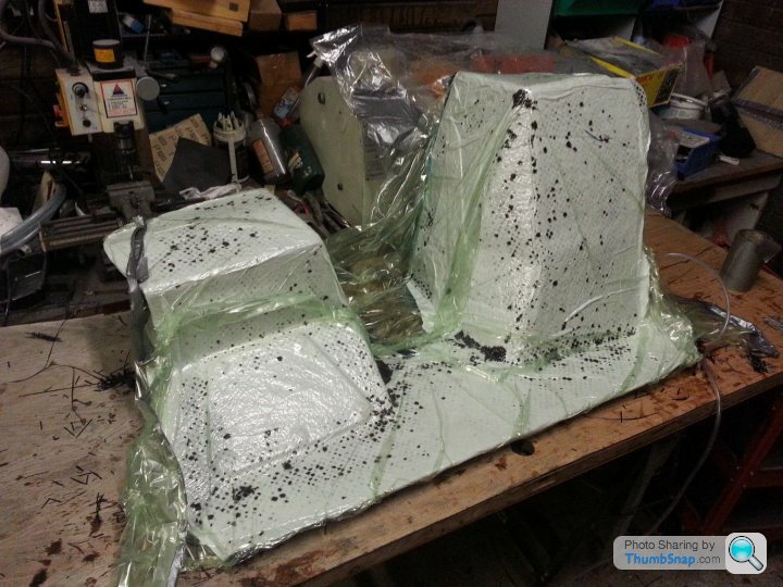
Preparing mould
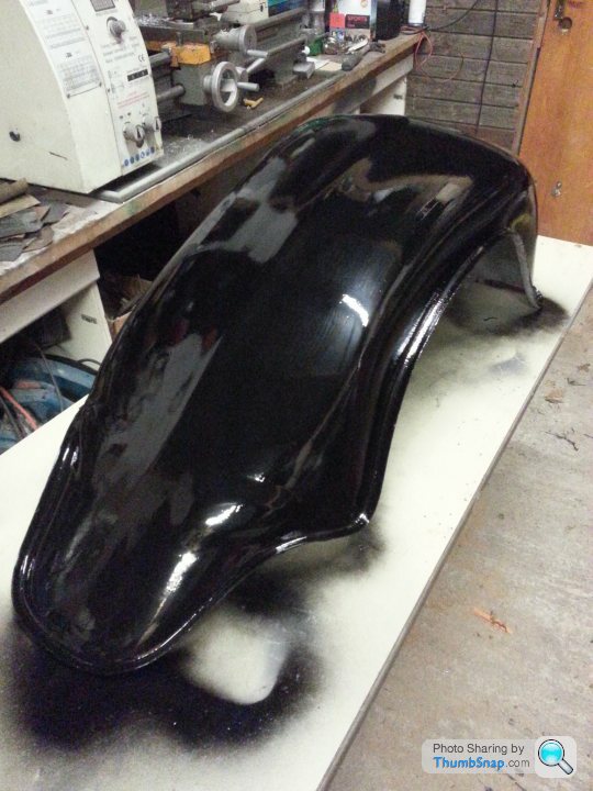
Starting vacuum curing process
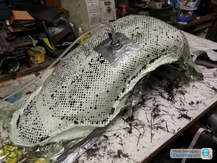
After a couple of hours
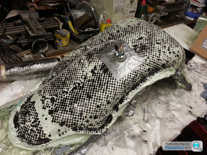
30 hours later removed from bagging materials
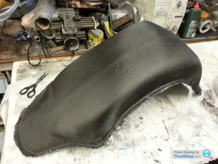
Pulled from mould. Not bad for a beginner. As I will be painting all the carbon I am not bothered about finish (just as well, really). The circle was caused by the vacuum connector. A lesson learned.
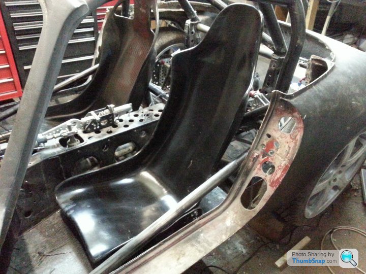
Seats fitted. Closest one is the one I made. It has still to be rubbed down and painted (this will hide the imperfections)
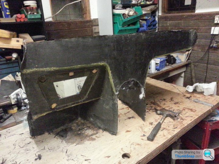
Dash and centre console.
The Dash unit includes all the footwell panelling.
Design fabricated out of Corex plastic board.
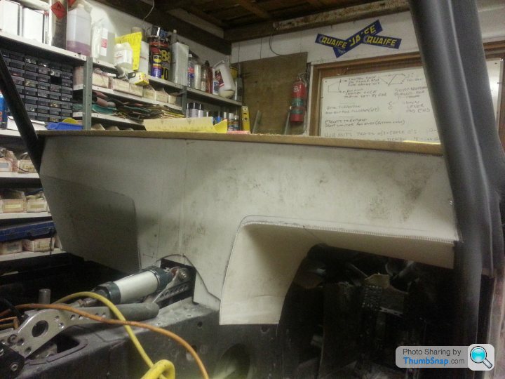
This was then covered in fibreglass
Fibreglass mould covered with two layers of carbon then vacuum bagged for 30 hours
Dash removed from mould
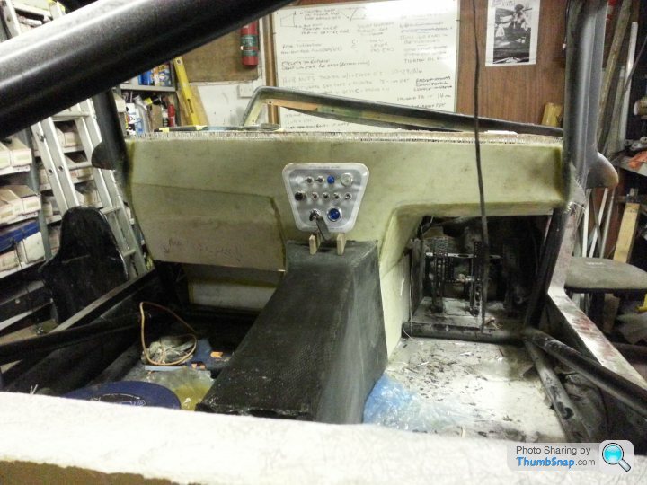
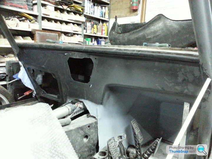
In process of being fitted. The dash top and centre console made the same way but with MDF in place of Corex.
Centre console
Rear panels
Moulds
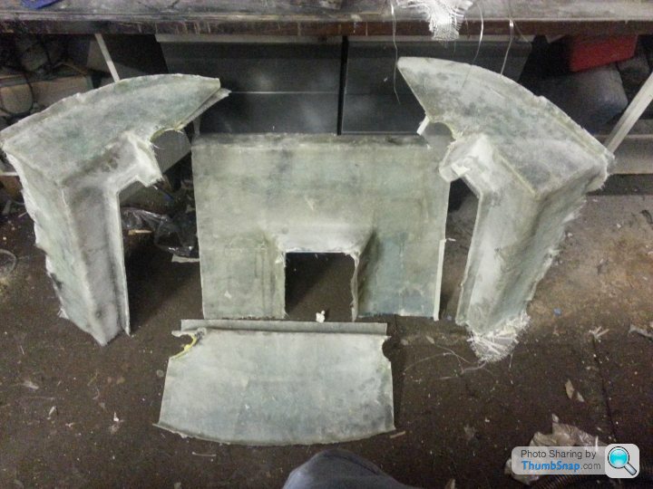
Some of the panels ready to be fitted
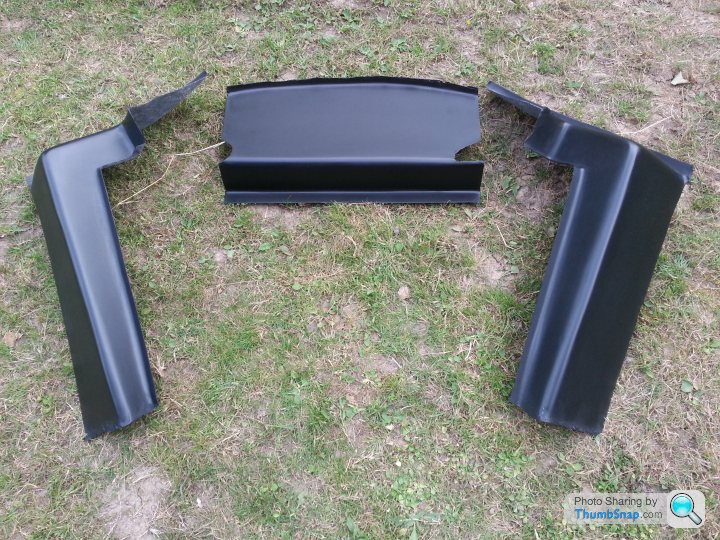
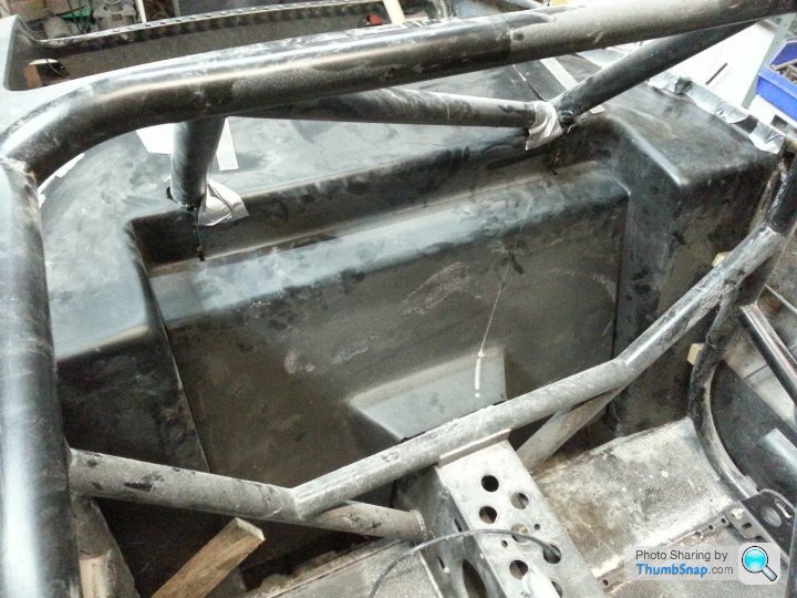
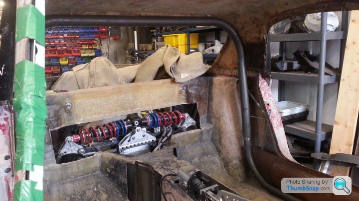
Glued in place, but a lot of tidying up to be done (filling in around cage and hiding panel joints, etc). Centre panel is removable to allow access to suspension
Door skins
Rear panel. Original 1kg, new CF panel 400gms
Passenger floor. 2 layers of carbon, 3mm foam core then 2 more layers of carbon. Orignal fibregalss floor panel 5kg, CF panel 2kg
Driver's floor. Recess is to allow the seat to be set lower so that I clear the roll cage.
Seats. Driver's seat 2.4kg (Reverie), passenger's seat 900gms (home made)
Preparing mould
Starting vacuum curing process
After a couple of hours
30 hours later removed from bagging materials
Pulled from mould. Not bad for a beginner. As I will be painting all the carbon I am not bothered about finish (just as well, really). The circle was caused by the vacuum connector. A lesson learned.
Seats fitted. Closest one is the one I made. It has still to be rubbed down and painted (this will hide the imperfections)
Dash and centre console.
The Dash unit includes all the footwell panelling.
Design fabricated out of Corex plastic board.
This was then covered in fibreglass
Fibreglass mould covered with two layers of carbon then vacuum bagged for 30 hours
Dash removed from mould
In process of being fitted. The dash top and centre console made the same way but with MDF in place of Corex.
Centre console
Rear panels
Moulds
Some of the panels ready to be fitted
Glued in place, but a lot of tidying up to be done (filling in around cage and hiding panel joints, etc). Centre panel is removable to allow access to suspension
Edited by stevebroad on Tuesday 3rd January 18:44
Edited by stevebroad on Tuesday 3rd January 18:54
Loving your work on this....
BTW, are/were you aware of the Elan drag racer Palladin ?
http://www.pistonheads.com/gassing/topic.asp?t=129...
BTW, are/were you aware of the Elan drag racer Palladin ?
http://www.pistonheads.com/gassing/topic.asp?t=129...
Turn7 said:
Loving your work on this....
BTW, are/were you aware of the Elan drag racer Palladin ?
http://www.pistonheads.com/gassing/topic.asp?t=129...
ThanksBTW, are/were you aware of the Elan drag racer Palladin ?
http://www.pistonheads.com/gassing/topic.asp?t=129...
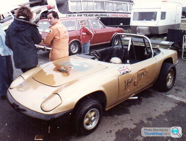
Yes. Also, I took this photo of his brother, Keith, leaning on Hay Jude many years ago.
Bdevo3 said:
Love seeing diy threads like this. Is the carbon fibre tricky to work with
Thanks.No, if you have experience with fibreglass you can use carbon fibre.
It is similar to working with woven fibreglass rather than the chopped mat variety, the main differences being it is less pliable and frays like crazy. The biggest difference, however, is in the resin curing time. Fibreglass resin cures in minutes whereas the epoxy resin used with carbon takes hours, sometimes days.
Roll Cage.
A full roll cage wasn't in my plans. Too bloody heavy. I planned to fit a hoop.
I got as far as a first fit before we decided to check how twisty the chassis actually was. It had been strengthened above and beyond the 26R racing Elan spec so I thought that it would be fine. However, it turned out to be like a stick licorice. Well,not that bad, it would have been more than adequate for 200-250bhp but no good for more than double that.
So a rethink was in order. I looked into stiffening using carbon fibre as an extra skin. This would have worked, possibly, but it would have been difficult with no guarantee of success. In the end I had to concede that the right way to go was full roll cage. I hated the thought of all that extra weight but consoled myself with the fact that without it I wasn't going to go fast. The added bonus was that I would be a lot safer.
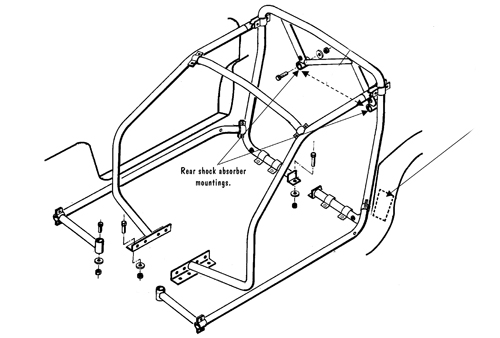
Next step then was to get a cage, or so I thought. It quickly dawned on me that there was only one cage commercially available for the Elan, one made by Safety Devices. However, a quick look at this convinced me that it was not suitable for my purpose. It would save you in a crash but doesn't add much to the torsional stiffness of the chassis.
The only solution was to design my own. There followed quite few evenings downloading every photo I could find of Elans with roll cages. Although there was nothing that exactly meet my criteria they gave me ideas and a design slowly formed in my head. However, when I started to discuss my plans with my fabricator and Graham from Graham Hatherway Racing, a better design evolved.
Next step was to buy the steel. As I didn't much like the idea of filling the car with heavy steel I decided to use T45 seamless tube. Although it is the same weight size for size as normal cage steel it is much stronger so a thinner wall can be used and still have a stronger cage. The only down side is the cost. The tube cost me £750 but saved 13kg.
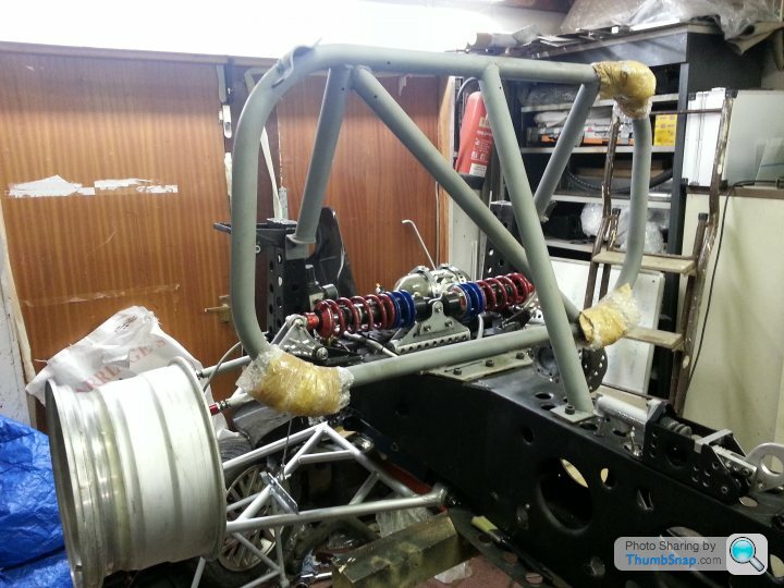
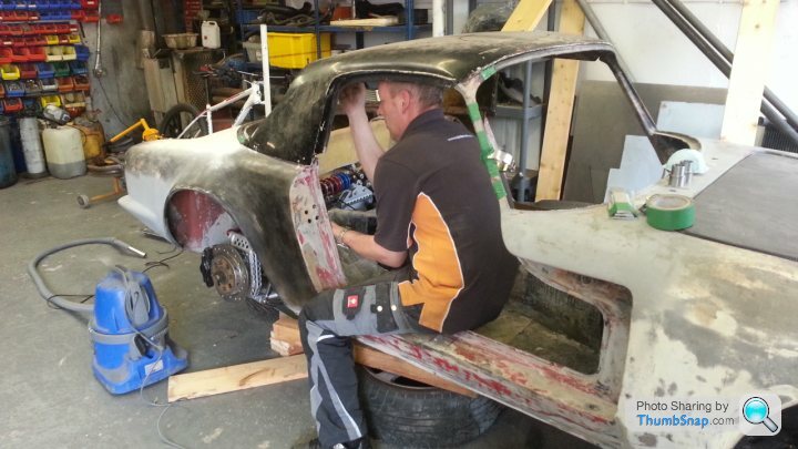
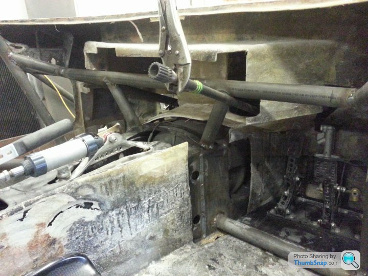
The car and tube was delivered to Martin at Graham's shop and the chassis leveled. We then spent a couple of days crawling over the car refining the design. The big problem is that you can't weld to fibreglass and I was out of sky hooks so we had to devise a cage (so it evolved again) that didn't need to be fixed to the floor, so it was effectively a space frame. It was nearly four days before we actually cut our first tube and the whole job took four weeks and more changes were made as the build progressed (for example, the initial plan didn't allow for tubes through the firewall into the engine bay, connecting to the chassis close to the front suspension uprights.
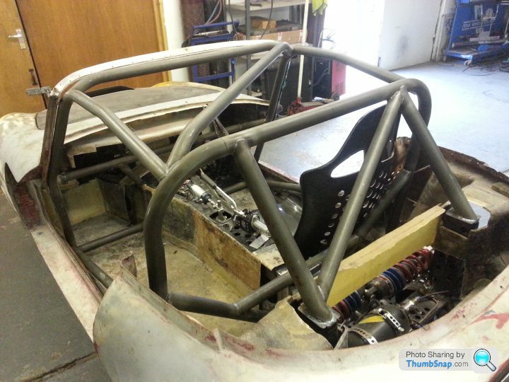
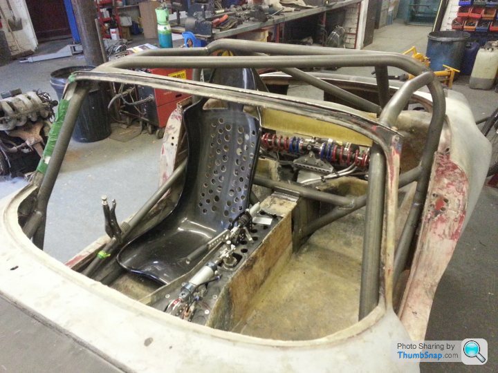
Because of the small cabin, we spent a lot of time getting the cage to fit as snugly as possible to the cabin sides. I think we did a pretty good job in this respect.
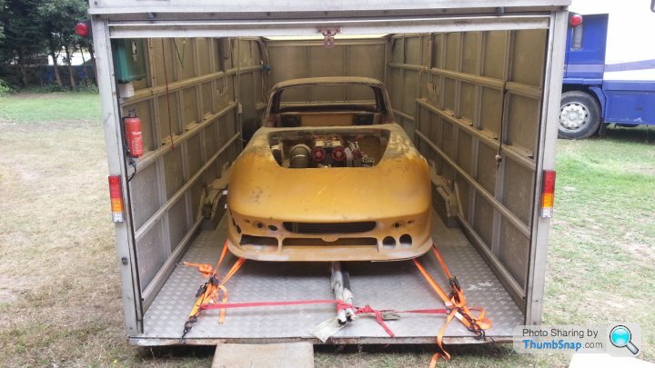
Ready for the off. Notice tube strapped down under the car.
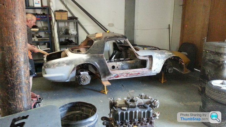
Car being set up
Martin with the first section, always the most difficult piece as everything else is related to this bit.
First section in place
Rear section tacked together.
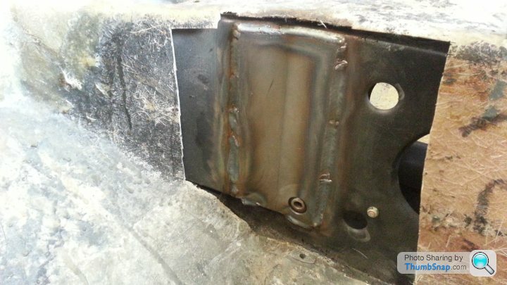
Tubes from cage to front of chassis. I would have preferred to have connected them the the damper uprights but this would have compromised the front wheel turning angle
Strengthening plates were welded to the chassis wherever the cage connected to it.
Quite a lot of tube under the dash.
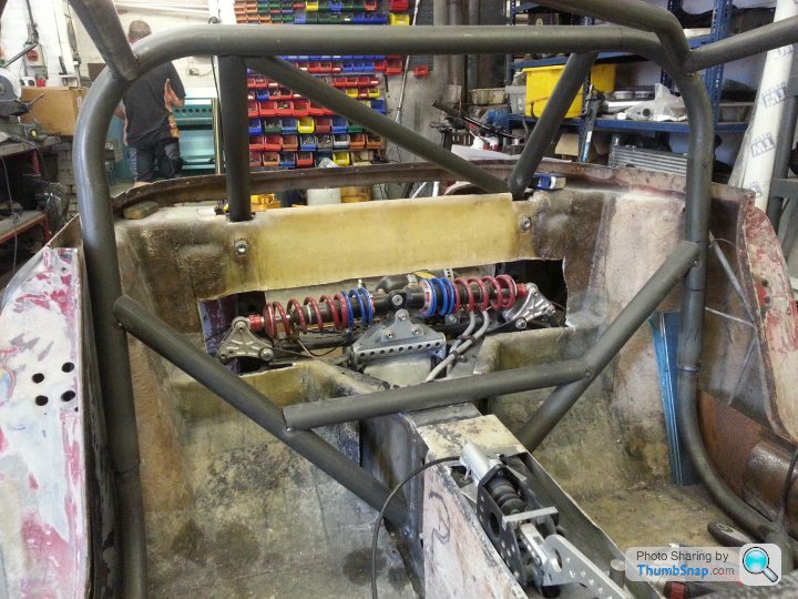
Finished cage (apart form a tube between the two suspension uprights) All of the fibreglass you see in the cabin area has now been replaced with carbon. The seat isn't being used (see earlier posts).
A full roll cage wasn't in my plans. Too bloody heavy. I planned to fit a hoop.
I got as far as a first fit before we decided to check how twisty the chassis actually was. It had been strengthened above and beyond the 26R racing Elan spec so I thought that it would be fine. However, it turned out to be like a stick licorice. Well,not that bad, it would have been more than adequate for 200-250bhp but no good for more than double that.
So a rethink was in order. I looked into stiffening using carbon fibre as an extra skin. This would have worked, possibly, but it would have been difficult with no guarantee of success. In the end I had to concede that the right way to go was full roll cage. I hated the thought of all that extra weight but consoled myself with the fact that without it I wasn't going to go fast. The added bonus was that I would be a lot safer.
Next step then was to get a cage, or so I thought. It quickly dawned on me that there was only one cage commercially available for the Elan, one made by Safety Devices. However, a quick look at this convinced me that it was not suitable for my purpose. It would save you in a crash but doesn't add much to the torsional stiffness of the chassis.
The only solution was to design my own. There followed quite few evenings downloading every photo I could find of Elans with roll cages. Although there was nothing that exactly meet my criteria they gave me ideas and a design slowly formed in my head. However, when I started to discuss my plans with my fabricator and Graham from Graham Hatherway Racing, a better design evolved.
Next step was to buy the steel. As I didn't much like the idea of filling the car with heavy steel I decided to use T45 seamless tube. Although it is the same weight size for size as normal cage steel it is much stronger so a thinner wall can be used and still have a stronger cage. The only down side is the cost. The tube cost me £750 but saved 13kg.
The car and tube was delivered to Martin at Graham's shop and the chassis leveled. We then spent a couple of days crawling over the car refining the design. The big problem is that you can't weld to fibreglass and I was out of sky hooks so we had to devise a cage (so it evolved again) that didn't need to be fixed to the floor, so it was effectively a space frame. It was nearly four days before we actually cut our first tube and the whole job took four weeks and more changes were made as the build progressed (for example, the initial plan didn't allow for tubes through the firewall into the engine bay, connecting to the chassis close to the front suspension uprights.
Because of the small cabin, we spent a lot of time getting the cage to fit as snugly as possible to the cabin sides. I think we did a pretty good job in this respect.
Ready for the off. Notice tube strapped down under the car.
Car being set up
Martin with the first section, always the most difficult piece as everything else is related to this bit.
First section in place
Rear section tacked together.
Tubes from cage to front of chassis. I would have preferred to have connected them the the damper uprights but this would have compromised the front wheel turning angle
Strengthening plates were welded to the chassis wherever the cage connected to it.
Quite a lot of tube under the dash.
Finished cage (apart form a tube between the two suspension uprights) All of the fibreglass you see in the cabin area has now been replaced with carbon. The seat isn't being used (see earlier posts).
Edited by stevebroad on Tuesday 3rd January 23:32
I needed some more carbon angle so decided to make a length out of carbon cloth offcuts. I could buy a 1200mm x 25mm by 25mm length from easycomposites for £58 plus shipping but by making it myself the cost is minimal. Admittedly, it won't be as good but it won't be visible so no problem :-)
The arty farty framing was caused by the phone cover around the lens coming loose :-)
https://youtu.be/fhtr6YY86nw
A minute or so after switching on vacuum
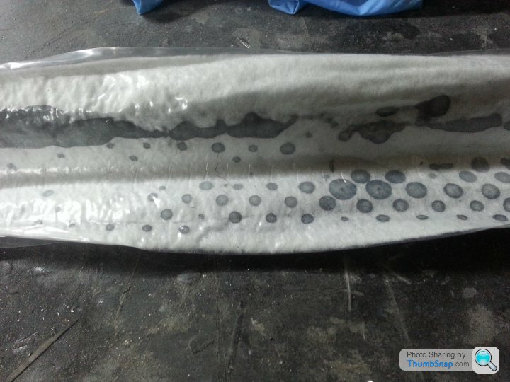
Ten minutes later
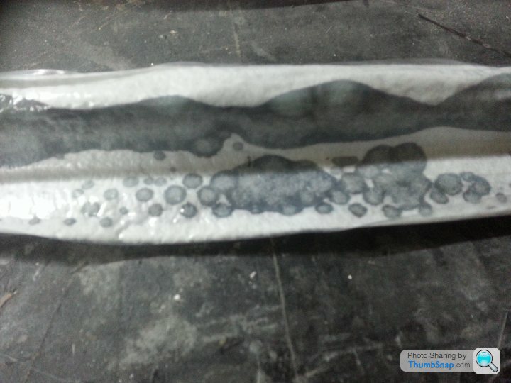
Now I just have to wait until tomorrow to see the result.
The arty farty framing was caused by the phone cover around the lens coming loose :-)
https://youtu.be/fhtr6YY86nw
A minute or so after switching on vacuum
Ten minutes later
Now I just have to wait until tomorrow to see the result.
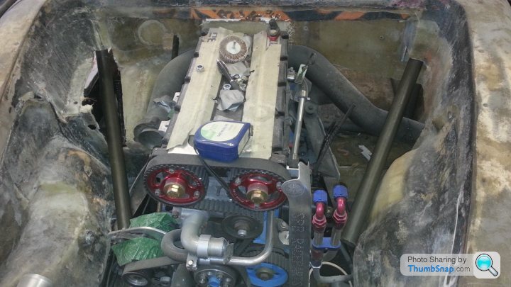
Wow OP,fantastic project. I wouldn't know where to start. Would you mind tell me the origins of the engine, what has been done(will be done) to it. Did I see two monster turbos on it? Has it been dynode . And what quarter mile are you expecting. I assume this will be a 9 sec car/150mph?
Gassing Station | Readers' Cars | Top of Page | What's New | My Stuff