Pembleton mkII - Tin Tub
Discussion


After going to see duncan, I realised that I'd need some more tools.
I've bought a crappy vice mounted english wheel (enough for 1.2ali but I don't think it'd deal with steel). A shrinker/stretcher, left/right tin snips and some straight tin shears. Various hammers/dollies etc.
I've had a quick go on some scraps taken from work. Its pretty cool what you can do with metal in a few mins!
Its very rough, but for 5 mins first attempt I'm quite pleased.
Progress has been slow to non-existant in recent weeks. We're stacked out at work, and I've been away for the last 2 weekends.
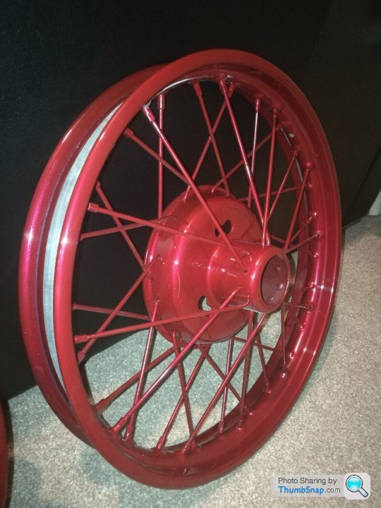
I have started to paint my wheels though. I've gone for a cherry red colour. I like the red wheels wheels that are going on victoria, but for the this one I wanted something a little less in your face. The colour is actually Citroen Wicked Red.
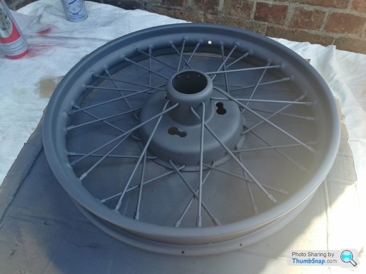
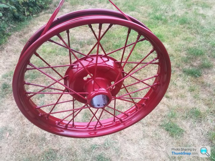
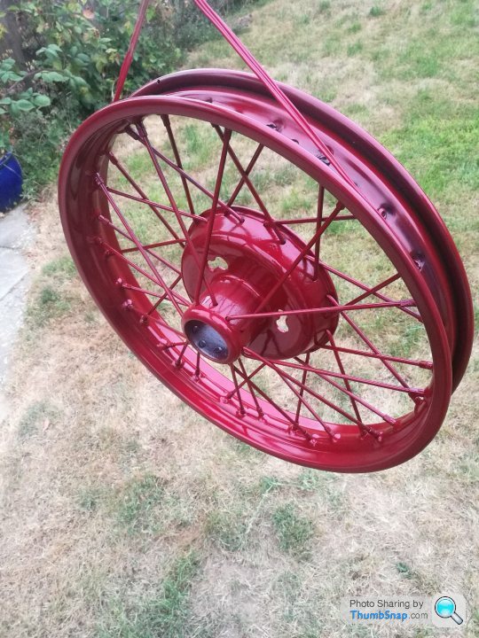
Cant wait to see what they look like all finished with the tyres on.
I have started to paint my wheels though. I've gone for a cherry red colour. I like the red wheels wheels that are going on victoria, but for the this one I wanted something a little less in your face. The colour is actually Citroen Wicked Red.
Cant wait to see what they look like all finished with the tyres on.
dxg said:
I thought this thread might be an appropriate place to ask for views on the Burton...
I've just stumbled across them and think they are stunning: http://www.burtoncar.com/?language=en&sort=2a .
Anyone have any experience?
As TooMany2cvs has said, they look like good quality kits and they're certainly pretty. I've just stumbled across them and think they are stunning: http://www.burtoncar.com/?language=en&sort=2a .
Anyone have any experience?
I've seen quite a few and never thought a single one looked cheap and nasty, which is rare for kit cars. I haven't looked over one in a lot of detail as they've never really been on my "list", I prefer a deficit in wheels.
If you are seriously considering building one, depending where you are in the country I could potentially put you in contact with an owner.
As ever, crusty cheap 2cv's are getting harder to find. One of the manufacturers (cant remember which one, possibly Lomax) used to get given free 2cvs as donors. They would break them down and put together complete donor packs on a pallet for £50 for people buying a kit at the same time, then sell the rest as spares or weigh in.
Unfortunately theres not a huge amount to update this time round.
Work got absolutely mental over the summer as the project I was working on was coming to an end. This finished in mid september, and I planned to take 4-6weeks off before looking for something else. This would give me some decent quality time in the garage. On my first week off I did all the little s tty jobs in the house, laying shed base, putting new taps in, replacing cooker hob, fixing draws etc... so I could spend some solid uninterrupted time in the garage.
On the thursday of the first week I got a call from a company I'd worked at previously, saying they're desperate for people and could I start on monday... not one to turn down interesting work and very local I agreed....
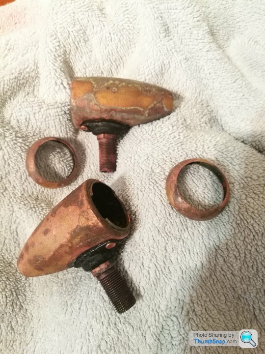
In the meantime I did manage to rig up an electrolysis tank to reverse chrome plating.
I love the look of polished brass, and most of the parts I've bought are older car parts that are chrome over brass where the chrome is pitted and damaged.
I set up a small plastic bucket and filled it with water. Added caustic soda (available from any hardware store, its used for cleaning drains) to it and stirred it in.
I used a scrap strip of 3mm mild steel for the anode and connected it to the negative of a car battery charger. Then hung the item to be stripped from a bit of wire and connected that to the positive, making sure they don't touch.
Use thick steel wire to hold the item in the container (a wire coat hanger is perfect) as the process just eats any thin or copper wire and drops the part in the bucket. I made this mistake and had to fish my parts out a few times
The steel plate fizzes, indicating its working....
After about 20minutes you get something that looks like this....
After rinsing with a scouring pad...
And cleaning up on the wire wheel...
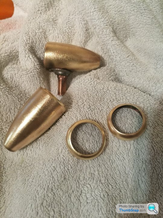
Ready for polishing... I have a few bits to do, so will post an image of them all together when done.
Work got absolutely mental over the summer as the project I was working on was coming to an end. This finished in mid september, and I planned to take 4-6weeks off before looking for something else. This would give me some decent quality time in the garage. On my first week off I did all the little s
tty jobs in the house, laying shed base, putting new taps in, replacing cooker hob, fixing draws etc... so I could spend some solid uninterrupted time in the garage.On the thursday of the first week I got a call from a company I'd worked at previously, saying they're desperate for people and could I start on monday... not one to turn down interesting work and very local I agreed....
In the meantime I did manage to rig up an electrolysis tank to reverse chrome plating.
I love the look of polished brass, and most of the parts I've bought are older car parts that are chrome over brass where the chrome is pitted and damaged.
I set up a small plastic bucket and filled it with water. Added caustic soda (available from any hardware store, its used for cleaning drains) to it and stirred it in.
I used a scrap strip of 3mm mild steel for the anode and connected it to the negative of a car battery charger. Then hung the item to be stripped from a bit of wire and connected that to the positive, making sure they don't touch.
Use thick steel wire to hold the item in the container (a wire coat hanger is perfect) as the process just eats any thin or copper wire and drops the part in the bucket. I made this mistake and had to fish my parts out a few times
The steel plate fizzes, indicating its working....
After about 20minutes you get something that looks like this....
After rinsing with a scouring pad...
And cleaning up on the wire wheel...
Ready for polishing... I have a few bits to do, so will post an image of them all together when done.
Edited by Ambleton on Sunday 14th October 09:23
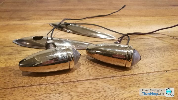
The side lights will be used as Indicators with orange bulbs. Here they are polished up...
I managed to get another pair from an auto jumble, so I'll have matching front/rear now, which is nice...
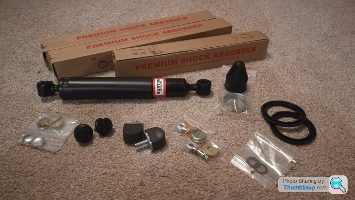
I also had another delivery of parts from ECAS today... mostly chassis fittings and nice new top quality dampers, but also some king pin fittings, brake adjusters, seals etc.
Doesn't look like much for £250+...
I managed to get another pair from an auto jumble, so I'll have matching front/rear now, which is nice...
I also had another delivery of parts from ECAS today... mostly chassis fittings and nice new top quality dampers, but also some king pin fittings, brake adjusters, seals etc.
Doesn't look like much for £250+...
I feel ashamed for the lack of updates and slow progress on this thread, but a few things have been ticking along in the background.
I trial fitted my rear suspension arm, wheel adaptor and wire wheel on my bare chassis and very carefully placed a centre line on the vehicle with some string. I wanted it to be bang on, so this process probably took me about 45mins measuring and eying up.
I then dropped a plumb line down to the rim and measured up, articulating the arm as I measured. This resulted in a requirement for 14mm to be removed from the width if the suspension arm.
I took it down to a local motorsport fabrication shop with a spare cross beam and a wheel but and they made up a jig and did the job, re-instating a thicker inner wall slug that was lurking beneath the outer skins. This has now been painted and awaiting brake and hub reassembly.
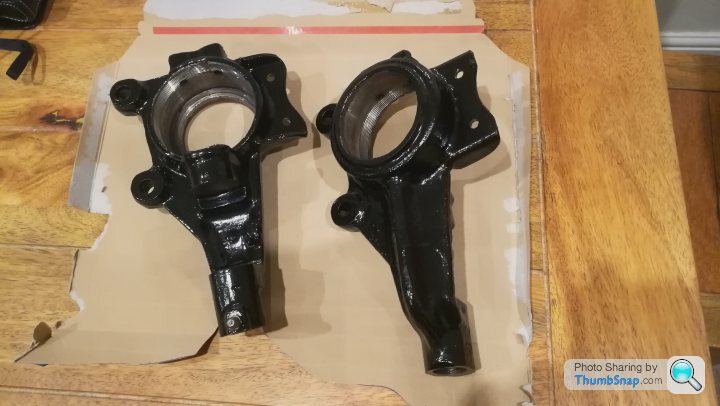
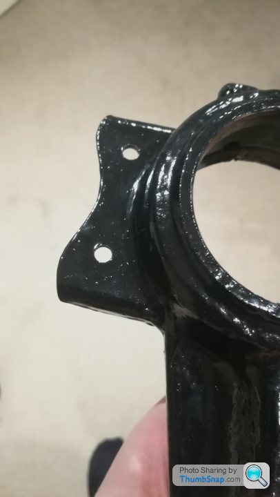
Whilst they were doing some structural welding, I asked them to knock up and tag on some more wing mounts to the front uprights in some 10guage, planar with the existing mounts. I provided a simple jig and cardboard template as well as some old lock-rings to ensure it didn't pull the housing out of shape.
These are now painted and ready to be assembled onto the arms....
I've also made my big order for all me sheet metal that I'll need to make the bodywork. That'll be arriving next week.
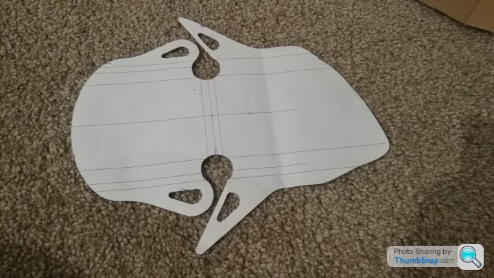
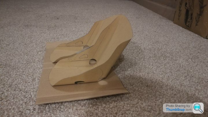
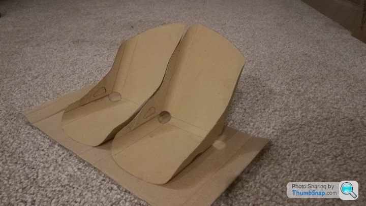
In other news ive also mocked up a very basic seat pattern to make my own aluminium bomber type bucket seats. They will have padding on the lower back and seat pad. I need to make a few modifications to the design before I scale up to full size in card, then into aluminium.
I trial fitted my rear suspension arm, wheel adaptor and wire wheel on my bare chassis and very carefully placed a centre line on the vehicle with some string. I wanted it to be bang on, so this process probably took me about 45mins measuring and eying up.
I then dropped a plumb line down to the rim and measured up, articulating the arm as I measured. This resulted in a requirement for 14mm to be removed from the width if the suspension arm.
I took it down to a local motorsport fabrication shop with a spare cross beam and a wheel but and they made up a jig and did the job, re-instating a thicker inner wall slug that was lurking beneath the outer skins. This has now been painted and awaiting brake and hub reassembly.
Whilst they were doing some structural welding, I asked them to knock up and tag on some more wing mounts to the front uprights in some 10guage, planar with the existing mounts. I provided a simple jig and cardboard template as well as some old lock-rings to ensure it didn't pull the housing out of shape.
These are now painted and ready to be assembled onto the arms....
I've also made my big order for all me sheet metal that I'll need to make the bodywork. That'll be arriving next week.
In other news ive also mocked up a very basic seat pattern to make my own aluminium bomber type bucket seats. They will have padding on the lower back and seat pad. I need to make a few modifications to the design before I scale up to full size in card, then into aluminium.
Tonight I started to reassemble my rear drum brake. The piston is working fine and I've been told by many people not to fiddle with stuff unless it's broke...
Ive been forced to ignore my mantra of "if it aint broke, fix it 'till it is". It has been installed with new fitting kit, and new shoes. The adjusters were absolutely shagged and these were cut off. Fortunately ECAS sell some new adjusters made by Burton2cv in the Netherlands that are a doddle to fit!

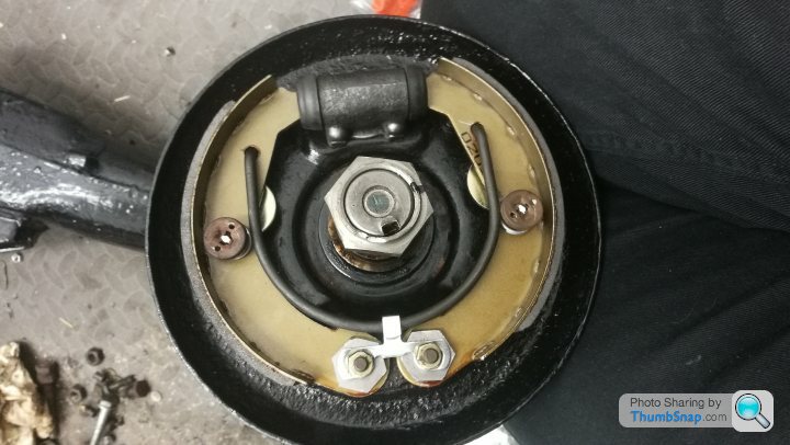
I have a spare drum that I need to cut up in order to use as an alignment tool for the eccentrics. Once this is done, the drum will be fitted with a new bearing and hub nut.
Ive been forced to ignore my mantra of "if it aint broke, fix it 'till it is". It has been installed with new fitting kit, and new shoes. The adjusters were absolutely shagged and these were cut off. Fortunately ECAS sell some new adjusters made by Burton2cv in the Netherlands that are a doddle to fit!
I have a spare drum that I need to cut up in order to use as an alignment tool for the eccentrics. Once this is done, the drum will be fitted with a new bearing and hub nut.

Thanks Nunga, although there really isn't that much to it...
My rear arm is now fitted and I have routed the rear brake line in some clips, protected by some rubber tubing I had lying around. It then disappears into the main axle tube on a clocking spring. I have made an oversized hole in the tube so the brakeline feeds out onto one of the chassis rails to allow for easy routing to the front.
Next is to finish installing my rivnuts for the fuel tank mounting from below. This will allow removal of the fuel tank in the future if required and for ease of mounting. This would be almost impossible otherwise and neater than a weld nut...
Will post some images over the weekend if I remember.
That little rumble/dickie seat looks great! Although maybe not the safest mode of transport for little ones!
As ever, life appears to be getting in the way of the build, although I have done a few bits recently.
The springs I've gone for are uprated. The length and ID have to be the same as original, but because if the thicker wire, the OD has increased over the standard 2cv springs. This means that the springs and cups would rub and squeak on the underside of the floor and make them also not run true.
In order to overcome this, I will be cutting holes in the floor panel where the springs sit, and I have made 3 identical blisters which will be bonded and riveted in place to clear the springs. They were a bit if a faff to make, naturally, the third was much easier than the first one!
Edited by Ambleton on Thursday 28th February 23:22
I made an mdf former in two parts. A male and a female. I annealed the aluminium first, then clamped it in the two halves of the female former. Then placed the male on top and beat the st out of it with a lump hammer.
It took a lot of heavy blows to get it right. The next two times I did most of the work with a rubber ended mallet, then used the male plug to get the final shape. This seemed much quicker as instead of trying to stretch a lot of aluminium, the force was more focused.
I then tidied them all up on my wheel.
t out of it with a lump hammer.It took a lot of heavy blows to get it right. The next two times I did most of the work with a rubber ended mallet, then used the male plug to get the final shape. This seemed much quicker as instead of trying to stretch a lot of aluminium, the force was more focused.
I then tidied them all up on my wheel.
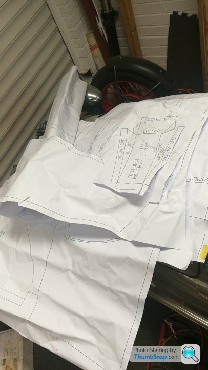
The "standard" patterns and way most people build thier pembletons has a rear bulkhead panel at the rear of the boot, before the rear wheel. This goes vertically up. Whilst this is simple to do and uses the least raw material, it means there's a lot of wasted space that could be otherwise utilised for boot storage/toolbox etc.
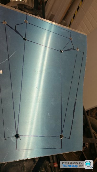
With this in mind I used CAD (CARBOARD AIDED DESIGN) to make a pattern to create an elongated rear deck and larger boot area...
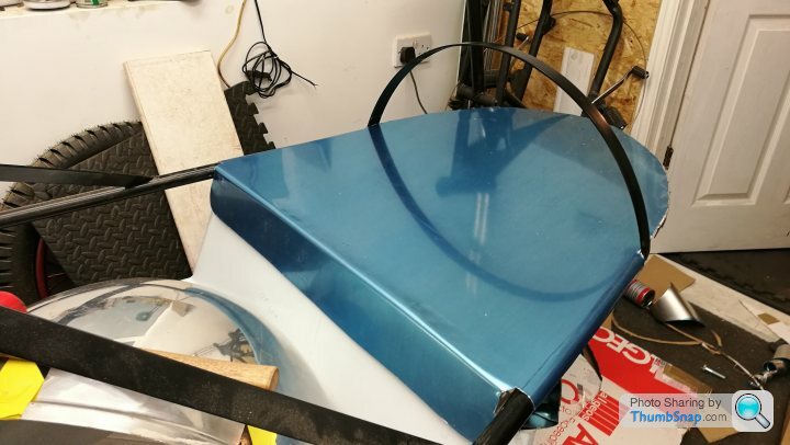
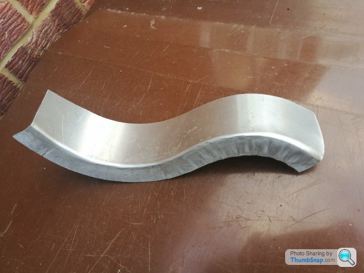
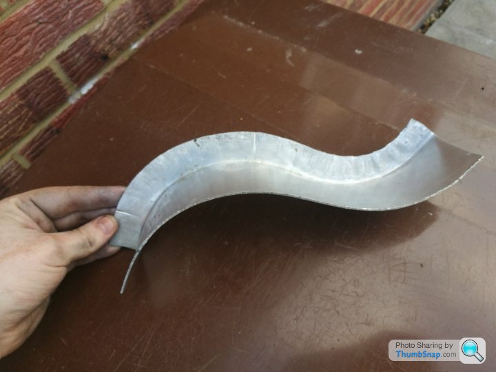
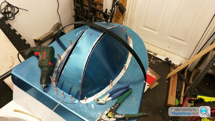
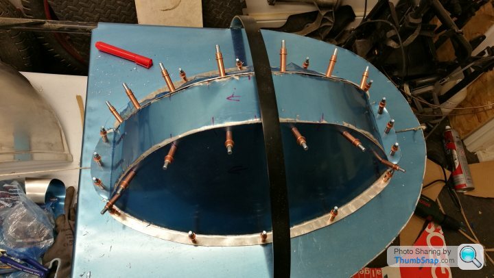
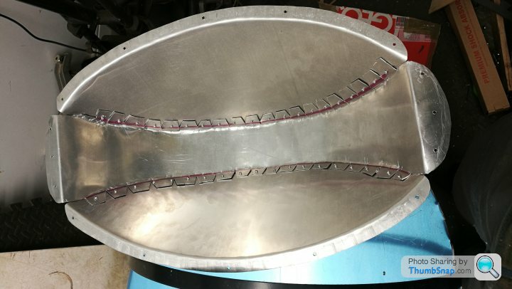
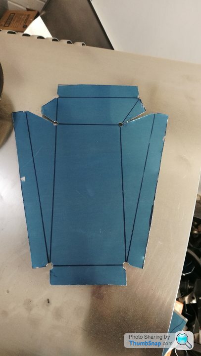
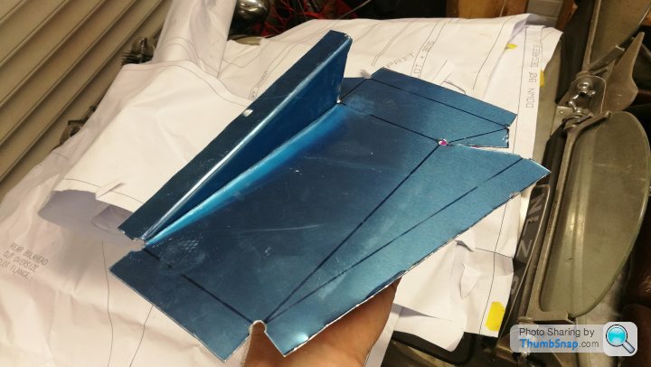
I then set about making a housing for the wheel/tyre. I could've made the sides of the housing vertical, but to allow enough room to remove the wheel from the splines, it made it really wide, and imo it looks a bit agricultural.
I used CAD again to create a pattern before making in aluminium... I made an error with the pattern first time round as I hadn't allowed enough curvature for the stretching of the flange...
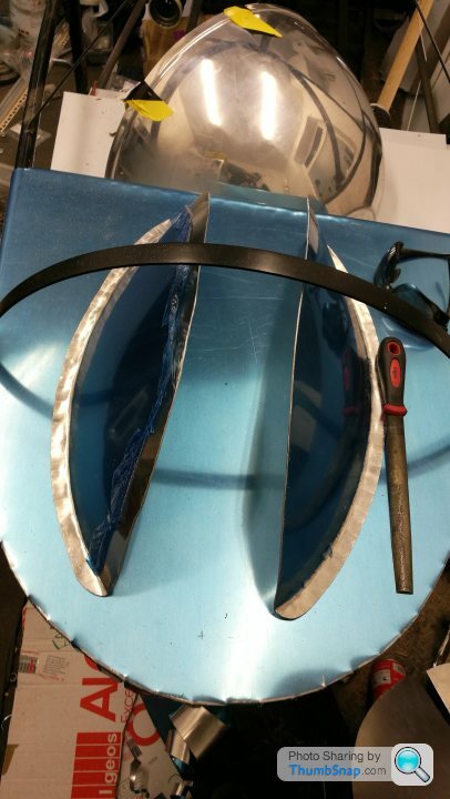
They were tricky little things to make, but very satisfying to get right. I've started to make the top closing panel, but no photos of that yet as its still WIP.
With this in mind I used CAD (CARBOARD AIDED DESIGN) to make a pattern to create an elongated rear deck and larger boot area...
I then set about making a housing for the wheel/tyre. I could've made the sides of the housing vertical, but to allow enough room to remove the wheel from the splines, it made it really wide, and imo it looks a bit agricultural.
I used CAD again to create a pattern before making in aluminium... I made an error with the pattern first time round as I hadn't allowed enough curvature for the stretching of the flange...
They were tricky little things to make, but very satisfying to get right. I've started to make the top closing panel, but no photos of that yet as its still WIP.
Here's a list of access panels that I intend to make to ensure any work required in future is reasonable straight forward.
1- removable panel where the steering column goes through the bulkhead. This is to allow the easy removal of the steering rack. On Victoria I had to use the tin snips on the bulkhead to get the rack out!
2- Panel on the upper horizontal face above the pedalbox. This is to allow easy modification or cable changes. Without it, you have to remove the seats and lie on your back in the footwell, legs in the air, messing around in the dark... its uncomfortable and very sweary.
3- Panel in the boot floor to allow access to the fuel sender and pick up.
4- removable panel inthe rear bodywork to get to the rear swing arm. Without this, the rear suspension arm would not be removable without some fairly heavy surgery.
I'm undecided wether I should make a boot opening hatch at present or just use the area through the back of the seats.
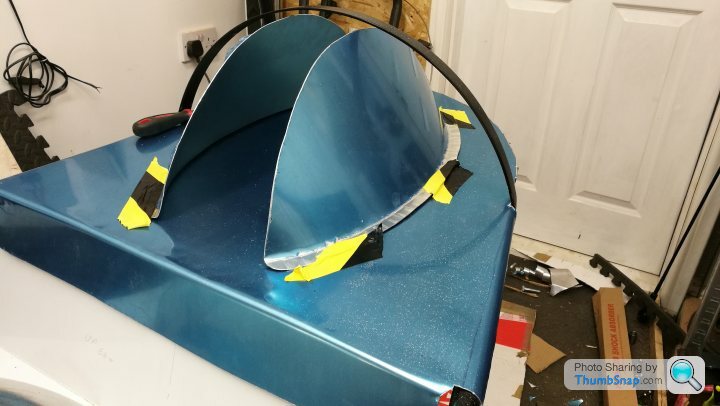
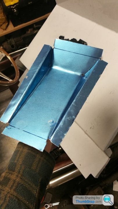
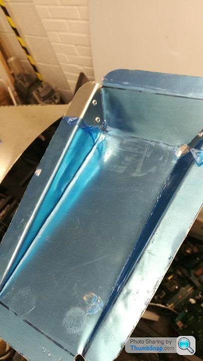
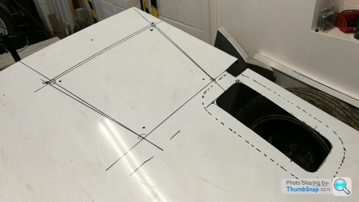
I finished off the rear wheel housing today (or the armadillo as the wife calls it).
Cleco pins are an absolute godsend!
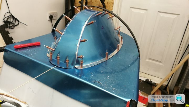
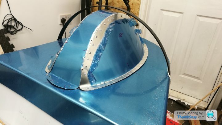
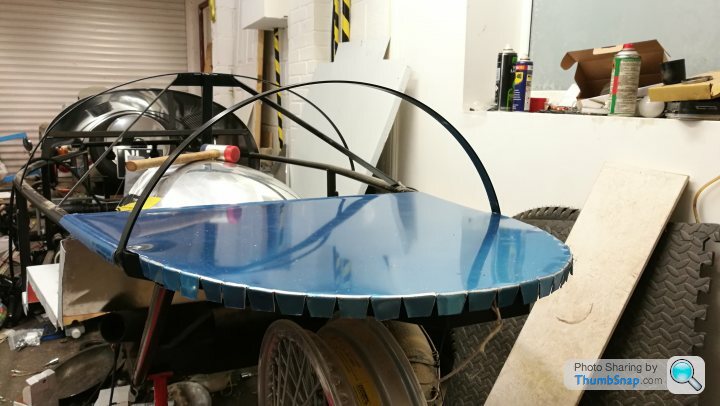
With the housing now made it was time to position it, then cut the hole in the floor... (please excuse the absolute state of the garage, its embarrassing really)...
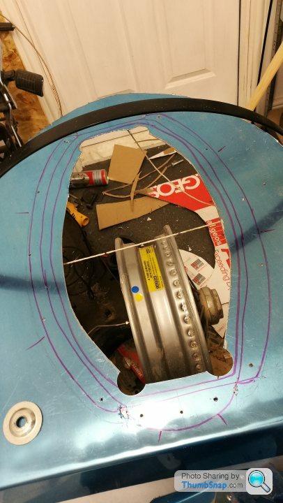
I ran around it and created a little lip all the way round

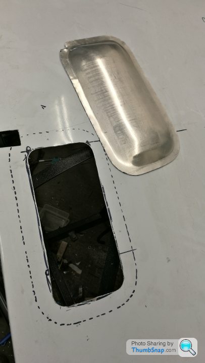
Next up I started to make a hatch to go in the boot floor, this will allow me to access the fuel sender and pick up later...
That's all for today folks, hopefully another update tomorrow if I'm allowed in the garage again.
Cleco pins are an absolute godsend!
With the housing now made it was time to position it, then cut the hole in the floor... (please excuse the absolute state of the garage, its embarrassing really)...
I ran around it and created a little lip all the way round
Next up I started to make a hatch to go in the boot floor, this will allow me to access the fuel sender and pick up later...
That's all for today folks, hopefully another update tomorrow if I'm allowed in the garage again.
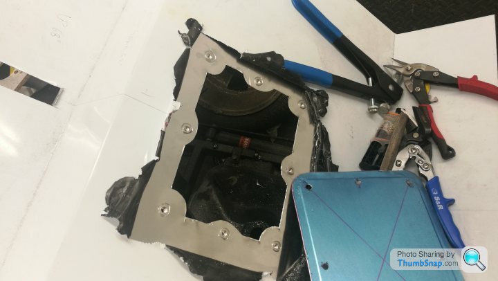
I cut the access hole for the fuel tank today and dressed the edges. I also inserted some rivnuts for the fixings.
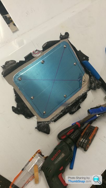
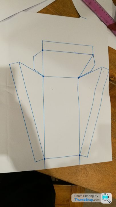
One job I was dreading was the footwell/heel recess for the floor. I'd heard that these were a bugger to make. I thought id document the whole process for interest....
Paper patterns!
Cut out ready to be transferred to the aluminium...
Transferred! Id had a tip from a few fabricators that you get a neater fold and n easier job if you drill a 6mm hole where corners come together...
The rest cut out using tin snips...
I then did a few folds. I dont have a break, so everything is done with by clamping in timber and knocking over the edge with a nylon hammer...
Once I was happy with the overall shape I knocked over the tabs and secured with rivets.

Now ive just got to make another thats a mirror image!
One job I was dreading was the footwell/heel recess for the floor. I'd heard that these were a bugger to make. I thought id document the whole process for interest....
Paper patterns!
Cut out ready to be transferred to the aluminium...
Transferred! Id had a tip from a few fabricators that you get a neater fold and n easier job if you drill a 6mm hole where corners come together...
The rest cut out using tin snips...
I then did a few folds. I dont have a break, so everything is done with by clamping in timber and knocking over the edge with a nylon hammer...
Once I was happy with the overall shape I knocked over the tabs and secured with rivets.
Now ive just got to make another thats a mirror image!
Not a huge amount more progress was made this afternoon... I planned and routed my brake pipe and electricals front-back.
Next I'll be routing fuel line, but first I need to order a new fuel sender/pick up unit...
Once all the services are fitted I can crack on and install the floor and bulkeads!
Next I'll be routing fuel line, but first I need to order a new fuel sender/pick up unit...
Once all the services are fitted I can crack on and install the floor and bulkeads!
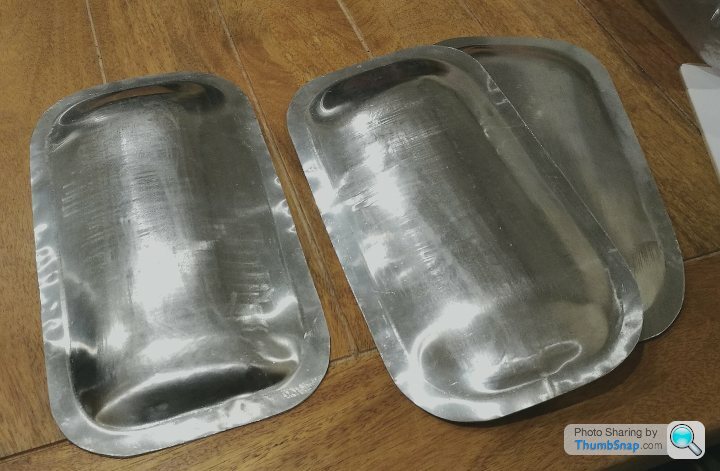
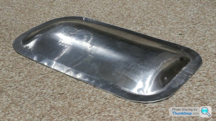
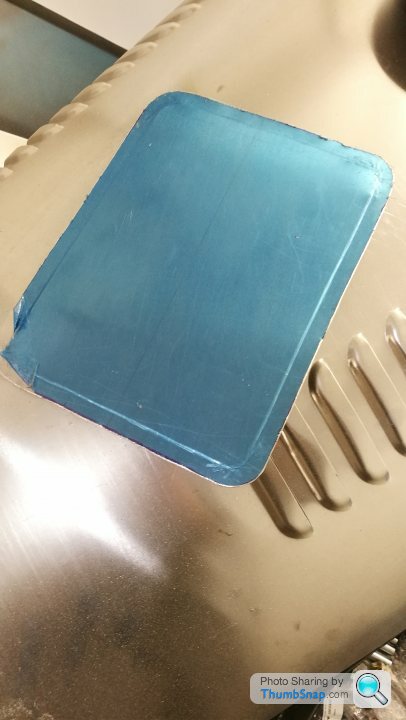
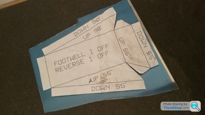
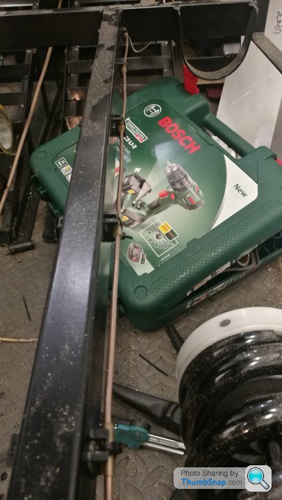
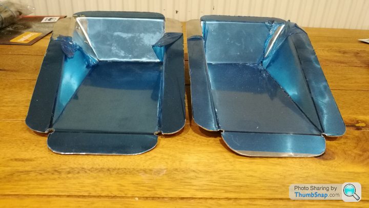
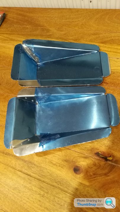
After making one foot well / heel recess yesterday I decided that for my size 11s it could do with being deeper. The accelerator/brake recess on Victoria is deeper than standard, but the clutch recess isn't, and it definitely feels nicer on the right...
So I remade the pattern, a tiny bit wider, and 20mm deeper and made a matching pair... it was so much easier this time round as I'd figured out the best fold order and changed my method slightly...
Here you can see the standard ine and the deeper one side-side
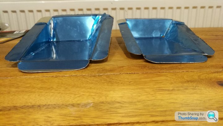
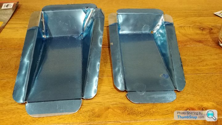
And the matching pair of deeper recesses....
So I remade the pattern, a tiny bit wider, and 20mm deeper and made a matching pair... it was so much easier this time round as I'd figured out the best fold order and changed my method slightly...
Here you can see the standard ine and the deeper one side-side
And the matching pair of deeper recesses....
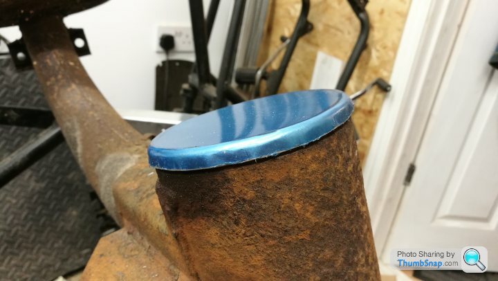
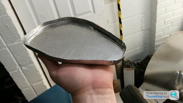
With the modified, turned around, rear arm the end cap/seal now doesn't fit. This stops most debris and other road crap getting into the end where the bearings are. This isn't the last seal, but it is the primary one (theres another seal on the castellated nut).
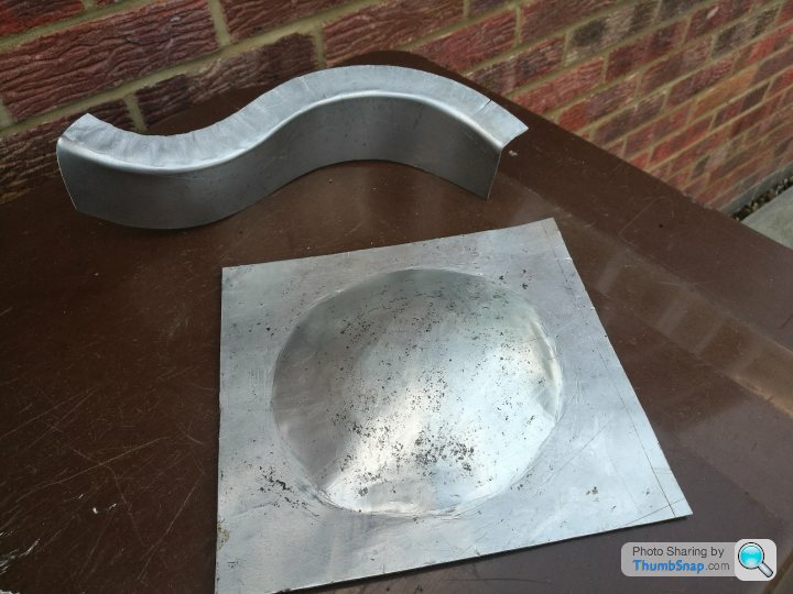
In order to make a new one I cut a disc of aluminium slightly bigger than the OD of the arm and knocked it over, working round with a nylon hammer... I used my spare RH suspension arm that is surplus to requirements. I was dubious as to wether this would work as I presumed I'd get puckered edges, but if you work your way around and make about 5 passes then it works beautifully! It holds on itself, but I'll give it a helping hand with a decent bead of TigerSeal or other PU sealant.

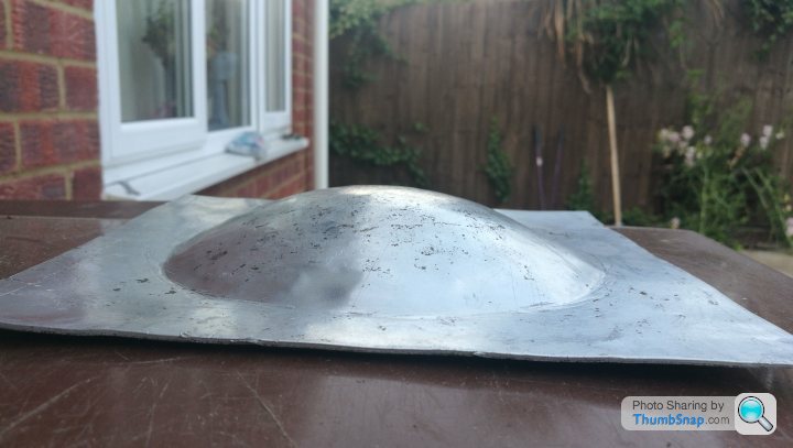
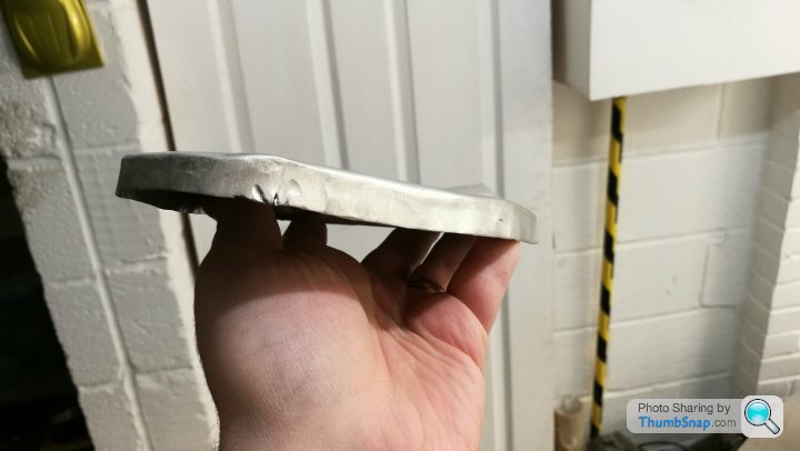
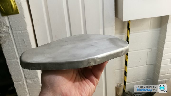
After this worked so well I made another larger one, with a deeper return, just to see the limits of what could be done. This also worked quite well.
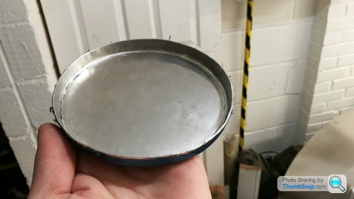
I then gave a more complex shape a try, a damper bracket/end cap for the front arms. This was less successful and I got some obvious puckering, but I think if I annealed the aluminium first and changed the knocking block and method, then I may get passable results.
In order to make a new one I cut a disc of aluminium slightly bigger than the OD of the arm and knocked it over, working round with a nylon hammer... I used my spare RH suspension arm that is surplus to requirements. I was dubious as to wether this would work as I presumed I'd get puckered edges, but if you work your way around and make about 5 passes then it works beautifully! It holds on itself, but I'll give it a helping hand with a decent bead of TigerSeal or other PU sealant.
After this worked so well I made another larger one, with a deeper return, just to see the limits of what could be done. This also worked quite well.
I then gave a more complex shape a try, a damper bracket/end cap for the front arms. This was less successful and I got some obvious puckering, but I think if I annealed the aluminium first and changed the knocking block and method, then I may get passable results.
I trial fitted the floor tonight and marked up there the spring blisters needed to go and cut them out.
I also marked up the floor for the heel recess too. Due to where the chassis rails are, the position of these is basically fixed.
Once this has been cut out then I can bond and rivet the floor down for real!
I also marked up the floor for the heel recess too. Due to where the chassis rails are, the position of these is basically fixed.
Once this has been cut out then I can bond and rivet the floor down for real!
Edited by Ambleton on Thursday 7th March 22:56
Gassing Station | Readers' Cars | Top of Page | What's New | My Stuff