325TI - Project Mpact
Discussion


Future Proofing Part 2,
Yet more Reinforcement, the plan here is to join each layer of the boot floor together. This will allow the the Subframe bolts to pass through to the inside of the car Sandwiching each layer of the floor.
There seems to be a few different ways of achieving this, kits that can be bought and bonded/riveted in, some home made attempts, and various braces that can be fitted from the rear shock top mounts down to the Subframe bolts.
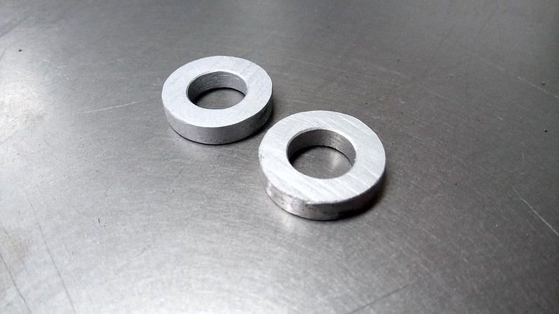
To start with i extended a drill bit long enough to reach through each layer of the boot floor from underneath, an aluminium spacer was turned on a lathe to fit inside the mounting holes where the subframe bolts locate, this protects the internal thread from any damage and the the extended drill bit goes up through the hole on the inside of the aluminium, this keeps the drill bit centered.

After drilling from the underside, I then went into the boot. Where the drill bit had past through the boot floor I then opened it up with a hole cutter on both sides.
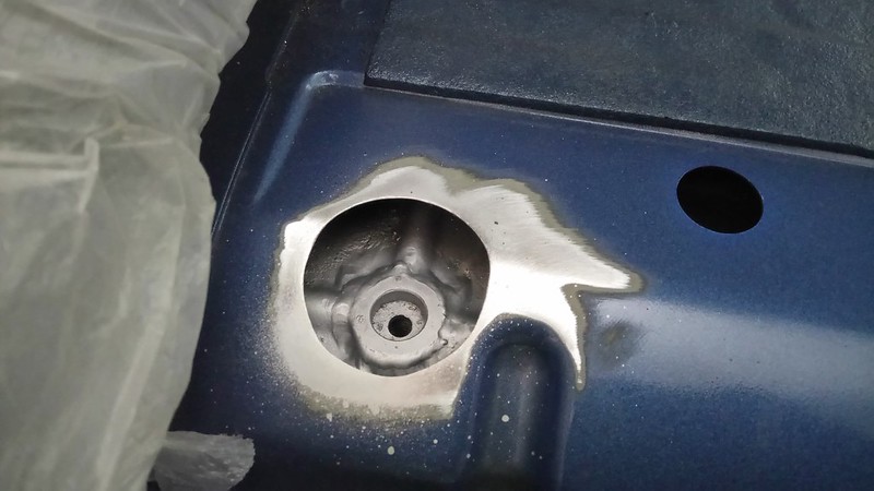
This revealed a cavity where the top of the Subframe threaded mount joins one layer of the floor, you can just about see the factory MIG welds.

There is a raised bead section, that is there for structural reasons and shouldn't be flattened. Instead i used a small hole cutter, cut away the center of the raised bead, this then revealed the top of the threaded section where the Subframe bolts locate.
Then, I turned two small spacers (one for each side) with an outside diameter the same size as the hole cutter that was used, and an inside diameter to clear an M12 bolt and sprayed with weld through primer.
The spacers were then placed in the hole and fully TIG welded, the TIG welds picked up onto the factory MIG welds. This closed the gap where the beaded section was and gave a good mounting point for the next stage.
Two little tubes were then rolled and capped one end, the smaller holes are for puddle welds.

After spraying with weld through primer, both tubes were fully TIG welded into the car. The small puddle welds located onto the spacer in the previous stage.
All welds were then cleaned up with a power file.

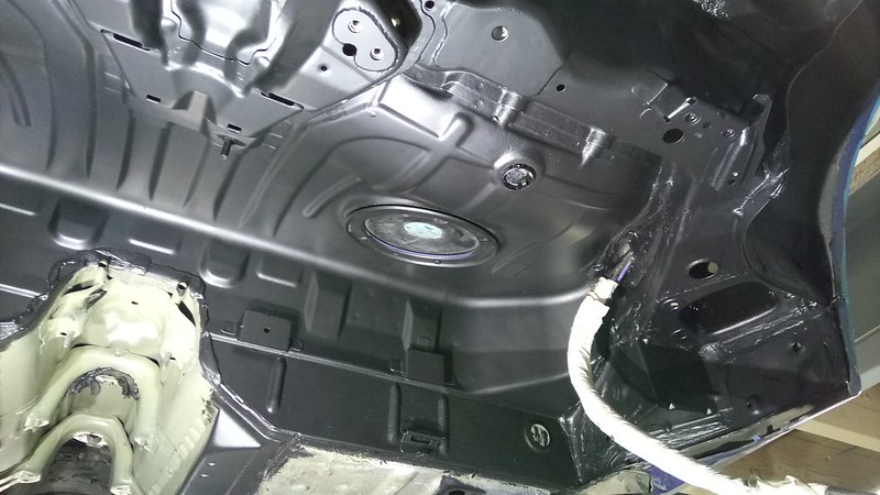
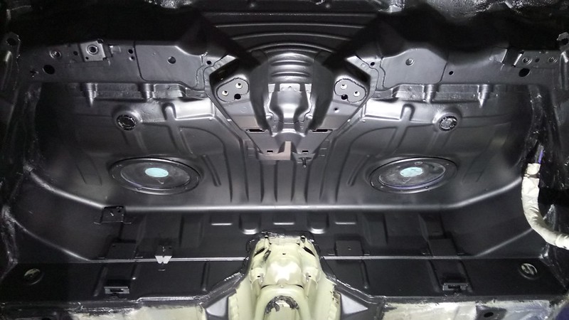
This now allows the rear Subframe bolts to pass through into the car, sandwiching each layer and closes any cavities.
Yet more Reinforcement, the plan here is to join each layer of the boot floor together. This will allow the the Subframe bolts to pass through to the inside of the car Sandwiching each layer of the floor.
There seems to be a few different ways of achieving this, kits that can be bought and bonded/riveted in, some home made attempts, and various braces that can be fitted from the rear shock top mounts down to the Subframe bolts.
To start with i extended a drill bit long enough to reach through each layer of the boot floor from underneath, an aluminium spacer was turned on a lathe to fit inside the mounting holes where the subframe bolts locate, this protects the internal thread from any damage and the the extended drill bit goes up through the hole on the inside of the aluminium, this keeps the drill bit centered.
After drilling from the underside, I then went into the boot. Where the drill bit had past through the boot floor I then opened it up with a hole cutter on both sides.
This revealed a cavity where the top of the Subframe threaded mount joins one layer of the floor, you can just about see the factory MIG welds.
There is a raised bead section, that is there for structural reasons and shouldn't be flattened. Instead i used a small hole cutter, cut away the center of the raised bead, this then revealed the top of the threaded section where the Subframe bolts locate.
Then, I turned two small spacers (one for each side) with an outside diameter the same size as the hole cutter that was used, and an inside diameter to clear an M12 bolt and sprayed with weld through primer.
The spacers were then placed in the hole and fully TIG welded, the TIG welds picked up onto the factory MIG welds. This closed the gap where the beaded section was and gave a good mounting point for the next stage.
Two little tubes were then rolled and capped one end, the smaller holes are for puddle welds.
After spraying with weld through primer, both tubes were fully TIG welded into the car. The small puddle welds located onto the spacer in the previous stage.
All welds were then cleaned up with a power file.
This now allows the rear Subframe bolts to pass through into the car, sandwiching each layer and closes any cavities.
Edited by amc_adam on Friday 20th December 16:54
amc_adam said:
It's certainly been long awaited!. Yes i still have the caddy, it's in the garage collecting dust waiting for an engine in that too 
So that's Compact, Caddy, Mini and Dan's M3 that I'm sure you'll be roped into making bits for.... how do you still find time to get to the gym!eezeh said:
Are you planning on joining the strut mounts with the subframe mounts with bracing or does this negate the need for that?
First dibs on the car when you come to sell it!
I may do a at a later date, i don't want anything that takes up the boot space. For the time being I'm going to have a brace going to the chassis legs, it will be hidden under the carpet so no one is going to be able to see it.First dibs on the car when you come to sell it!
Ha, i don't think it will be going up for sale!
With the rear Subframe mounts done, it was on to the front Subframe mounts........ this turned out to be a bigger job that expected.
A ''Why did i start this'' moment.
When i was doing a bit of research before getting stuck in, i thought it would be just as simple as doing the rear Subframe mounts.
Nope, that would be too easy!
While drilling from the underside using the same method as the last time (extended Drill bit and aluminium spacer) it seemed to take a bit longer, and a few more layers of floor?!.
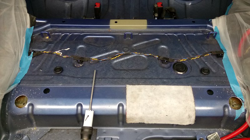
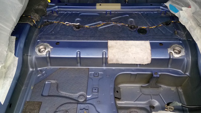
The research i had done previously was on coupes, I'd never seen anything done on a compact. I have found that compacts have an extra layer/brace running across from one chassis leg to another, probably due to the hatch back design it needed it to stop the body flexing.
Picture shows the standard brace in the compacts, just behind the rear seats.

For the car this is a good thing as i won't need to make a brace from one chassis leg to the other, for me that extra layer was a problem.
As i started drilling from the inside the car using a hole cutter i had to then try and go through two layers, but the hole cutter depth isn't capable of doing this.

I really did not want to do the next step, but there was no going back! I had to carefully drill each factory spot weld and then choose where to use an angle grinder with a cutting disc and cut up a perfectly good panel. For me this seemed a bit excessive, but it was at the point where there was no going back
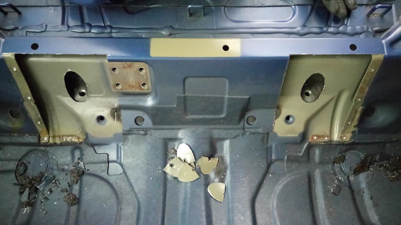
The panel that has the factory 'E-coat' Green colour is what the coupes have, the bit I've had to remove is the extra brace panel compacts have.
You can see the top of the threaded Subframe mounts in the above picture, this is where i will clean the paint off and then weld through prime.
Two more tubes rolled and welded, the capped ends have small holes for puddle welding to the factory MIG welds where Subframe bolts locate.

Everything was then sprayed in weld through primer,

The tubes were held in place using two wheel bolts and then one layer was fully TIG welded in place. Again, sprayed in weld through primer.


And then the top layer back on in its original place,


That was a job i didn't like doing!
A ''Why did i start this'' moment.
When i was doing a bit of research before getting stuck in, i thought it would be just as simple as doing the rear Subframe mounts.
Nope, that would be too easy!
While drilling from the underside using the same method as the last time (extended Drill bit and aluminium spacer) it seemed to take a bit longer, and a few more layers of floor?!.
The research i had done previously was on coupes, I'd never seen anything done on a compact. I have found that compacts have an extra layer/brace running across from one chassis leg to another, probably due to the hatch back design it needed it to stop the body flexing.
Picture shows the standard brace in the compacts, just behind the rear seats.
For the car this is a good thing as i won't need to make a brace from one chassis leg to the other, for me that extra layer was a problem.
As i started drilling from the inside the car using a hole cutter i had to then try and go through two layers, but the hole cutter depth isn't capable of doing this.
I really did not want to do the next step, but there was no going back! I had to carefully drill each factory spot weld and then choose where to use an angle grinder with a cutting disc and cut up a perfectly good panel. For me this seemed a bit excessive, but it was at the point where there was no going back
The panel that has the factory 'E-coat' Green colour is what the coupes have, the bit I've had to remove is the extra brace panel compacts have.
You can see the top of the threaded Subframe mounts in the above picture, this is where i will clean the paint off and then weld through prime.
Two more tubes rolled and welded, the capped ends have small holes for puddle welding to the factory MIG welds where Subframe bolts locate.
Everything was then sprayed in weld through primer,
The tubes were held in place using two wheel bolts and then one layer was fully TIG welded in place. Again, sprayed in weld through primer.
And then the top layer back on in its original place,
That was a job i didn't like doing!
Edited by amc_adam on Friday 20th December 18:23
agent006 said:
Would be a terrible shame if your company name was to slip accidentally into one of your posts. Obviously completely against forum rules, just like putting your website on your profile.

I was going to keep the two apart as i'm building the Compact for myself rather than advertisement for my business, but if you are interested in other projects I've done you can see them by looking for 'Artisan MetalCraft' on social media 
Future Proofing part 3
Chassis leg plates, there will be a brace going from one chassis leg to the other picking up on the mounting bolts of the subframe.
I didn't just want to drill and nut insert the Chassis legs, Rather fabricate two plates following the contours of the leg with two threaded fixings TIG welded to the plates. Then, drill two holes into the Chassis legs to clear the threaded fixings and fully TIG weld the plates to the chassis legs.
Two plates in 2mm steel (handed left/right) shaped to the contours of the Chassis legs. The smaller holes are for puddle welds, then sprayed in weld through primer.

Fully TIG welded in


Chassis leg plates, there will be a brace going from one chassis leg to the other picking up on the mounting bolts of the subframe.
I didn't just want to drill and nut insert the Chassis legs, Rather fabricate two plates following the contours of the leg with two threaded fixings TIG welded to the plates. Then, drill two holes into the Chassis legs to clear the threaded fixings and fully TIG weld the plates to the chassis legs.
Two plates in 2mm steel (handed left/right) shaped to the contours of the Chassis legs. The smaller holes are for puddle welds, then sprayed in weld through primer.
Fully TIG welded in
Edited by amc_adam on Friday 20th December 18:45
Gassing Station | Readers' Cars | Top of Page | What's New | My Stuff