540HP NA 7L V12 3 seater
Discussion


samoht said:
A couple of cars you might consider examining closely for inspiration / parts:
- the Cizeta Moroder V16 is the only other car I know of like this, two Lambo V8 engines mounted transversely driving a transaxle, very similar layout to what you're thinking. So it proves it can work, and the way they did it might be worth looking at.
- I think the Porsche 917 has a central power takeoff, being formed from two flat sixes
- McLaren closely based the F1 greenhouse on the Toyota Sera, which also has doors that open that way. So you could just possibly use parts of that car for your greenhouse? Could be a shortcut to a set of glass and doors, seals etc that fit together properly without leaks.
Thanks for the excellent images, I had not seen such a good shot of the bare cizeta block before. The V16T was an early inspiration, however I do not want to attempt full integration of the cranks and blocks. Keeping the engines as separate "plug and play" units frees me up in the future, so the Tbox unit can be adapted to suit any pair of engines.- the Cizeta Moroder V16 is the only other car I know of like this, two Lambo V8 engines mounted transversely driving a transaxle, very similar layout to what you're thinking. So it proves it can work, and the way they did it might be worth looking at.
- I think the Porsche 917 has a central power takeoff, being formed from two flat sixes
- McLaren closely based the F1 greenhouse on the Toyota Sera, which also has doors that open that way. So you could just possibly use parts of that car for your greenhouse? Could be a shortcut to a set of glass and doors, seals etc that fit together properly without leaks.
I originally intended to build a replica Mazda 787B racecar with 2 x 20B Triple rotor engines - then you are talking insane power and super low COG - would probably go better than an original one! But decided to go this road car route as I will get more use out of it and it hopefully won't be so lethal.
Thanks for the Sera idea, unfortunately I don't think there are any in NZ.
Weighed the wet but mostly bare honda J35Z2 engine - 122kg. I am OK with that mass given were it sits in the car.
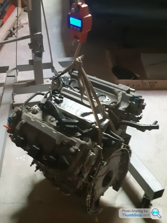
Have bought an old Xbox kinect unit that can be converted into a 3D scanner so I will be able to accurately scan the engine shown above.
Pulled a J32A1 head from a 225hp 1999 honda saber at the wreckers - intending to use it as a sacrificial lamb to explore head porting, cam and flowbench improvements as it wasn't the high power J32A2. Not sure how well the ports will scan - not a high priority. Will post some pics of the cabin mock up shortly.

small progress update - I am currently building the inner rear bulkhead mould plug which incorporates the inner tub spars and the passenger seats. My carpentry skills are improving slowly - hence no photos yet. The mockup of the entry and exit technique has proven useful as the outer sills were 50mm too high - and the most comfortable method of entry and exit is to approach the door aperture front on, bend forward and place you left hand onto the passenger seat, spin around and plant your rear onto the front edge of the seat, draw your legs in and swivel them around into the drivers position, then lift your upper body over into the drivers seat. Regulations require exiting the vehicle in 7 seconds, I am achieving 5 seconds comfortably. However this will not be possible with a passenger so I will have to apply for a technical "exemption" for this requirement as 3 seaters were not in the minds of the regulators when they wrote the rulebook.
My first impression of the setup is how outstanding and unrestricted the front vision is. I welded a perimeter frame that matches the CAD dimensions around the windscreen and over the drivers head and everything was at comfortable distances. I am 5'8" and had plenty of headroom. Once the mould plug is finished I can optimise the final position of the spaceframe tubing for components like seat and seatbelt mounts, steering column brackets etc. then complete the load calculations for the frame and submit my build application.
Since the transverse V6's take up most of the space that the original F1 uses for luggage storage I am working to make the frunk as capacious as possible - there is not really anywhere else to make decent storage compartments. But chances are that long distance travel will be with only one passenger so the spare seat can be utilised.
Edited by F1natic on Friday 10th January 09:34
Spent some summer holiday reworking the mockup cabin and adjusting the CAD model to the fullsize values, and sitting in it has made me realise I can add some extra beam strength to the chassis by augmenting the steel frame with some carbon honeycomb spars on the inside edges of the drivers tub and running these up the sides of the fuel tank hump.
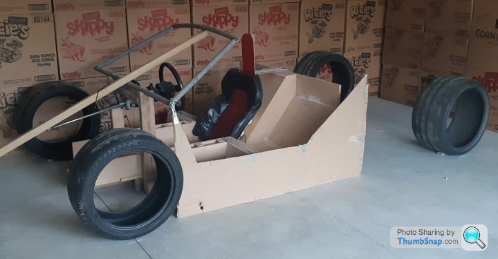
The passenger seating is really comfortable and there is ample clearance between the drivers elbows and the passenger knees, although the gear change gets really close and passengers will probably be advised to skew their legs off to the outer area of the footpanel.
No, I didn't eat all those cornflakes - the boxes will be cut into the door outer skin profiles once I have build approval from LVVTA.
The chassis is up to Version 8 - and weighs 154 kg. Total dry weight for the track mule should be just under 900kg - so am confident that I can hit the 1300kg curb weight target with bodywork.
Now that the seat size and positions are frozen I can place all the seat and seatbelt retaining bolt bosses - critical for safety as restraints and mounts have to withstand 20G loading according to NZ regulations. The door hinge sizes and positions have been determined as these are another critical item for the certifier to have calcs on.
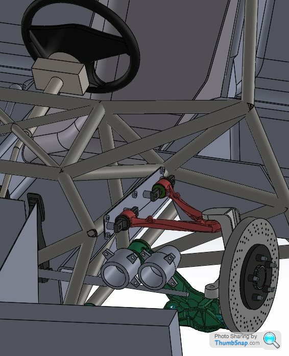
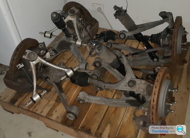
Shown above is rough detail on the CNC cut interchangeable camber and caster plates (will put some stiffening ribs between the bosses later) - these "bolt in" plates give lots of scope for fine tuning of the front end geometry without touching the chassis. Goal is to get the manual steering as light as possible while still having good straightline and heavy braking stability. The steering rack will be similarly adjustable on interchangeable plates so that bump steer is minimised.
The passenger seating is really comfortable and there is ample clearance between the drivers elbows and the passenger knees, although the gear change gets really close and passengers will probably be advised to skew their legs off to the outer area of the footpanel.
No, I didn't eat all those cornflakes - the boxes will be cut into the door outer skin profiles once I have build approval from LVVTA.
The chassis is up to Version 8 - and weighs 154 kg. Total dry weight for the track mule should be just under 900kg - so am confident that I can hit the 1300kg curb weight target with bodywork.
Now that the seat size and positions are frozen I can place all the seat and seatbelt retaining bolt bosses - critical for safety as restraints and mounts have to withstand 20G loading according to NZ regulations. The door hinge sizes and positions have been determined as these are another critical item for the certifier to have calcs on.
Shown above is rough detail on the CNC cut interchangeable camber and caster plates (will put some stiffening ribs between the bosses later) - these "bolt in" plates give lots of scope for fine tuning of the front end geometry without touching the chassis. Goal is to get the manual steering as light as possible while still having good straightline and heavy braking stability. The steering rack will be similarly adjustable on interchangeable plates so that bump steer is minimised.
Yes indeed, it is in fact impossible not to. It may look rough as guts but the buck has served it's purpose and I built it for a pittance. Money spent prototyping is always saved later in the real build.
I have had to stretch the wheelbase slightly due to the lack of late model corvette transaxles appearing on Ebay - it is now bang on 9ft (108"). When funds allow I will be stumping up for a C7 ZO6 box (TR6070) as it is the same price as the weaker C6 box. Therefore the vehicle will have a 7 speed manual gearbox, with 3 overdrives. 3 overdrives is pointless as top speed is achieved in 5th gear - but it gives me future opportunity to change the rear end ratio from the stock 3.42 to a 4.1. The C7 "e-diff" is better as it incorporates hydraulic actuation of the clutch pack, so is very easy to make on the fly changes to rear end settings during the test mule development runs - for the same outlay as a C6 unit. Also the support castings are stronger.
I have had to stretch the wheelbase slightly due to the lack of late model corvette transaxles appearing on Ebay - it is now bang on 9ft (108"). When funds allow I will be stumping up for a C7 ZO6 box (TR6070) as it is the same price as the weaker C6 box. Therefore the vehicle will have a 7 speed manual gearbox, with 3 overdrives. 3 overdrives is pointless as top speed is achieved in 5th gear - but it gives me future opportunity to change the rear end ratio from the stock 3.42 to a 4.1. The C7 "e-diff" is better as it incorporates hydraulic actuation of the clutch pack, so is very easy to make on the fly changes to rear end settings during the test mule development runs - for the same outlay as a C6 unit. Also the support castings are stronger.
Edited by F1natic on Monday 3rd February 04:39
LaurasOtherHalf said:
On nights when I can’t sleep I day (night?) dream about building something bespoke with a central driving position.
For the link to the F1 I always go back to a BMW V10 as the power plant. For no more reason than I think it’s criminal it didn’t go into anything saying much less than a two ton car!
I guess still to long with a traditional gearbox op?
What about a VW W12? It's essentially two VR6 engines and is pretty compact, and despite being a more complex beast I would have thought a Phaeton could be procured cheaply enough?For the link to the F1 I always go back to a BMW V10 as the power plant. For no more reason than I think it’s criminal it didn’t go into anything saying much less than a two ton car!
I guess still to long with a traditional gearbox op?
Then again, I like the twin engine idea and am confident you'll succeed!
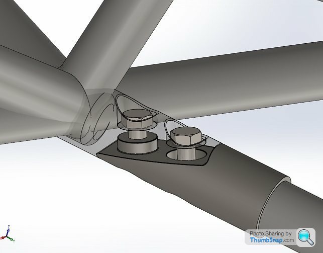
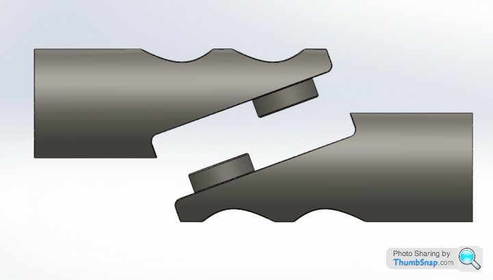
Work has continued in the background - last week I finally made a bolted joint design I was happy with between the rear engine subframe and the main spaceframe. The bolts are purely in tension, sideloads and tube torques are reacted by the matching bosses and recesses. I will 3D print a few of these and get them cast in 4130 then weld into a test setup with the 4130 tubing I am going to use and progressively load test up to yield then destruction to correlate my stress calcs with real world results.
The intention is to have the main spacefame and rear engine subframe internally pressurized with argon and monitor for cracks using a pressure sensor/gauge as porsche did with the 917. The frame will likely be painted white to make inspection of the critical junctions easy to assess during maintenance checks.
The frame configuration is frozen, just working through all the fine detail of mounting the little items, such as wiper motors, fuel fillers and vents. Thanks to some PH members input I was guided to source a Jaguar XK8 fly-off handbrake, which will help in getting into the drivers position with the handbrake applied. The exhaust tubing passes quite close to the back of the passenger bulkhead seats, so heat soak is going to be a big challenge to manage, although I won't be resorting to gold lining - more likely multilayered heat shields fed with adequate cold air. Will be nice for passengers in winter though.....
Edited by F1natic on Saturday 7th March 08:51
jase_llan said:
What about a VW W12? It's essentially two VR6 engines and is pretty compact, and despite being a more complex beast I would have thought a Phaeton could be procured cheaply enough?
Then again, I like the twin engine idea and am confident you'll succeed!
They are a great powerplant, I will have to look deeper at the compatible audi gearbox options, typically in the high horsepower ranges a manual gearbox is not an option. Cheapest W12 vehicle in NZ is $40,000 compared to $1,700 for 2 engines off the shelf.Then again, I like the twin engine idea and am confident you'll succeed!
Also it is going to be quite cost effective to modify the honda SOHC camshafts to give more lift in the VTEC upper range by grinding the base circle of the standard road cams - I am confident that 600 total engine horsepower will be achieved without turbos - and thus retain the 7L naturally aspirated engine response.
However by the time I get this project rolling under its own power it may be mandatory to have an electric motor...
F1natic said:
They are a great powerplant, I will have to look deeper at the compatible audi gearbox options, typically in the high horsepower ranges a manual gearbox is not an option. Cheapest W12 vehicle in NZ is $40,000 compared to $1,700 for 2 engines off the shelf.
Also it is going to be quite cost effective to modify the honda SOHC camshafts to give more lift in the VTEC upper range by grinding the base circle of the standard road cams - I am confident that 600 total engine horsepower will be achieved without turbos - and thus retain the 7L naturally aspirated engine response.
However by the time I get this project rolling under its own power it may be mandatory to have an electric motor...
I didn't expect the W12 cars to be so pricey over there, we can get Continental GTs in the UK for less than NZ$40,000... That certainly makes a difference! Also it is going to be quite cost effective to modify the honda SOHC camshafts to give more lift in the VTEC upper range by grinding the base circle of the standard road cams - I am confident that 600 total engine horsepower will be achieved without turbos - and thus retain the 7L naturally aspirated engine response.
However by the time I get this project rolling under its own power it may be mandatory to have an electric motor...
As for gearboxes, I'm sure an adapter plate could be made to suit the C6 gearbox, finding the correct size clutch/flywheel etc. to mate the two would be challenging though I'm sure.
As I said, I am a fan of the two engine idea anyway - two cheap, easy to work on engines is not an unrealistic way to go about things and I'd love to see it finished!
PAUL500 said:
Front screen is the only thing left to sort, Pilkington here in the UK will make one offs from a mould or will cut down an existing screen if it has a similar shape, so still researching that area.
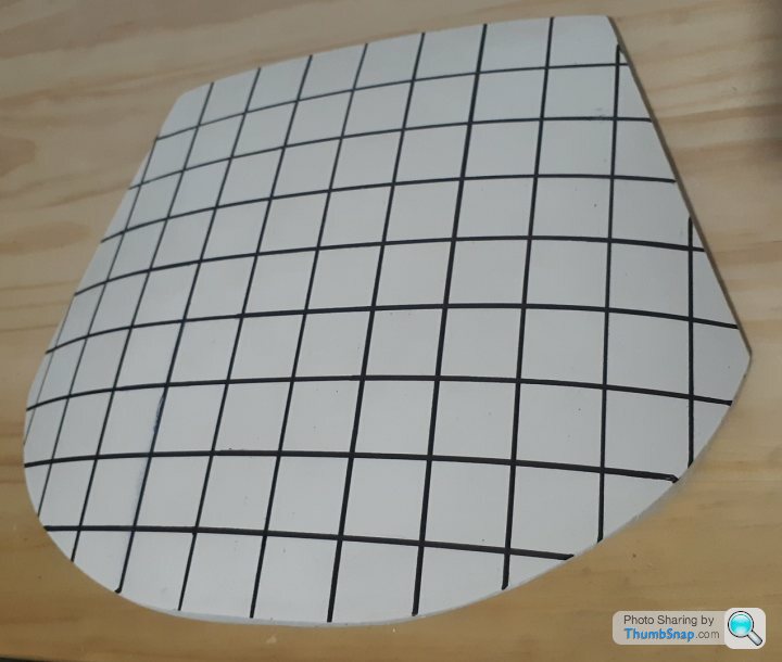
Impressive specification Paul, what do you think the torque limit for the 355 box is?I have actually pretty much given up on the idea of finding a suitable screen - the Artiplastzabrze attempt used the cutting and disguising with banding, but it looks a little "off" to my eye. Therefore have been conducting experiments in a small muffle furnace at 650C with stacked 1.75mm pieces of glass and they have formed to the contour of the stainless steel mould quite well. Have formed up to 6mm thick, but need to eliminate some small surface pock marks, currently using talc as the release agent so going to try boron nitride next. Once the pocking is resolved I will be moving to larger scale tests and then need to find someone with an autoclave to do the PVB lamination tests (145C at 10 bar).

Also have CNC cut a 1/10 scale female mould in polystyrene foam and cast a plaster of paris plug, the contours feel nice.
New Zealand, much like the rest of the world, has gone into lock down. Over the next 4 weeks, if I stay healthy, plan to bang out the interior detail. Fortunate that I can work from home and thus have brought a 3D printer home. The distraction from the outside world events will be welcome.
Good luck to everyone, it is a s
 tty hand we have been dealt, hope you can make the most of it.
Edited by F1natic on Tuesday 24th March 10:50
The upper limits of the 355 box have never really been tested, as even competition 355s do not produce a great deal more than stock power anyway.
The limiting factor was the propeller shaft and dual mass flywheel, both of which have now been uprated, a chap who competes with one told me they no longer worry about gearbox problems.
There was a powerful hillclimb car with a zytec engine but I believe that used the matching non Ferrari sequential race gearbox.
I had heard the 5 speed version of the Ferrari box as fitted in the earlier 348 was a stronger box.
The 575 engine will be the test bed for our box, if it survives that then its good to go for any further project.
We need to finish the current build before any real work goes into the next, so yours will be long done by then so you will have already resolved the screen matter as well
Edited by PAUL500 on Tuesday 24th March 20:03
Gassing Station | Readers' Cars | Top of Page | What's New | My Stuff