540HP NA 7L V12 3 seater
Discussion


F1natic said:
threadlock said:
for pulling away I'd have thought any mis-match in the bite-point and the engaged engine would spin up wildly through the disconnected clutch before the second clutch engages. You'd get no drive to the wheels until both are engaged.
Sorry, but thats not how the mechanism works. Lets say we have selected 1st gear and both clutches are in, as the clutches are released you are right , inevitably one clutch will bite before the other, however the crownwheel between the pinions prevents "crosstalk" between the engines. One pinion cannot spin the other with out spinning the drive output, which is connected to the road wheels. There is no differential movement in this setup, plus I have built it in lego so I know it works!Edited by F1natic on Friday 3rd April 10:35
stevesingo said:
In my mind I see that when pulling away from a stand still (if there is a mis-match in engagement), one clutch would start transferring drive to the pinion, which should start the car moving. If any throttle is applied, the second engine revs will rise until such a point where the clutch starts to transfer torque. This might be difficult to control.
You are utterly correct, and it is not a condition I had considered enough, thanks for your post. I was expecting to be dropping both clutches rapidly almost everywhere all the time.... Any throttle during moving off could cause a rev rise on the unloaded engine and could wear/glaze the clutch prematurely. I had to go out and drive around in my old manual car, checking the timing of the clutch release and bite point position. On the level the standard technique for a Mclaren F1 would be best (https://youtu.be/nk3DGaZ529E?t=117) as the engine torque even at idle is enough to get the car rolling. Using a pair of standard roadcar engines gives much greater flywheel effect compared to the f1, so would be an advantage in the "moving off without throttle" situation.
Aluminium flywheels on drysumped race engines are on my future upgrade list if the Tbox works, but using the stock dual mass flywheels will prolong the life of the Tbox gears enough for me to get some development miles on the chassis while I build the bodywork. If the Tbox turns out to be as tough as I expect then converting over to less damping for the sake of throttle response is part of the long term plan.
If the rev rise on unloaded engine is an issue during testing (and hill starts are when this issue would be obvious) I may have to put an extra idle adjustment feature into each ECU so if "zero road speed" and "clutch engaged" and "handbrake on" are detected the idle air valve opens to give a high idle (tunable from the drivers seat with a pot) so that the "loose " engine is prevented from revving up too much. It would almost act like an anti-stall. Once the clutch is fully released or road speed is above zero or the handbrake is off then high idle would be disabled. Trickling along in heavy stop start traffic is a good example of high clutch use and the tunable idle may be very useful for matching variable road conditions, although I must keep the system as simple as possible in the first iteration. It may seem counterintuitive but lightly applying the handbrake (enough to operate the switch but not the brake) could help the car move off smoothly in stop start. Interesting optionthat I had never considered, thanks!
Edited by F1natic on Saturday 4th April 09:13
There are two options for me;
1, Mechanical: Use a balance bar on the clutch pedal to equalise clutch actuation.
2, Electronic:
A-When wheel speed is <10kph, set a target rpm against throttle pedal demand. 0kph 3% pedal demand = 1200rpm. If one clutch engages earlier, more throttle applied to hit target 1200rpm as an example.
Or both.
Penguinracer said:
As a fellow Kiwi who's been based in the UK for almost 25 years - it always warms my heart to see guys back home in sheds taking on ambitious projects in economical ways.
Thanks mate! I recommend reading Patrick Harlows' book on NZ manufactured cars - you will be amazed at some of the projects that he uncovered - ISBN 978-1-877427-51-0 

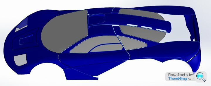
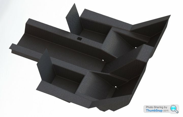
After looking long and hard at a range of photos I have settled on the roadcar nose - easy to modify afterwards for a racing version. The first iteration is a roadcar so that decided it for me. The shell (4mm thick) in polyester resin with proper thickness glazing is 116 kg as shown, but there is a lot of detail and therefore weight missing. Moving onto the interior now.
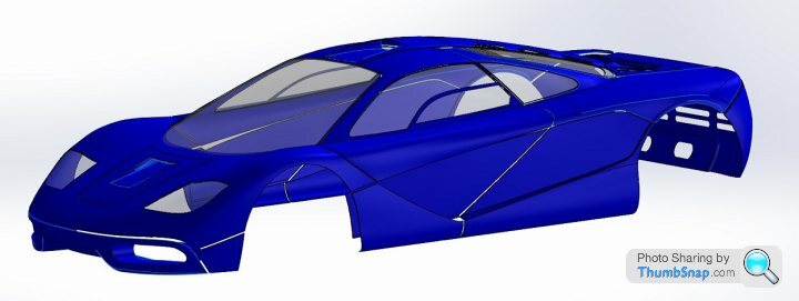
XP6 is born!
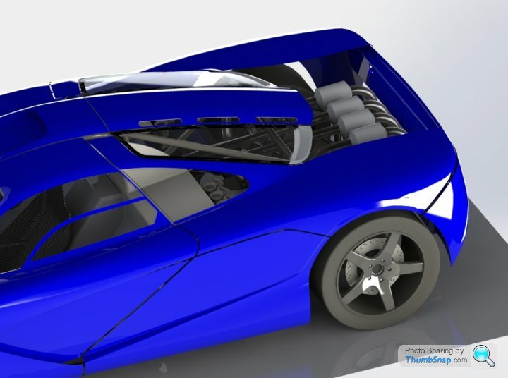
The frunk volume is 4 cubic feet (approx 112l) - enough for soft luggage. The brake and clutch reservoirs are accessible behind a panel on the firewall.
Still working on the Interior - I may be some time.....
Also working through the final checklist on legal requirements for road certification - hence things like the front indicators have now been modelled using Hella 2168 units. All the signal lighting will be modern LED type.


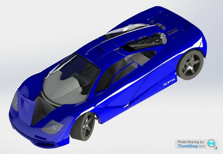
What a wormhole the LVVTA 175-00(03) seatbelt anchorage regulations can be. The seatbelt lug points will penetrate the interior panelling, shown as cutouts in the carbon fibre tub below, therefore attaching the seatbelts directly to the 4130 steel spaceframe. The rule is each lug has to be at the intersection point of a minimum of 2 tubes. Lots of iterations involved in getting those in place efficiently.
To make certification for the road as easy as possible I have followed the well troden path of a steel spaceframe with lightweight (i.e thin and non structural) carbon fibre diapraghm panels, such as the tub component. However these panels will boost the chassis stiffness, but they are mainly there as bling and to stop my legs poking out of the gaps in the frame.
Final fuel tank sizing will be 60L, good enough for a crusing range of 500km and maybe 100km of "enthusiastic" driving. There is space for an optional pair of auxilary long range tanks which could comfortably take capacity up to 90L. The certifier demanded a flanged design with lots of internal baffling and that the tank be retained by strapping, so best option is from 1.6mm thick aluminium sheet.
The Center of Mass only shifts a few mm with fuel load and passengers, going into the detail analysis has made me appreciate how clever the original design is.
Edited by F1natic on Monday 27th April 00:35

From this angle you can see the passenger shoulder retractor slots clearly.
The pedals themseves are going to be custom made with a pedal ratio of between 6-7 and using Tilton remote reservoir & 75 series master cylinders in a dual circuit layout with a tilton balance bar assembly allowing f/r balance once track testing starts. The reservior is positioned higher than all the caliper bleed nipples.
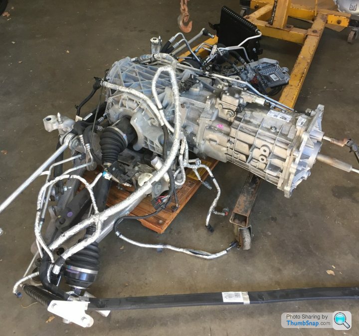
Photo of the newest acquisition for the project - an MEK transaxle from a C7 Z06 with a torque limit of 860nm. It is fairly obvious from this shot why the weight distribution of the car is at 45F/55R, the rear axle is a long way from the input shaft. By nature of their transverse position both engine bellhousings nestle in nicely to the transmission front mounting plate. I needed a real sample to reverse engineer from so that the CAD models could be completed - photos and internet info are not good enough for this task.
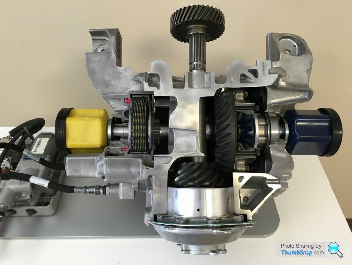
These units have an electronically controlled differential that can change from open condition to locked (0 to 100%) in 150 ms (.15 sec) . The diff when locked up to 100% corresponds to 2000 Newton-meters (1475 ft-lbs) of break-away torque (every 1% is 20 Nm (14.75 ft-lbs)). So at full lock it would take 2000 Nm of torque between the wheels to make the clutches slip. For reference a C6 Corvette mechanical differential clutch pack has around 120 Nm (88 ft-lbs).
Being able to tune the open setting on corner entry allows easy influence of the rate of yaw – what GM term Yaw Damping. Given how centralised the masses are the low polar moment of inertia could take a bit of getting used too – during the initial testing the diff can be set higher to give less snappy and responsive turn in – it will have tunable understeer. The advantage is a few laps later you can tweak the setting from the drivers seat to what feels best.
When heavily on the throttle, the diff can lock up more and shift torque from the inside wheel to the outside wheel. This has the combined effect of minimizing or eliminating inside wheel spin, but it also controls how much it feels like the car turns with the throttle.
Here is a cutaway showing the diff internals, the hydraulic pump on the left pressurizes a piston that clamps the clutch plates - no springs required.
Edited by F1natic on Saturday 16th May 08:56
Mr Natic ,
Great project , in case it helps,here's a pair of straight 6's running 45 degrees offset ,with and without silencing ,..to give you an idea of the sound with that degree split .
https://www.youtube.com/watch?v=x0hdoMj1lDU&t=...
regards
robert
Great project , in case it helps,here's a pair of straight 6's running 45 degrees offset ,with and without silencing ,..to give you an idea of the sound with that degree split .
https://www.youtube.com/watch?v=x0hdoMj1lDU&t=...
regards
robert
F1natic said:
You are utterly correct, and it is not a condition I had considered enough, thanks for your post. I was expecting to be dropping both clutches rapidly almost everywhere all the time....
Any throttle during moving off could cause a rev rise on the unloaded engine and could wear/glaze the clutch prematurely. I had to go out and drive around in my old manual car, checking the timing of the clutch release and bite point position. On the level the standard technique for a Mclaren F1 would be best (https://youtu.be/nk3DGaZ529E?t=117) as the engine torque even at idle is enough to get the car rolling. Using a pair of standard roadcar engines gives much greater flywheel effect compared to the f1, so would be an advantage in the "moving off without throttle" situation.
Aluminium flywheels on drysumped race engines are on my future upgrade list if the Tbox works, but using the stock dual mass flywheels will prolong the life of the Tbox gears enough for me to get some development miles on the chassis while I build the bodywork. If the Tbox turns out to be as tough as I expect then converting over to less damping for the sake of throttle response is part of the long term plan.
If the rev rise on unloaded engine is an issue during testing (and hill starts are when this issue would be obvious) I may have to put an extra idle adjustment feature into each ECU so if "zero road speed" and "clutch engaged" and "handbrake on" are detected the idle air valve opens to give a high idle (tunable from the drivers seat with a pot) so that the "loose " engine is prevented from revving up too much. It would almost act like an anti-stall. Once the clutch is fully released or road speed is above zero or the handbrake is off then high idle would be disabled. Trickling along in heavy stop start traffic is a good example of high clutch use and the tunable idle may be very useful for matching variable road conditions, although I must keep the system as simple as possible in the first iteration. It may seem counterintuitive but lightly applying the handbrake (enough to operate the switch but not the brake) could help the car move off smoothly in stop start. Interesting optionthat I had never considered, thanks!
Why not remove the clutch's from the engines and then add a single one to the gearbox?
Edited by F1natic on Saturday 4th April 09:13
sheepdip said:
Why not remove the clutch's from the engines and then add a single one to the gearbox?
A good question Sheepdip, that way would be simpler mechanically. However I have 3 main reasons for not going that way;1) Packaging - I am really struggling to cram everything into the short wheelbase as it is, and the clutch inline with the transaxle would add more length forcing the rear wheels back. Currently the dual mass flywheels and standard honda clutches fit nicely into the area where the support bearing housing for the pinions reside, its now quite compact and robust
2) Harmonics - I do not want to direct couple the crankshafts using gears as I have seen some twin engine attempts where crankshaft oscilations due to the power strokes literally smash the gear teeth to pieces, having the dual mass flywheel on each engine insulates the pinions from those distructive angular oscillations.
3) I really want to be able to switch off one engine at will. With the weight at approx 1350kg and clean aerodynamics and now a 7 speed gear box with 3 overdive ratios the power required to cruise at the speed limit will be low - so fuel economy should be minimised. I don't need a 7L engine for the majority of use and even though I am lugging around an extra 150 kilos - when the road and traffic conditions suit I can bring the suspended motor into play and consume all the fuel I had been saving earlier! It will be like having a large passenger who can pedal very hard when asked too.
Edited by F1natic on Monday 4th May 01:11
ivanhoew said:
Mr Natic ,
Great project , in case it helps,here's a pair of straight 6's running 45 degrees offset ,with and without silencing ,..to give you an idea of the sound with that degree split .
https://www.youtube.com/watch?v=x0hdoMj1lDU&t=...
regards
robert
Robert, your project is exemplary. Also your videos are great, thanks for the link, looks like you are having a lot of fun now that she is under her own power. I will probably do the same dance when I get my setup running for the first time too. In all my years of searching the internet for twin engine setups I still managed to miss an epic project such as yours.Great project , in case it helps,here's a pair of straight 6's running 45 degrees offset ,with and without silencing ,..to give you an idea of the sound with that degree split .
https://www.youtube.com/watch?v=x0hdoMj1lDU&t=...
regards
robert
If anyone knows of any other successful twin engine projects (or failures, they are more informative!), I am always very interested to know the technical details.
Edited by F1natic on Monday 4th May 07:25
Gassing Station | Readers' Cars | Top of Page | What's New | My Stuff