540HP NA 7L V12 3 seater
Discussion


MrBig said:
I wish I was in a position to contribute like others have on here, but really all I've got is to say this is fascinating reading and please keep going!! Can't wait to see more parts come to life!
Thanks Mr Big, voicing your encouragement is greatly appreciated. The CAD work has turned out to be more of a slog than I expected so if my descent into madness is providing a little bit of entertainment then that is a good result.It is very easy to fall into a mindset, for example have been struggling to find room to increase the capacity of the fuel tank while retaining the ability to drop it straight out of the frame if servicing is required. Completely missed that going to dry sumps allows me to move around a few tubes around the tank and has increased the volume possible to ~ 80L.
F1natic said:
MrBig said:
I wish I was in a position to contribute like others have on here, but really all I've got is to say this is fascinating reading and please keep going!! Can't wait to see more parts come to life!
Thanks Mr Big, voicing your encouragement is greatly appreciated. The CAD work has turned out to be more of a slog than I expected so if my descent into madness is providing a little bit of entertainment then that is a good result.It is very easy to fall into a mindset, for example have been struggling to find room to increase the capacity of the fuel tank while retaining the ability to drop it straight out of the frame if servicing is required. Completely missed that going to dry sumps allows me to move around a few tubes around the tank and has increased the volume possible to ~ 80L.
Edited by Caddyshack on Saturday 20th March 08:36
threadlock said:
F1natic said:
Thanks Mr Big, voicing your encouragement is greatly appreciated.
I'm another of the silent majority watching the story unfold. It's really interesting - please never think your updates aren't appreciated or seen by many!Caddyshack said:
What are your productions plans, I.e. with that fuel tank for example, will you fabricate it yourself or give to a firm to do? It is worth adding a small sump at the bottom, about the size of a baked bean tin with some holes in the top to reduce slosh and then have your drain hole and fuel pick up from there as then the last drops of fuel always end up there and won’t starve.
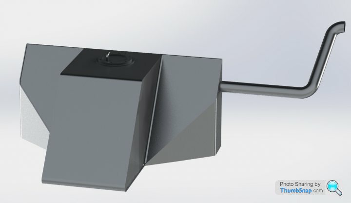
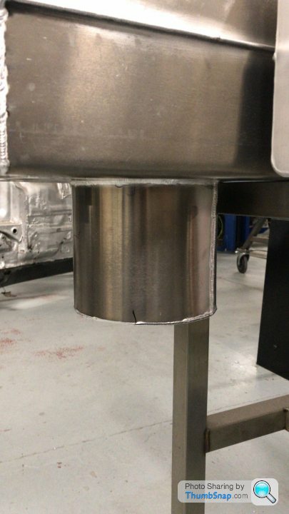
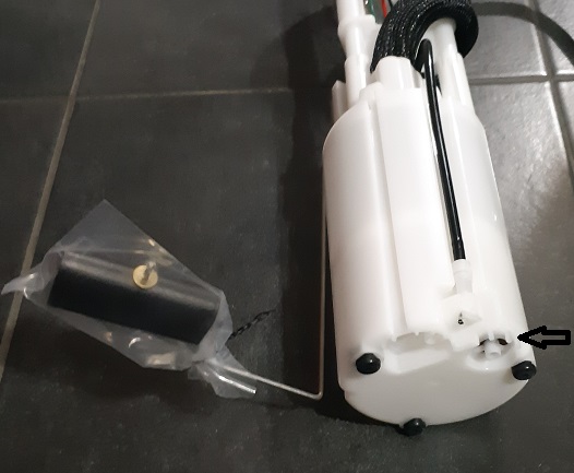
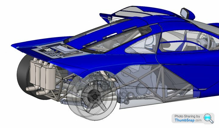
Due to my modest budget I am doing the fabrication myself. The test engine fire up will require a dummy tank to mount the fuel pump, so a good time to get TIG practice in. Will be getting "Bessie", a 1984 Mazak AJV25-404 to mill out some plate to form the pump retaining collars. The outer skins are folded from sheet and flanged using my Lagavulin flypress (so named as it was traded for a bottle). A good point about the fuel sump. The corvette pump is useful in creating a low profile tank as it has its own fuel sump built in, the venturi pump inlet shown below sucks the dregs out of the tank and ensures that the pump is covered in fuel and remains cooled even when the tank is mostly fumes. Any fuel that bypasses the pressure regulator also drops back into this sump
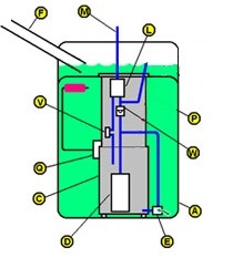
C = pump sump
D = Fuel pump
E = Venturi pump driven from main pump outlet
L = Filter
W = non return valve
V = pressure regulator
The part shown is an ULTRA-POWER E4013M for 67 quid, so a bit of a bargain for all it does.
Just working out the swing of the fuel sender so that it clears the internal baffles plates.
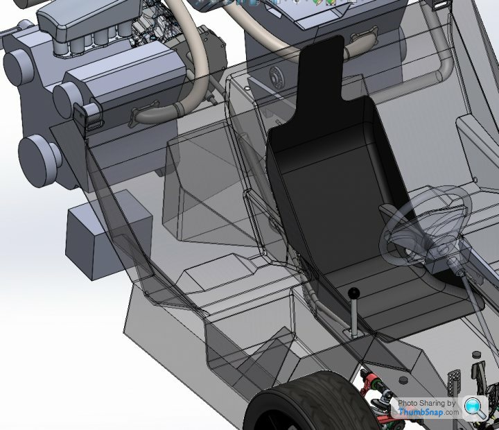
The raw mesh of the trans assembly did not require scaling, the kinect scanner determined the size by ranging the surfaces as it went. The light grey box is the original design envelope roughed out for the gearbox based on measures from real parts, however it is good to see close alignment between virtual and real data. The 2 little cylinders under the centre of the gearbox are the transmission isolation mount faces, didn't have any UNC nuts to attached the real parts for the scan, but vernier measures are reliable enough for now. Once the build approval is given will lay all the big parts out in true scale according to the CAD positions and double check anyway.
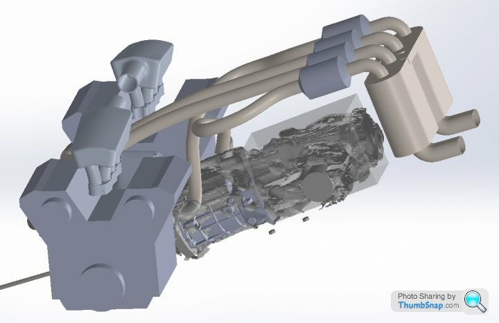
Engine scan next.
Engine scan next.
Just a couple of handy hints
The oil level sensor, Peugeot 306 have an oil level gauge that indicates oil level before engine start up.
Dry sump pump, I have actually done this on my racecar, I run the dry sump pump of the 4pk water pump belt BUT the dry sump pump only pre charges the original engine oil pump, thus it doesn't create the engine oil pressure. The scavenge side works as it usually does in a dry sump installation, but the pressure side only supplies the standard engine oil pump ( I wound the pressure relief valve way out). it all works just fine, I simply made a fitting onto where the standard oil pick up bolts onto the bottom of the block/timing cover and ran a hose through the dry sump to another bulkhead fitting in the side of the dry sump where the output from the pressure pump feeds to.
Best of luck with your endeavour.
My old CAD workstation at home died suddenly - very frustrating event and time consuming to get back to normal operations.
The scanning of the test engine went very well, and once the main axis of the point cloud was superimposed over the original CAD block model the result was quite acceptable. The exhaust manifolds lined up quite close to the target areas.
The white area in the middle of the vee is the true gap between the inlet castings. The mesh is really quite detailed, however obtaining still shots that don't look rubbish is proving challenging - so I am not going to waste anymore time trying. The mesh looks great rotating in the dynamic view as the features on the block are easily perceived. The scanner was the best $2 I have ever spent.
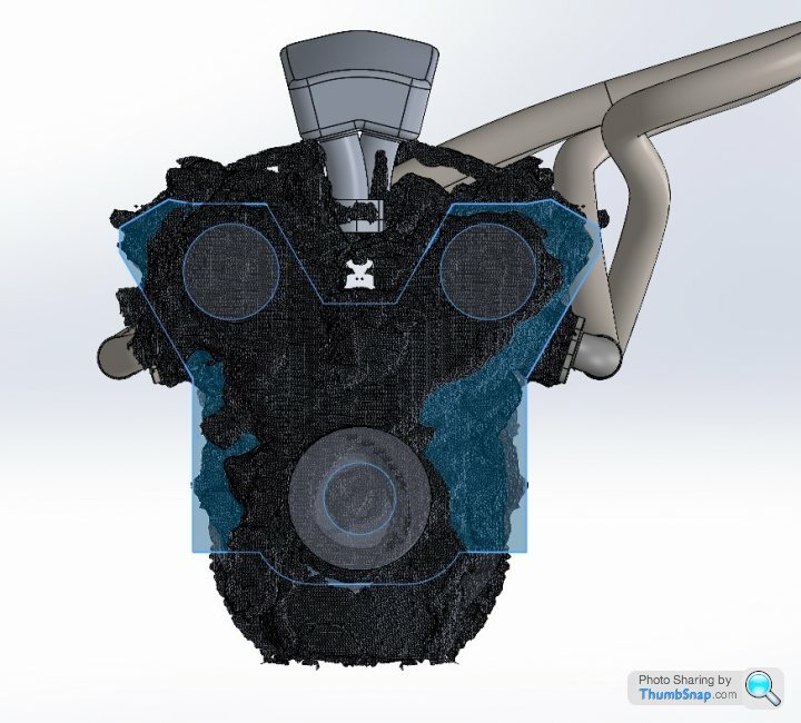
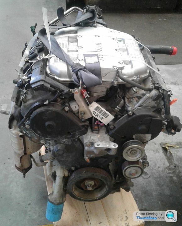
A shot of the standard engine assembly - scan has parts removed i.e. plenum, cats, thermostat housing and hoses
The scanning of the test engine went very well, and once the main axis of the point cloud was superimposed over the original CAD block model the result was quite acceptable. The exhaust manifolds lined up quite close to the target areas.
The white area in the middle of the vee is the true gap between the inlet castings. The mesh is really quite detailed, however obtaining still shots that don't look rubbish is proving challenging - so I am not going to waste anymore time trying. The mesh looks great rotating in the dynamic view as the features on the block are easily perceived. The scanner was the best $2 I have ever spent.
A shot of the standard engine assembly - scan has parts removed i.e. plenum, cats, thermostat housing and hoses
Edited by F1natic on Saturday 29th May 10:52
There is light at the end of the tunnel as far as the paperwork goes - double checking all the sub-assemblies and part details takes time though. Since I am only doing this the once I want to ensure that I clean up the niggly details I was leaving till the end - which is the suspension mostly. All the fun of being behind the computer is gone and it is a real slog when solidworks keeps crashing - the issue stems from using configurations within configurations within configurations (bit like the movie Inception, even the computer loses track of where the story is up to). Using up the last of the gumption reserves and looking forward to sending off the approval document. Hopefully all this extra time spent in the layout phase pays back 10 fold when it comes time to fabricating and assembling, and certification will hopefully just be a rubberstamping exercise.
Comparison shot of the C6 corvette stock geometry as modelled plus the F1 both in full rebound, with a C7 for reference.
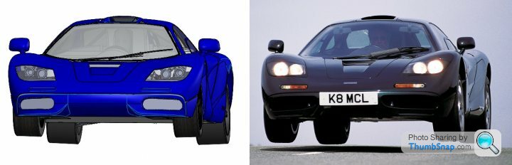
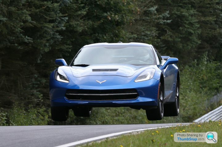
Comparison shot of the C6 corvette stock geometry as modelled plus the F1 both in full rebound, with a C7 for reference.
Edited by F1natic on Monday 26th April 07:15

Been quite stuck over the last few weeks trying to overcome a glaring brain fart in the detail design of the gearchange mechanism. Since the early ergonomic layout 18 months ago I had not fully appreciated how the engine rocking on the mounts would cause a significant change in the position of the selector shaft on the transaxle relative to the "fixed" shafts connected to the body. Originally I was intending to arrange the mounts so that the selector was on the pivot axis, however other constraints resulted in the transaxle selector moving in an arc centered on the low axis formed through the central Tbox mount and the pair of transmission mounts. Movement of the selector will be no more than +/- 3mm side to side, and the new gearshift shafts position and angles should not affect the gear engagement. Now the design has a tube passing through the fuel tank (clears the repositioned fuel pump) to allow a direct shot to the selector as there was no way to route around the tank. Not sure how the LVVTA will accept this idea, but as the whole concept is fairly unconventional and wacky - why stop now!
Would appreciate a bit of guidance/input as to what people think is the best manual shifting gearbox and throw angle. I have measured the angles directly from the TR6070 selector shaft and they are not even, although the weighting of the detents across the 4 gates is very distinctive. The test mule will be adjustable by changing the distance between the gearstick and selector centrelines, but was thinking of starting off with around the 9 degrees that Gordon Murray used for the F1 (and will be used for the T50).
This layout sketch shows the position of the gear knob with 1-2 gate on the left.
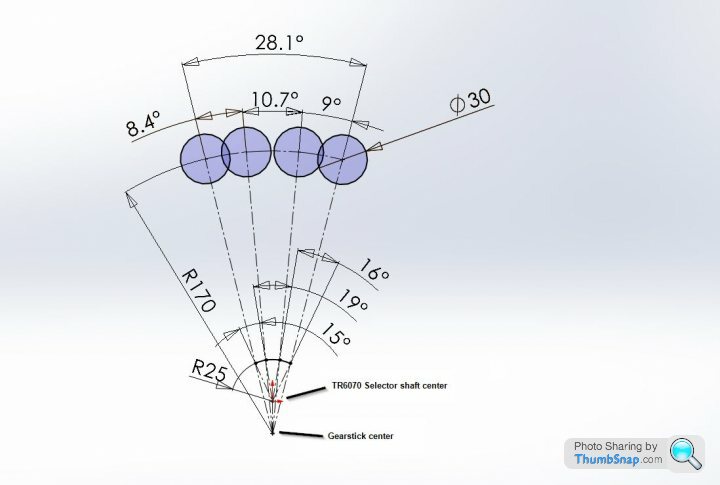
This layout sketch shows the position of the gear knob with 1-2 gate on the left.
LaurasOtherHalf said:
I don’t have the diagram, but my civic type r which replicated the nsx type r at 40mm was perfect for me.
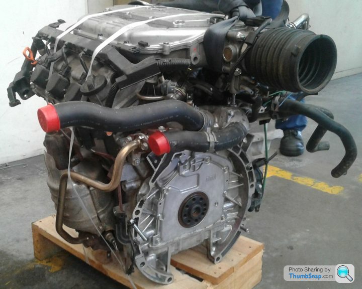
Thanks, that is a good starting point - will test it early on with the "proper" seating buck once build approval is checked off.Have come up against a really ugly problem, the scavenge pumps should be on the "downwind" side of the sump pan so that windage drives the oil into the outlet ports. Positioning the pump on the appropriate side (as shown below) unfortunately results in the drive belt clashing with the standard oil filter placement (see photo of standard engine a few posts above). Stink. The goal was to keep the engines stock "off the shelf" units, but this is looking unlikely now.
Battery, alternator and starter motor are all on the right flank which means the right motor is the primary engine. The wiring is being kept as short as physically possible. Given the fuel filler (and overflow) are on the left flank the idea was also to keep electrical and fuel systems separated as far as practical for added safety.
Need to complete modelling the suspension pickup brackets, drive shafts, dry sump tanks and engine nose mounts. The stock nose mount bolts onto the block above the harmonic balancer, will have to make a custom mount that suits easy removal of the subframe.
Thinking the rear deck lid will have to be made out of aluminium, since it is adjacent the cats and there will not be any gold plating on this car so unprotected composites will cook.
I just missed the cutoff for the June Technical Advisory Committee, so paperwork is going in next week so its at the head of the queue for the next meeting first Tuesday of July. While I wait for their feedback (and changes probably) I will be working on the ECU wiring and test engine fireup while also building the proper seating buck as the frame can always be adjusted to suit the most comfortable dimensions - the mark 1 cardboard buck was just ballparking, next one is for taking moulds from. The gearbox linkage is a very important factor in the driving experience so will be mocking up the system with the transaxle sitting in the correct position as per the CAD model. Its been a longer design phase than hoped for, but as expenditure limits apply the build will be slow anyway.
Edited by F1natic on Sunday 30th May 06:52
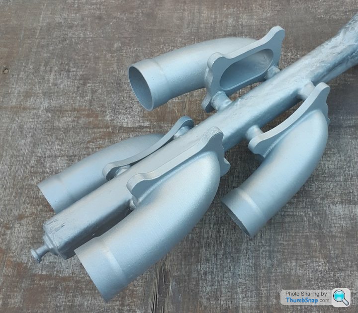
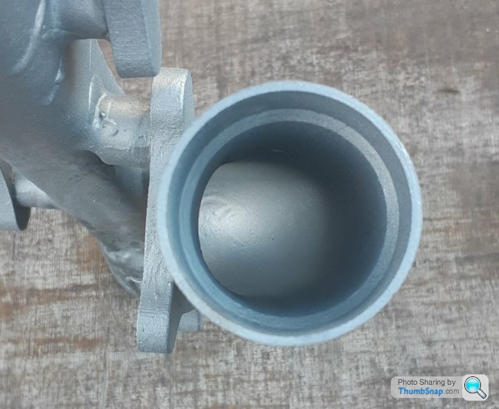
Good result today for the exhaust stub prototypes, they are off to heat treating tomorrow then machining. 2 of them should be bolted onto the primary test engine in a few weeks. The mice are going to have to get their sunglasses out as flames are coming soon......
Edited by F1natic on Monday 31st May 05:25
Gassing Station | Readers' Cars | Top of Page | What's New | My Stuff