540HP NA 7L V12 3 seater
Discussion


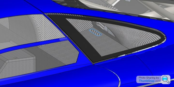
In light of the "inadequate" exit air vent sizing of the original design (as discussed during the T50 reveal) have decided to locate a large vent by the rear cabin window. The fan drawing air out of the cabin will be plumbed to exhaust air into the heatshield airgap to help prevent cooking the passengers kidneys.
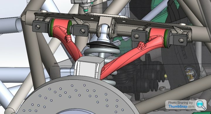
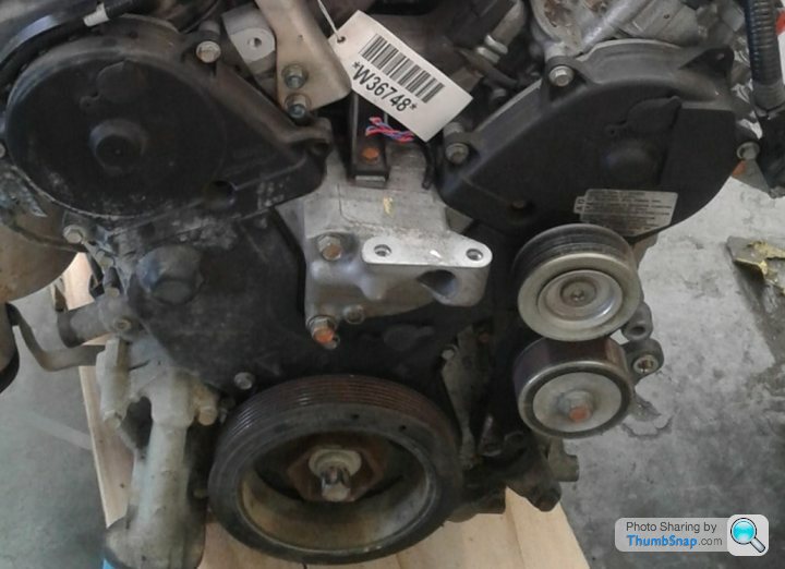
Back on page 6 of this thread I roughed out the UCA mounting plate, but have now developed the idea a bit further. The UCA mount plate is a bolt on part that allows quick and easy swap out to allow experimentation on the test mule settings for caster, camber and antidive angles on the front suspension. The shock loads transfer directly into a backing plate that is welded to the chassis tubing. The mount plate also stiffens the control arm chassis tube by acting like a huge gusset. It is also another part that has been designed to be 3D printed and cast. The outer most end bolts go through crush tubes welded into the chassis tubing, the tops of which can just been seen.
Psycho Warren said:
I have just got my first 3D printer so will be experimenting on it for various parts, brackets and also "patterns" for composite moulding on my single seater project.
Brilliant idea, do you have a link to a build log for your project? I would be keen to look over your shoulder on that one.We use PLA for our 3D printed patterns as it burns out well and the fumes it gives off while printing are not bad, however have tried ABS as a mould material as the tooling can be acetone smoothed which saves lots of manual work polishing the internal cavities, however you have to be careful with the exposure time or dimensional accuracy can suffer, depends utterly on the part you are making. I have not had the opportunity to try dry ice blasting, but it looks like a really good surface prep method.
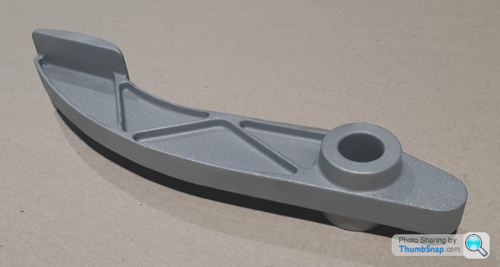
CAD model said weight would be 933 grams, casting has come out at 948. Now that the part is actually in my hands it makes me realise that every gram counts and this is overkill compared to the Tilton forged aluminium pedal. I have realised that "just because you can doesn't mean you should", the 3D printed pattern was so light that I sucked myself in a bit. Really happy with the result, but in reality it won't be going on the test mule as the off the shelf solution will be easier to get through compliance and is lighter.
Paperwork is in. I noticed the first entry in my design journal for the project was 1/7/2011 - feels like 10 years has gone by in a blink. Currently designing the build table while awaiting feedback from the next TAC meeting on 3rd August. In the last 18 months there have been no requests for technical variations from the rule book, this project requires 5 - so will have to see how that pans out!
Also reverse engineering the nose mount for the engines, put the part up on the CMM tonight as the timing belt covers have to fit perfectly around the flanged edge. The block out model is a bit too simple currently and needs fleshing out.
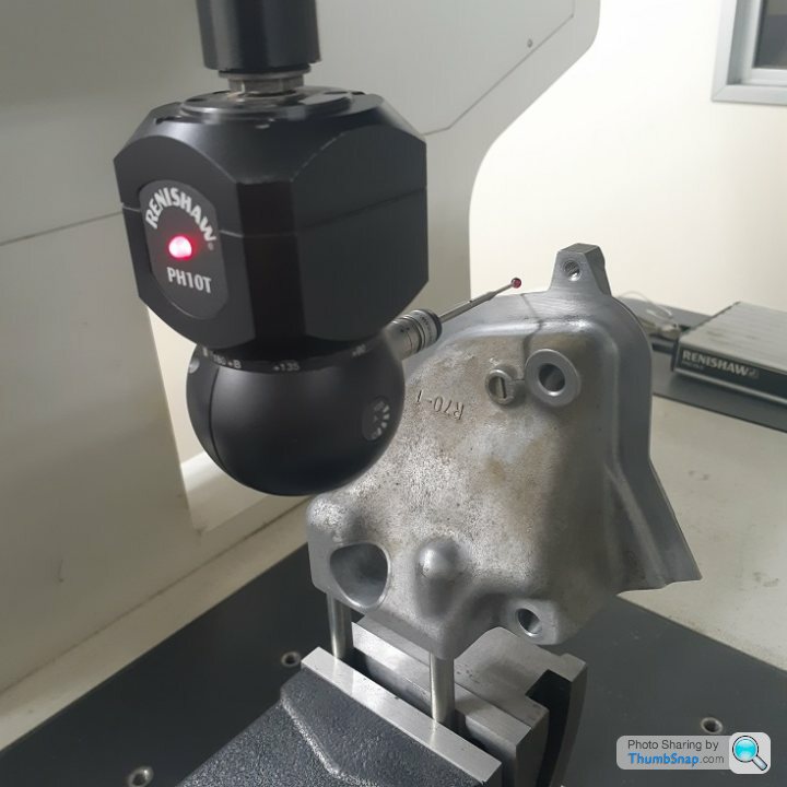
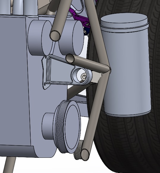
Also reverse engineering the nose mount for the engines, put the part up on the CMM tonight as the timing belt covers have to fit perfectly around the flanged edge. The block out model is a bit too simple currently and needs fleshing out.
LVVTA paperwork is back and approved, with a strong recommendation to use certified glazing. That is going to be a difficult task given nothing to date is even close in size or shape, however that hurdle is a long way in the future with plenty of short term challenges to work through beforehand.
Next major milestone is constructing the fuel tank and test engine rig so that the Speeduino ECU can be setup. The J35Z2 has a unique code pattern for the cam signal (back on page 10 - a year ago!) so getting the engine to run on sequential fuel will require more brainpower than I currently have. Initially it should run just fine on batch fire as that only requires synchronisation with the crank signal, which is a high resolution 60-2 tooth pattern.
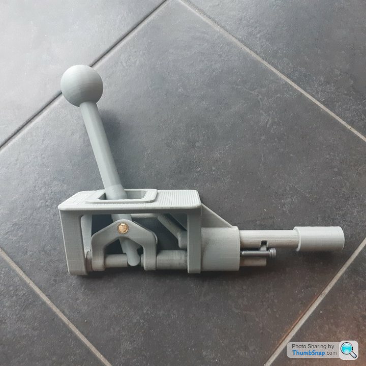
Next minor milestone is to complete a proper interior buck so that the door hinge system can be tested. Due to the fact that I never want to be trapped in an inverted vehicle with dihedral doors I have been given a concession on the hinge design rules to allow removeable hinge pins, released by a lever inside the cabin (positioned such that it cannot be inadvertently operated by a passenger).
Picked up the steel for the build table, start cutting that this weekend. Need lots of little welding jobs to practice on before starting on the spaceframe though. The certification process requires tack welding all the tubing in place so that the certifier can inspect all the fitting gaps BEFORE full welding is done - it's a good test of workmanship.
Plenty of tasks to knock off on the road to the test mule, which the TAC agreed was a good way to test the very complex design before building the road car from it.
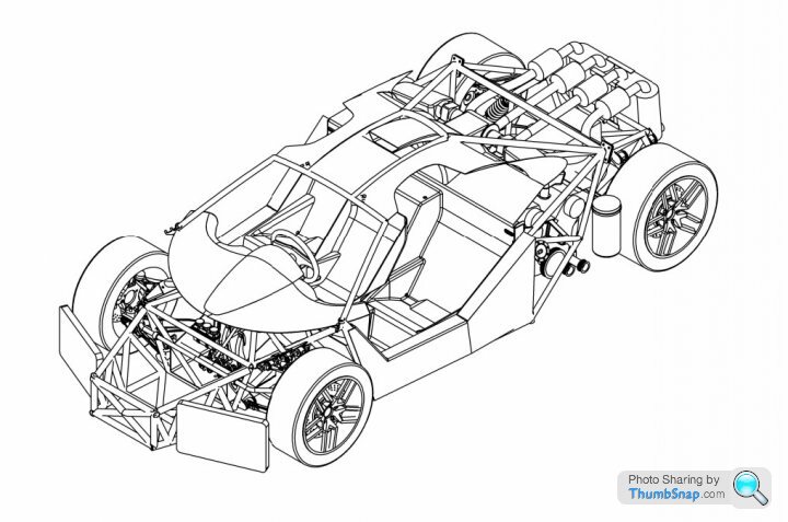
Part of the approval process was specifying the wheel and tire combo, shown are the standard Corvette C7 Z51 rims I have settled on - tires will be some form of Michelin.
Next major milestone is constructing the fuel tank and test engine rig so that the Speeduino ECU can be setup. The J35Z2 has a unique code pattern for the cam signal (back on page 10 - a year ago!) so getting the engine to run on sequential fuel will require more brainpower than I currently have. Initially it should run just fine on batch fire as that only requires synchronisation with the crank signal, which is a high resolution 60-2 tooth pattern.
Next minor milestone is to complete a proper interior buck so that the door hinge system can be tested. Due to the fact that I never want to be trapped in an inverted vehicle with dihedral doors I have been given a concession on the hinge design rules to allow removeable hinge pins, released by a lever inside the cabin (positioned such that it cannot be inadvertently operated by a passenger).
Picked up the steel for the build table, start cutting that this weekend. Need lots of little welding jobs to practice on before starting on the spaceframe though. The certification process requires tack welding all the tubing in place so that the certifier can inspect all the fitting gaps BEFORE full welding is done - it's a good test of workmanship.
Plenty of tasks to knock off on the road to the test mule, which the TAC agreed was a good way to test the very complex design before building the road car from it.
Part of the approval process was specifying the wheel and tire combo, shown are the standard Corvette C7 Z51 rims I have settled on - tires will be some form of Michelin.
I have been following this thread with interest and really admire the ops approach of designing everything prior to fabrication.
When you compare it to something like project binky for example. As great as those guys are they have modifying parts they have already made and changing things through the build. Admittedly the results are stunning though.
On this project once everything is deigned I would imagine the fabrication and assembly part of the build won’t be too long. (Providing the required finances are in place)
robemcdonald said:
I have been following this thread with interest and really admire the ops approach of designing everything prior to fabrication.
When you compare it to something like project binky for example. As great as those guys are they have modifying parts they have already made and changing things through the build. Admittedly the results are stunning though.
On this project once everything is deigned I would imagine the fabrication and assembly part of the build won’t be too long. (Providing the required finances are in place)
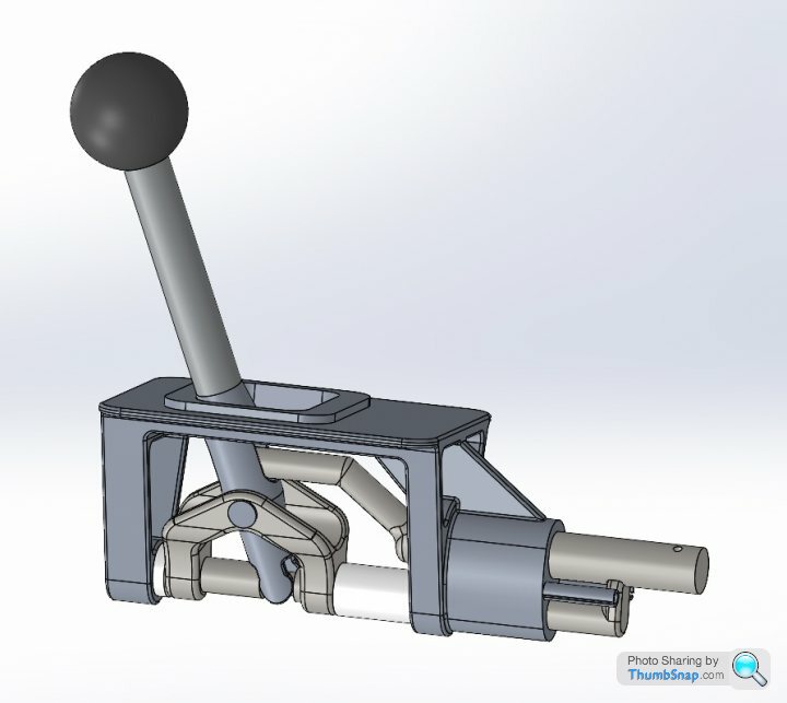
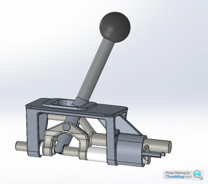
Is design like this fool proof though? I imagine there is a lot of modification as you go with the build hence big manufacturers having test mules and I would guess that the design of this type cannot know that you can't get to X bolt to hold in the gear selector or the exhaust cannot pass something etc. When you compare it to something like project binky for example. As great as those guys are they have modifying parts they have already made and changing things through the build. Admittedly the results are stunning though.
On this project once everything is deigned I would imagine the fabrication and assembly part of the build won’t be too long. (Providing the required finances are in place)

Caddyshack said:
Is design like this fool proof though? I imagine there is a lot of modification as you go with the build hence big manufacturers having test mules and I would guess that the design of this type cannot know that you can't get to X bolt to hold in the gear selector or the exhaust cannot pass something etc.
Absolutely Caddyshack, no way is CAD a foolproof method. Often having the real parts in front of you and a beer in hand can lead to very insightful design decisions, which a CAD screen does not necessarily allow. It is inevitable at some point in construction I will have made a gaff in some clearance or access, and will gladly share the embarrassing details as well as the successful ones! robemcdonald said:
On this project once everything is deigned I would imagine the fabrication and assembly part of the build won’t be too long. (Providing the required finances are in place)
Thanks Rob, only time will tell how this pans out but a focused and timely build is certainly the intention from here on.PushedDover said:
Admiration in your pursuit OP. I do also think you are barking tho' !
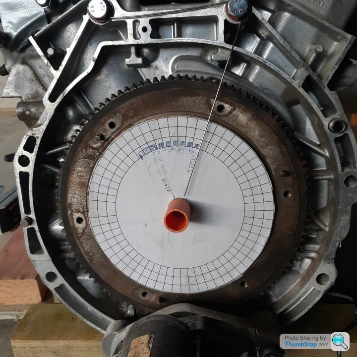
Thanks mate, I agree - this may seem a foolhardy plan but luckily I am quite the hardy fool.Printed out a 60-2 tooth chart and glued it to the civic flywheel using a precision whittled piece of PVC electrical conduit the same diameter as the pilot bearing and hammered it into place with a precision 4" x 2". While the glue was curing I rotated the engine to the 2 tooth gap position and then measured the crank sensor signal until it went low (from 3.3V when no tooth is present to 0v when it detects the leading edge of the first tooth) and aligned the printed pattern with the precision bent piece of welding filler wire. The ECU needs to be programmed with the precise angle of the first tooth after the gap is detected to the crank No1 TDC, i.e the falling edge of the CKP signal. To run sequential fuel injection the cam pattern has to be determined (tomorrows job!) so that the ECU can at any time during synchronised counting of the cam pulse train determine if it is coming up on TDC cylinder 1 or Cylinder 5 after the tooth gap (since firing order is 142536 - refer cam pulley on page 10 of this thread)
Crankshaft Pulse train with photo trying to account for parallax error on wire;
Edited by F1natic on Thursday 26th August 09:27
Day zero of the build - have spent the last couple of days clearing out the workshop and it is now ready for the build table to go in this afternoon. Second job was mounting a fire extinguisher on the wall.
First fixtures on the table will be front and rear temporary fabrications that position the suspension knees (sitting against the right wall) in 3D space so that the true geometry, alignment and bump steer can be confirmed - any modifications will then be transferred back into the master CAD model.
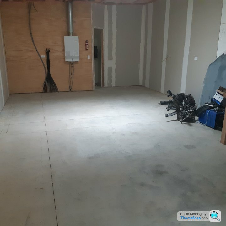
First fixtures on the table will be front and rear temporary fabrications that position the suspension knees (sitting against the right wall) in 3D space so that the true geometry, alignment and bump steer can be confirmed - any modifications will then be transferred back into the master CAD model.
Gassing Station | Readers' Cars | Top of Page | What's New | My Stuff