540HP NA 7L V12 3 seater
Discussion


My build table is a bit different as I do not have many flat frame members at floor level. The twin outer rails allow me to position the cross-rails at the working position with either g-clamps or tack welded tabs. Vertical position is achieved by threaded rods and angle iron tube supports to hold things in the exact positions required while I go back and forth from the drop saw to get fits just right. If building tube frames is your thing I recommend paying to watch the Tim McAmis chassis build video on his website, it gives some really good guidance and I got a lot of ideas from him. It's easy to take measures to the datum plane as it's on the underside of the cross rails. Since NZ is currently in full Covid lockdown I have not been able to tap an M16 thread into the foot plate for height adjusting - will be easy to add later. As a true miser I bought the leveling bolts in a hardware shop firesale about 6 years ago knowing I would need them eventually - they were 4 for a dollar. The steel for the frame is well and truly seasoned (i.e rusted to hell but I got it for a bottle of wine when a neighbour moved last year - thanks again Simon!)

To ensure that everything is built to the drawings I will shortly install the reference datum line running down the central axis and also another perpendicular at the center position. The datum line is high tensile steel wire known as locally as No. 8 wire. I get a bit of a kick out of using no.8 as it's a big part of NZ culture, as due to our isolated location a lot of early pioneers were very creative with it's end uses, I think it's fitting to use it here as I have a roll lying around!

To ensure that everything is built to the drawings I will shortly install the reference datum line running down the central axis and also another perpendicular at the center position. The datum line is high tensile steel wire known as locally as No. 8 wire. I get a bit of a kick out of using no.8 as it's a big part of NZ culture, as due to our isolated location a lot of early pioneers were very creative with it's end uses, I think it's fitting to use it here as I have a roll lying around!
Edited by F1natic on Sunday 29th August 09:56
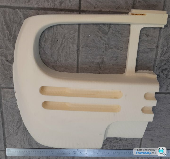
Under lockdown level 4 I have run out of steel to work on the frame, so have been plugging away on with the interior buck.
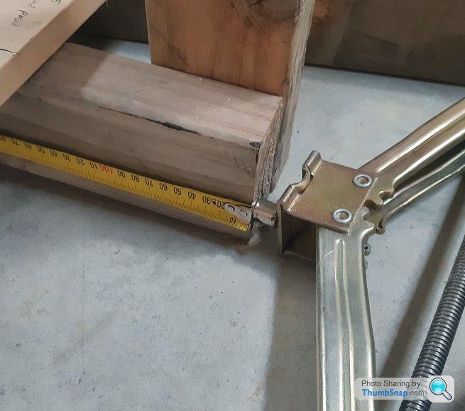
Turns out wood is not magnetic so my usual technique of holding the end of the tape measure to the metalwork can't be used until I started doing this, saves a lot of hassle.
The CAD model helps set the dimensions and my 3 favourite "working on your own" tools for turning MDF into a car interior are clamps, scissor jacks and ratchet tie downs. With these 3 tools you can very accurately position the sections while the glue sets.

The build table is a great flat surface for doing woodwork on, lots of clearance for the clamps.

With the aid of duct tape the position of the gearshift has been confirmed, moved it 12mm from where the CAD model was to get the right feel. The interior mouldings will be in separate pieces to allow fitting into the space frame, the drivers tub will be made first and transferred to the build table assembly ASAP so that the gearshift linkage can be proven out early in the build (essential to prove BEFORE the Tbox castings are made in case reality is different from CAD!)

Turns out wood is not magnetic so my usual technique of holding the end of the tape measure to the metalwork can't be used until I started doing this, saves a lot of hassle.
The CAD model helps set the dimensions and my 3 favourite "working on your own" tools for turning MDF into a car interior are clamps, scissor jacks and ratchet tie downs. With these 3 tools you can very accurately position the sections while the glue sets.
The build table is a great flat surface for doing woodwork on, lots of clearance for the clamps.
With the aid of duct tape the position of the gearshift has been confirmed, moved it 12mm from where the CAD model was to get the right feel. The interior mouldings will be in separate pieces to allow fitting into the space frame, the drivers tub will be made first and transferred to the build table assembly ASAP so that the gearshift linkage can be proven out early in the build (essential to prove BEFORE the Tbox castings are made in case reality is different from CAD!)
Clamped a couple of 30x30 box sections to the build table and tensioned the datum wire by backing the M16 cap head out of its nut. The wire runs through a hole drilled in the cap head screw so that the distance between the opposing wire crimps is increased until the right "twang" is reached. The magnetic tape measure sticks to it easily and there is no deflection even against a gentle pull, so will weld the uprights in place and use the wire as the datum for polar co-ordinates while building the frame. The crossbeams just touch the top of the line at the center position , so there is no measurable sag. The perpendicular transverse datum will be run just below the longitudinal datum. Will borrow a transit to check at all positions on the "table", but its looking useable to the calibrated eyeometer.

Edited by F1natic on Saturday 25th September 09:10
Won't be posting any of my welding for a while as this site has rules about offensive pictures. However to give morale a boost decided to pull forward a few years some bodywork trials - full scale rear plug underway. Going the route of CNC cut foam, covered with epoxy and glass to form a sandable shell for priming, then pull a female mould off the plug. Cardboard laminations proved too time consuming to assemble.
end goal;
https://www.infinitous.co.uk/ourshop/prod_7186558-...
end goal;
https://www.infinitous.co.uk/ourshop/prod_7186558-...
Edited by F1natic on Saturday 2nd October 04:28
F1natic said:
Under lockdown level 4 I have run out of steel to work on the frame, so have been plugging away on with the interior buck.
With the aid of duct tape the position of the gearshift has been confirmed, moved it 12mm from where the CAD model was to get the right feel. The interior mouldings will be in separate pieces to allow fitting into the space frame, the drivers tub will be made first and transferred to the build table assembly ASAP so that the gearshift linkage can be proven out early in the build (essential to prove BEFORE the Tbox castings are made in case reality is different from CAD!)
Reminds me of the BoraWith the aid of duct tape the position of the gearshift has been confirmed, moved it 12mm from where the CAD model was to get the right feel. The interior mouldings will be in separate pieces to allow fitting into the space frame, the drivers tub will be made first and transferred to the build table assembly ASAP so that the gearshift linkage can be proven out early in the build (essential to prove BEFORE the Tbox castings are made in case reality is different from CAD!)

AW111 said:
Reminds me of the Bora
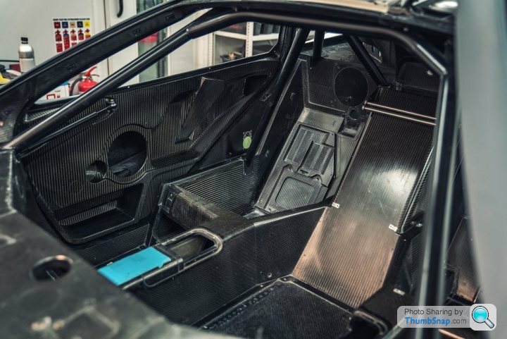
Nice shot, I think you are onto something, I find the Bora design quite appealing. Having never been inside one of these is that a storage compartment by the door? The drivers seat is arguably the most critical part to get right so will be roughing out an MDF tub to spray polyurethane foam into and take a butt print to get the seat form comfortable and snug. The chassis spars angle in behind the drivers seat so width decreases quickly so it needs to fit both the driver and the tub.
No Sound said:
An interesting project, I will keep my eye on this one to see how you get on with the built. Andy
Thanks Andy, got to say I am glad you are back onto your project too. Progress made - mucking around with the CNC router settings to try and improve cutting times, but learned the hard way that push too fast and the material balls up on the cutter and ruins a perfectly good part. Made a 1/10 scale part to test the 1/8" cutter settings.

Next priorities are;
test engine frame (welding and tube fitting practice)
finish the interior seating buck
get the suspension bump steer measured
Edited by F1natic on Saturday 9th October 04:32
Agreed, they do look very classy - however my leatherwork skills are not up to that level yet so will be simplifying the spec.
My favourite F1 interior is chassis 69, so the end goal is something like this;

Also the easiest way to save weight on a part is by not including it! The passenger seats are built into the composite tub, but they are different to the F1 design.
Their form is the same as the drivers seat (close to the Bora design) and have more shoulder width for the passengers. Running transverse engines has made things quite tight in this passenger shoulder area so the seating buck and prototype door fitment and operation are early in the build schedule in case reality requires adjustment of the master model. Door latch mechanisms are from a Mercedes SLK.
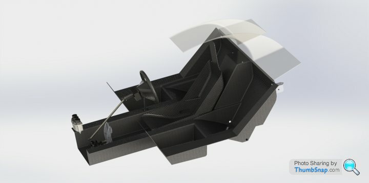
Drivers seat is a one-off fabrication that has to pass load testing with certifier, jury is still out on final design form but will be something close to the original. Have decided to drop the adjustment rails as the spaceframe crossbracing runs under the tub so the cabin actually sits a fraction higher. So my adjustment rails weigh zero kg! The pedal assembly and steering wheel positions are adjustable. There is a lot of space under the front of the drivers seat - as long as anything stowed under there cannot fly loose and jam a foot control I intend to utilise that space.

My favourite F1 interior is chassis 69, so the end goal is something like this;
Also the easiest way to save weight on a part is by not including it! The passenger seats are built into the composite tub, but they are different to the F1 design.
Their form is the same as the drivers seat (close to the Bora design) and have more shoulder width for the passengers. Running transverse engines has made things quite tight in this passenger shoulder area so the seating buck and prototype door fitment and operation are early in the build schedule in case reality requires adjustment of the master model. Door latch mechanisms are from a Mercedes SLK.
Drivers seat is a one-off fabrication that has to pass load testing with certifier, jury is still out on final design form but will be something close to the original. Have decided to drop the adjustment rails as the spaceframe crossbracing runs under the tub so the cabin actually sits a fraction higher. So my adjustment rails weigh zero kg! The pedal assembly and steering wheel positions are adjustable. There is a lot of space under the front of the drivers seat - as long as anything stowed under there cannot fly loose and jam a foot control I intend to utilise that space.
Edited by F1natic on Saturday 9th October 23:59
Gassing Station | Readers' Cars | Top of Page | What's New | My Stuff