540HP NA 7L V12 3 seater
Discussion


PAUL500 said:
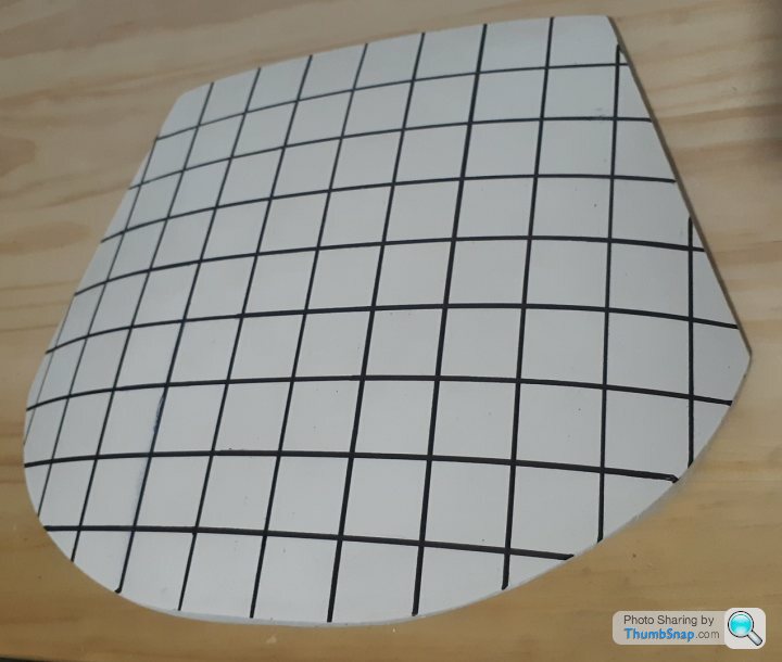
Front screen is the only thing left to sort, Pilkington here in the UK will make one offs from a mould or will cut down an existing screen if it has a similar shape, so still researching that area.
Impressive specification Paul, what do you think the torque limit for the 355 box is?I have actually pretty much given up on the idea of finding a suitable screen - the Artiplastzabrze attempt used the cutting and disguising with banding, but it looks a little "off" to my eye. Therefore have been conducting experiments in a small muffle furnace at 650C with stacked 1.75mm pieces of glass and they have formed to the contour of the stainless steel mould quite well. Have formed up to 6mm thick, but need to eliminate some small surface pock marks, currently using talc as the release agent so going to try boron nitride next. Once the pocking is resolved I will be moving to larger scale tests and then need to find someone with an autoclave to do the PVB lamination tests (145C at 10 bar).

Also have CNC cut a 1/10 scale female mould in polystyrene foam and cast a plaster of paris plug, the contours feel nice.
New Zealand, much like the rest of the world, has gone into lock down. Over the next 4 weeks, if I stay healthy, plan to bang out the interior detail. Fortunate that I can work from home and thus have brought a 3D printer home. The distraction from the outside world events will be welcome.
Good luck to everyone, it is a s
 tty hand we have been dealt, hope you can make the most of it.
Edited by F1natic on Tuesday 24th March 10:50
Indeed when Olas posted incorrectly on the 7th March in response to RoverP6B's comment back on 24th August I decided, given the brevity of their statement, that I would not draw any attention to it (although my pedantic nature put up a lot of protest!). I commend you Caddyshack for your attention to detail.
Edited by F1natic on Thursday 26th March 00:21
PAUL500 said:
We have a long term F40 LM version of what you are doing, based on a 355 chassis and running gear, but fitted with a 575 V12 engine.
Hi Paul, do you have any pics posted? (with a link perhaps?) I am always very interested in learning from others who have blazed a trail. Are you aware of the work that F40 Developments did here in NZ? They are one of my toolmakers and I have spent hours poking my nose into their car. The owner regularly attends the "Leadfoot festival" (which I hope to attend with my car when its done).
Edited by F1natic on Thursday 26th March 03:23
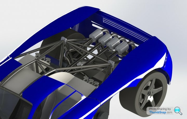
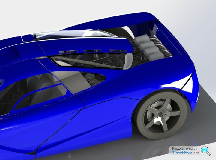
Nothing like bashing away at solidmodelling for a few hours only to find the catalytic converter clashes with the rear subframe. Two steps forward, one step back - still making progress though. Only one exhaust pipe is shown in the image of the "powerpack" assembly - the whole unit as shown will be unbolted for easy maintenance/inspection.
The rear panel is looking quite close.
First engine configuration will use the stock intake manifolds, but final goal is independant throttle bodies as shown, which will end up behind the passenger windows.

The rear panel is looking quite close.
First engine configuration will use the stock intake manifolds, but final goal is independant throttle bodies as shown, which will end up behind the passenger windows.

shalmaneser said:
Would be interested to see what it looks like!
I have spent years designing the internal gubbins of the Tbox, so am a little hesitant to show any detailed engineeering views, however I did a quick sketch of the concept that hopefully makes the "simple" mechanism clear. 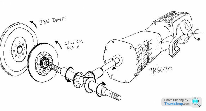
The standard dual mass flywheel and standard clutch feed the 344Nm of torque into each pinion (nearside clutch not shown for clarity), which drive their respective sides of the crownwheel. The crownwheel is connected to the input shaft of the corvette gearbox. The corvette box is designed to withstand the inertia of a long cardan shaft and its synchronisers are suitably robust. The inertia of the 2 pinions is of a similar level to the cardan shaft.
With both clutches engaged and the gearbox in a gear the engine torque path to the roadwheels is reacted on each respective side of the crownwheel. The engines do not drive each other or resonate with each other due to crank windup because the crownwheel and rolling resistance dampen the output. Even in neutral the oil drag losses of the gearbox should prevent destructive geartrain rattle. The tbox has it own separate lubrication system.
It is just like a tandem bicycle, the front riders' pedaling does not force the legs of the rear riders legs around as the rear wheel absorbs the pedal effort, but the pedalling effort can be doubled if the rear rider puts in some legpower!
If one engine was to have a fueling or spark issue then the malfunctioning motor will also get driven by the good engine, but with 2 healthy engines each running on independant and identical ECU's they should both contribute to driving torque equally.
Edited by F1natic on Friday 3rd April 08:20
threadlock said:
for pulling away I'd have thought any mis-match in the bite-point and the engaged engine would spin up wildly through the disconnected clutch before the second clutch engages. You'd get no drive to the wheels until both are engaged.
Sorry, but thats not how the mechanism works. Lets say we have selected 1st gear and both clutches are in, as the clutches are released you are right , inevitably one clutch will bite before the other, however the crownwheel between the pinions prevents "crosstalk" between the engines. One pinion cannot spin the other with out spinning the drive output, which is connected to the road wheels. There is no differential movement in this setup, plus I have built it in lego so I know it works!Edited by F1natic on Friday 3rd April 10:35
stevesingo said:
With the engines clutched independently, the engine note(s) will be invariably out of sync. I will sound interesting at times.
A friend was good enough to sample a honda V6 at full throttle and editted the audiotrack to give some overlap, it didn't sound wonderful like a V12 - more like a V6 with an echo. The sound of the powerplant has a massive influence on the driving experience (just watch Chris Harris driving an F50). However the sound of out of sych motors is not a prime consideration during early development testing - proving the reliability of the Tbox as soon as practical is my focus. Perhaps it may then be possible to synch the firing signal from one ecu and retard the other to match the 30 degree offset required during clutching events, however I don't believe this has ever been done so will probably just live with it "as is" and just get my enjoyment from the acceleration. stevesingo said:
In my mind I see that when pulling away from a stand still (if there is a mis-match in engagement), one clutch would start transferring drive to the pinion, which should start the car moving. If any throttle is applied, the second engine revs will rise until such a point where the clutch starts to transfer torque. This might be difficult to control.
You are utterly correct, and it is not a condition I had considered enough, thanks for your post. I was expecting to be dropping both clutches rapidly almost everywhere all the time.... Any throttle during moving off could cause a rev rise on the unloaded engine and could wear/glaze the clutch prematurely. I had to go out and drive around in my old manual car, checking the timing of the clutch release and bite point position. On the level the standard technique for a Mclaren F1 would be best (https://youtu.be/nk3DGaZ529E?t=117) as the engine torque even at idle is enough to get the car rolling. Using a pair of standard roadcar engines gives much greater flywheel effect compared to the f1, so would be an advantage in the "moving off without throttle" situation.
Aluminium flywheels on drysumped race engines are on my future upgrade list if the Tbox works, but using the stock dual mass flywheels will prolong the life of the Tbox gears enough for me to get some development miles on the chassis while I build the bodywork. If the Tbox turns out to be as tough as I expect then converting over to less damping for the sake of throttle response is part of the long term plan.
If the rev rise on unloaded engine is an issue during testing (and hill starts are when this issue would be obvious) I may have to put an extra idle adjustment feature into each ECU so if "zero road speed" and "clutch engaged" and "handbrake on" are detected the idle air valve opens to give a high idle (tunable from the drivers seat with a pot) so that the "loose " engine is prevented from revving up too much. It would almost act like an anti-stall. Once the clutch is fully released or road speed is above zero or the handbrake is off then high idle would be disabled. Trickling along in heavy stop start traffic is a good example of high clutch use and the tunable idle may be very useful for matching variable road conditions, although I must keep the system as simple as possible in the first iteration. It may seem counterintuitive but lightly applying the handbrake (enough to operate the switch but not the brake) could help the car move off smoothly in stop start. Interesting optionthat I had never considered, thanks!
Edited by F1natic on Saturday 4th April 09:13
Penguinracer said:
As a fellow Kiwi who's been based in the UK for almost 25 years - it always warms my heart to see guys back home in sheds taking on ambitious projects in economical ways.
Thanks mate! I recommend reading Patrick Harlows' book on NZ manufactured cars - you will be amazed at some of the projects that he uncovered - ISBN 978-1-877427-51-0 

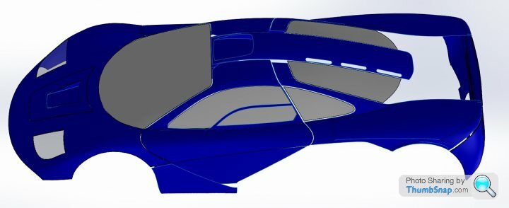
After looking long and hard at a range of photos I have settled on the roadcar nose - easy to modify afterwards for a racing version. The first iteration is a roadcar so that decided it for me. The shell (4mm thick) in polyester resin with proper thickness glazing is 116 kg as shown, but there is a lot of detail and therefore weight missing. Moving onto the interior now.
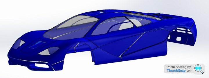
XP6 is born!
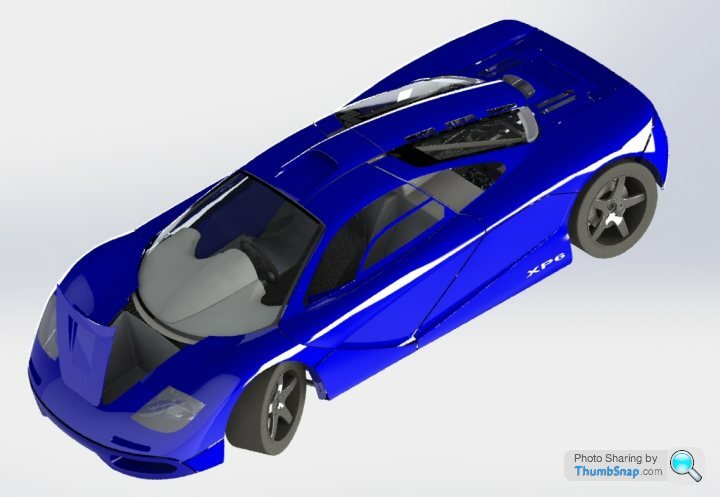
The frunk volume is 4 cubic feet (approx 112l) - enough for soft luggage. The brake and clutch reservoirs are accessible behind a panel on the firewall.
Still working on the Interior - I may be some time.....
Also working through the final checklist on legal requirements for road certification - hence things like the front indicators have now been modelled using Hella 2168 units. All the signal lighting will be modern LED type.

What a wormhole the LVVTA 175-00(03) seatbelt anchorage regulations can be. The seatbelt lug points will penetrate the interior panelling, shown as cutouts in the carbon fibre tub below, therefore attaching the seatbelts directly to the 4130 steel spaceframe. The rule is each lug has to be at the intersection point of a minimum of 2 tubes. Lots of iterations involved in getting those in place efficiently.
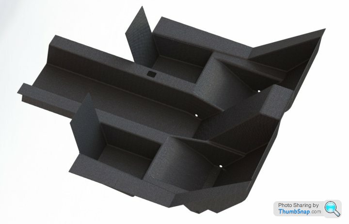
To make certification for the road as easy as possible I have followed the well troden path of a steel spaceframe with lightweight (i.e thin and non structural) carbon fibre diapraghm panels, such as the tub component. However these panels will boost the chassis stiffness, but they are mainly there as bling and to stop my legs poking out of the gaps in the frame.
Final fuel tank sizing will be 60L, good enough for a crusing range of 500km and maybe 100km of "enthusiastic" driving. There is space for an optional pair of auxilary long range tanks which could comfortably take capacity up to 90L. The certifier demanded a flanged design with lots of internal baffling and that the tank be retained by strapping, so best option is from 1.6mm thick aluminium sheet.
The Center of Mass only shifts a few mm with fuel load and passengers, going into the detail analysis has made me appreciate how clever the original design is.
Edited by F1natic on Monday 27th April 00:35
Gassing Station | Readers' Cars | Top of Page | What's New | My Stuff