540HP NA 7L V12 3 seater
Discussion


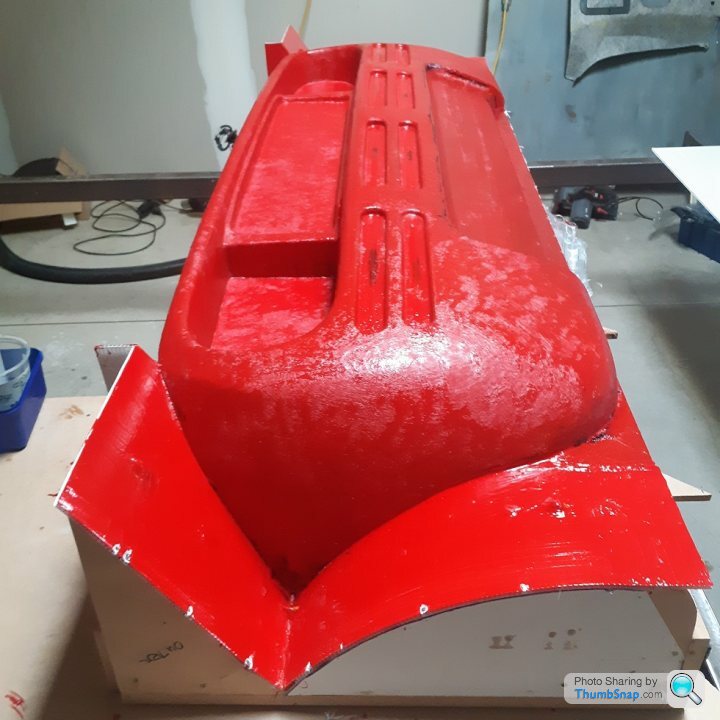
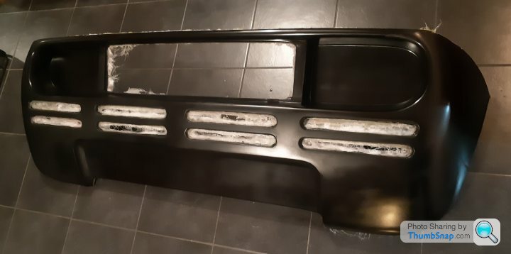
Gelcoat 1st layer looked a bit thin in a couple of spots (could see the primer underneath) so added second gelcoat in those spots.
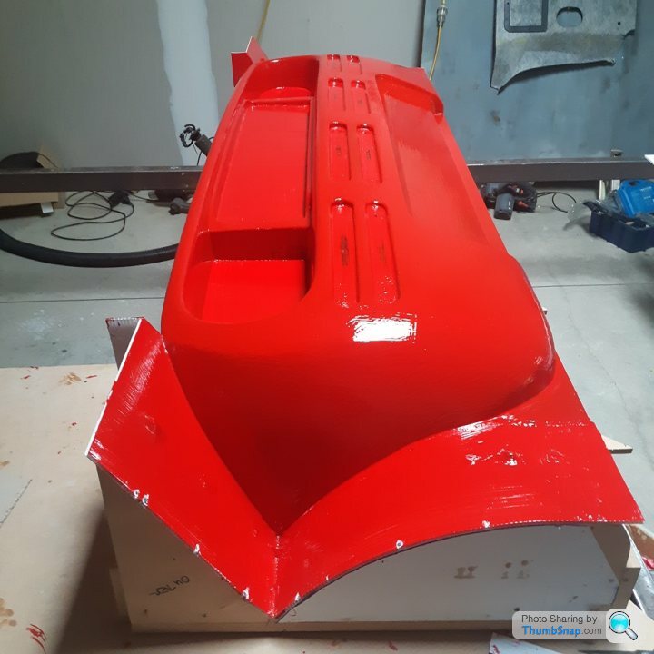
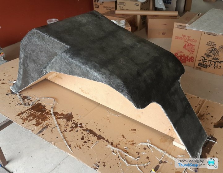
First layer is a fine tissue - with no trapped bubbles this time, even though it looks like it in this photo. Previous failure was mostly due to attempting too much at once - laminated the tissue and CSM at the same time. This time I am building up the first layers individually (i.e slowly and carefully until I get the hang of this caper).
First layer is a fine tissue - with no trapped bubbles this time, even though it looks like it in this photo. Previous failure was mostly due to attempting too much at once - laminated the tissue and CSM at the same time. This time I am building up the first layers individually (i.e slowly and carefully until I get the hang of this caper).
Edited by F1natic on Sunday 15th May 10:00
After what has literally been a month of Sundays' the rear mould exists. Unfortunately the plug stuck again very badly on the deep tail light recesses, everywhere else broke free nicely. Leaned on it with the biggest stick I could find and the styrofoam blocks making up the plug sheared away first so it is toast, but you can't make an omlette without breaking a few eggs, appears I am the same with plugs. The air injection worked really well for separating the mould away in the places where it hadn't chemically bonded. Internal surface is really nice so I am equally heartbroken and happy. Definitely going to be getting help during mould break in, do not want to go to level zero.
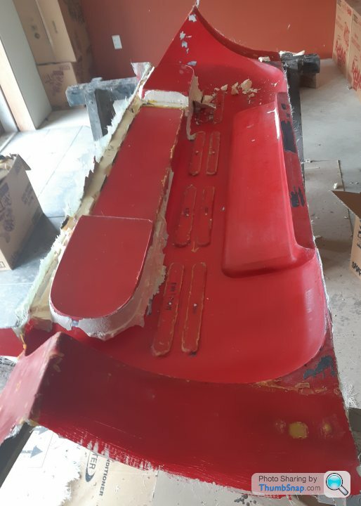
Luckily the mould is structurally fine, the gelcoat is quite thick in the troubled area so after a few very gentle scrapes to remove the adhered "plug sealer" the surface will polish up and be fine to use. I will be using PVA release for the parts, but will practice spraying it evenly on some test surfaces first.
That part is to big to be a one part mould I am afraid, those vertical surfaces where the gel coat has broken away is due to too much shear, you need to be splitting it so that the mould can come from them sideways rather than in shear, otherwise you will have similar problems removing the part from the finalised mould
The only other way would be to make a disposable buck then mould which you could cut apart and then prise off the part, but guessing you want to make more than one component from the mould.
The only other way would be to make a disposable buck then mould which you could cut apart and then prise off the part, but guessing you want to make more than one component from the mould.
Edited by PAUL.S. on Wednesday 8th June 14:29
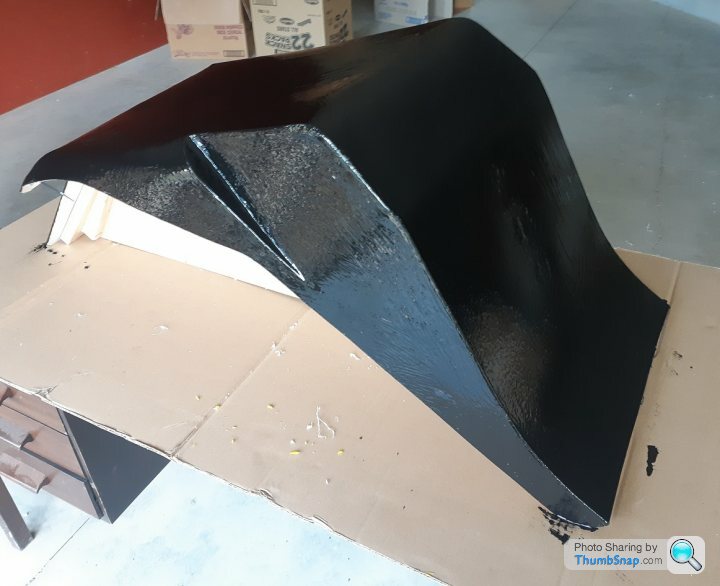
Progress has been mostly stalled for the last 6 weeks, fortunately air temperature and drying conditions were in range so managed to get some warmth into the mould by gentle sunbathing then 4 coats of wax and 3 coats of PVA release film sprayed on over the course of the day, finishing just as the sun was setting. Repaired the tooling gelcoat damage a few weeks ago, so next will apply a black gelcoat for the first layer of the rear panel. If the mold and part stick and breakaway in any areas this should make telling them apart when sanding through easy. I have made some mods and will be able to focus the shear force on the steep draft faces without overstressing the outer sections of the mould so am confident the part will be able to pull from the mould. Only one way to find out...
Edited by F1natic on Sunday 17th July 11:07
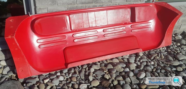
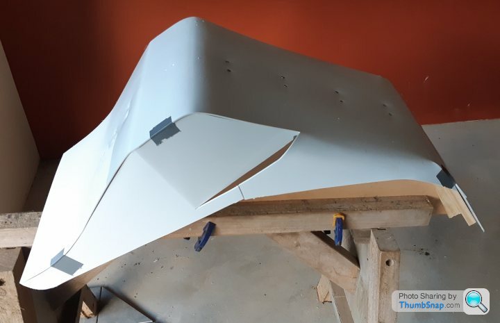
Milestone reached - rear panels pop off the tooling relatively easily when the proper PVA film is used. Very glad to have the goal (and experience) behind me and can now move on with the build.
Next milestone is the drivers seat in Carbon fibre, then the passenger seating buck mold (cabin), then the chassis proper.
Next milestone is the drivers seat in Carbon fibre, then the passenger seating buck mold (cabin), then the chassis proper.
As always following this with a mixture of awe and interest.
I do have a question:
To go from the rear panel, to the seats, to the chassis seems to me (a layman on such things) a bit of a scattergun approach. I’m sure this isn’t true though.
Do you have a project plan? Are you working through things in a certain order?
Keep up the good work though.
I do have a question:
To go from the rear panel, to the seats, to the chassis seems to me (a layman on such things) a bit of a scattergun approach. I’m sure this isn’t true though.
Do you have a project plan? Are you working through things in a certain order?
Keep up the good work though.
Thanks Rob,
I am using the old engineering technique of "Socks, then shoes." Cabin ergonomics and comfort are critical to the end experience, hence the upcoming focus on the driver and passenger seats. Once the cabin tub exists it will be placed on the build table and the frame built to the CAD model, however if any tubing needs repositioning it can be done without compromising the human interface. The fuel tank is highly dependant on the cabin being 100% complete as it must be a very tight fit to give maximum capacity. Once the cabin is frozen in place then major systems like font and rear suspension, steering and engine/trans package follow.
I did not expect the rear panel to take as long as it did, but all the techniques learned accelerate the next stages. I built the rear panel to see if the results I could achieve were going to look acceptable and reach a kill milestone as early as possible. It is such an iconic rear end and if it it was not "right to the eye" then not much point in proceeding with the rest of the bodywork - would have had to restyle as a cybertruck.
Edited by F1natic on Monday 25th July 01:08

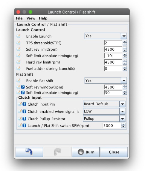
Back in April 2020 there was a discussion here about how the separate clutch bite points might cause a behaviour where the free engine could rev up under the "moving off" throttle setting, especially for a hill start. Learned the standard Speeduino launch control could be programmed in Tunerstudio to a low rpm setting to fake an "anti-stall", it only needs a clutch switch to feed a signal to the correct input pin. Will use the spare hall effect sensor to read the clutch position and an isolation switch on the control panel to turn the feature on or off on the fly - i.e. once the clutch pedal is pressed both engines will only rev to the set point regardless of throttle position, however once clutch pedal is released (or no voltage is supplied to the signal pin) normal throttle response continues. The first test drive will quickly establish if this feature is required, but will wire it into the ecu harnesses regardless.
Shown below is the wiki screen shot for the feature so would set launch rpm to something more like 2000 rpm.
Shown below is the wiki screen shot for the feature so would set launch rpm to something more like 2000 rpm.
Edited by F1natic on Sunday 14th August 08:58
The above solution is for a problem I don't actually have, any bumper to bumper city driving could easily be achieved with just one engine. Open road with twin engines will have fast shifts anyway.
The build has just had it's first anniversary...
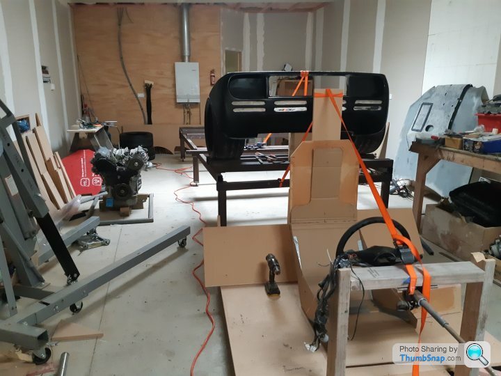
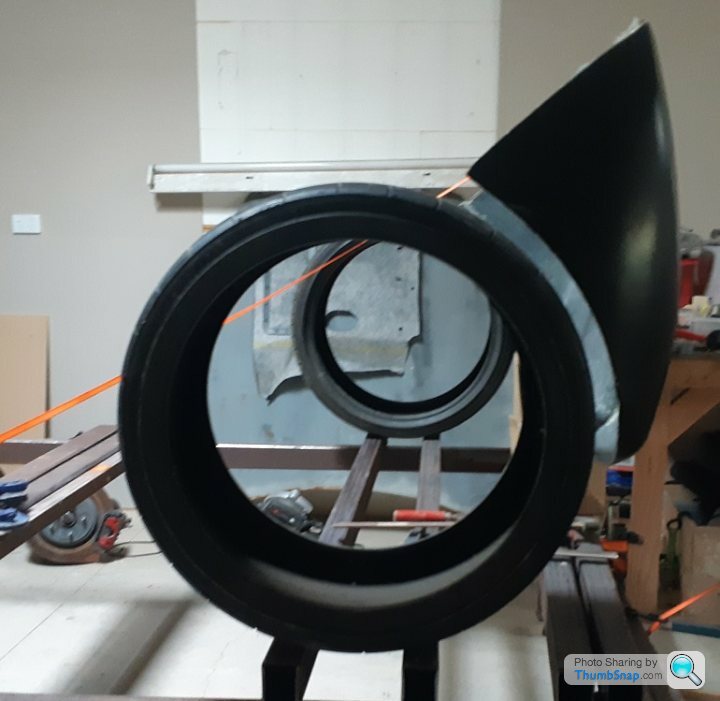
Happy with the tire to rear panel gap.
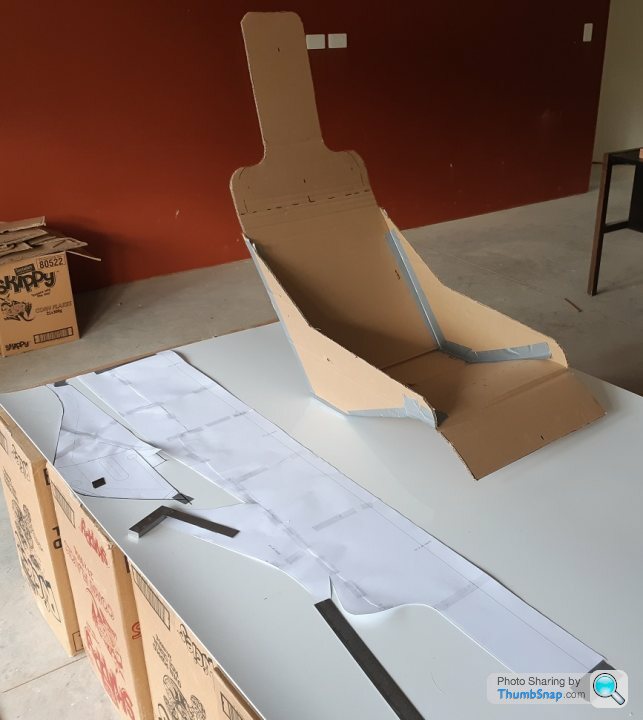
Working on the drivers seat currently, really happy with the feel of the cardboard mockup so committing to making a plug for it, however the plug will be adjustable if required. Cutting the template out from 1/8" polypropylene sheet and attaching to a wooden buck, if the seat that the tool produces is not right can easily adjust it and remake tooling. Means I can avoid the sanding malarky that the rear panel encountered = faster results!

The build has just had it's first anniversary...
Happy with the tire to rear panel gap.
Working on the drivers seat currently, really happy with the feel of the cardboard mockup so committing to making a plug for it, however the plug will be adjustable if required. Cutting the template out from 1/8" polypropylene sheet and attaching to a wooden buck, if the seat that the tool produces is not right can easily adjust it and remake tooling. Means I can avoid the sanding malarky that the rear panel encountered = faster results!
Thanks for the encouragement chaps.
With a little help from a 2kw heat gun was able to coax the polypropylene sheet to fold where needed and retain on a MDF profile template. Will put filleting wax over the screw heads to give a flush surface before applying the tooling gelcoat, fibreglass and polyester resin. Once the rough seat tooling is made from this plug a polyester/glass seat shell will be made and shaped foam blocks added do the internal cavity to give a snug comfortable fit. Plan is for a smooth CNC cut plug for the final road going version to produce an epoxy/carbon fibre tool & part for certification load testing.
The plug fits nicely into place in the seating buck.
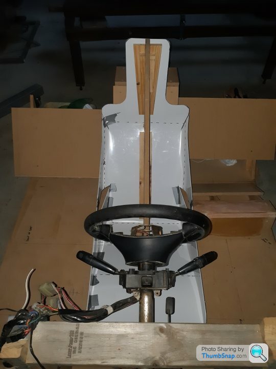
The curved sides are important for seatback stiffness but more importantly a space for passengers arms, while the cutout at the bottom of the seat matches the inwards angle of the structural spars either side of the driver, which allows for more space for passenger hips.

With a little help from a 2kw heat gun was able to coax the polypropylene sheet to fold where needed and retain on a MDF profile template. Will put filleting wax over the screw heads to give a flush surface before applying the tooling gelcoat, fibreglass and polyester resin. Once the rough seat tooling is made from this plug a polyester/glass seat shell will be made and shaped foam blocks added do the internal cavity to give a snug comfortable fit. Plan is for a smooth CNC cut plug for the final road going version to produce an epoxy/carbon fibre tool & part for certification load testing.
The plug fits nicely into place in the seating buck.
The curved sides are important for seatback stiffness but more importantly a space for passengers arms, while the cutout at the bottom of the seat matches the inwards angle of the structural spars either side of the driver, which allows for more space for passenger hips.
Edited by F1natic on Monday 26th September 03:51
Goal here is a fast and low cost seat tool that will produce a seat shell to verify driver movement and comfort in the cabin mockup. At this stage and for early test drives an ugly fibreglass unit is sufficient.
Sealed up all the screw heads and gaps with filleting wax
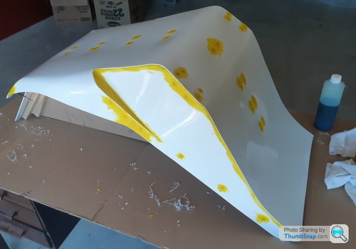
Gelcoat
Cheesey state of first stage of laminating resin is very easy to trim to the shape of the seat pattern.
Sealed up all the screw heads and gaps with filleting wax
Gelcoat
Cheesey state of first stage of laminating resin is very easy to trim to the shape of the seat pattern.
Edited by F1natic on Monday 26th September 03:48
Gassing Station | Readers' Cars | Top of Page | What's New | My Stuff