540HP NA 7L V12 3 seater
Discussion


While waiting for paint to dry progressed the front left upper wishbone and coilover mount, will cast this and check the result before making the RH side. Will be simple to change the caster and camber angles by unbolting this unit and replacing with one with the wishbone mounts in a different position, intention is to not have to modify the spaceframe while tuning the handling. 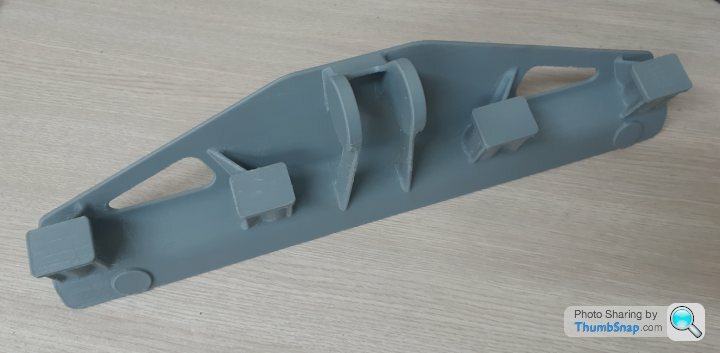

This is amazing F1natic - do you have any other build threads / blog / FB page we can follow along with?
I am in NZ too - wondering how hard cast aluminium components are to meet LVVTA standards? Do they make you jump through hoops?
Nice casting patterns. I recognise that filament...
I am in NZ too - wondering how hard cast aluminium components are to meet LVVTA standards? Do they make you jump through hoops?
Nice casting patterns. I recognise that filament...
Thanks Voldo, no I don't have anything on social media, almost every update is done here. The ECU related stuff is on the Speeduino thread under the same title as nobody has published details on getting the Honda J35 engine running on that platform yet, so sharing the learnings where I find them. Really want to get both engines to synchronise for a nice V12 sound however that can only happen when the ECU is open source variety, hence the choice of Speeduino.
We don't run aluminium often as sandcasting tends to be a more cost effective method for castings. No issues raised by LVVTA about the casting I am using, but would expect it is very much on a case by case basis.
Filament is the "cast grey" that I worked with Ben at Imagin plastics to develop for lost PLA use, we get really good results from it.
Edited by F1natic on Wednesday 1st February 07:03
You can check out my work at www.Whitleytune.com. All the castings on there are lost PLA with plaster moulds, I have just set up ceramic shell so looking forward going to the next level. Plaster is a pain but learnt a lot with it!

Will do Dom.
Waxed the plug multiple times, added fillets to all corners and sprayed all over with PVA release film.
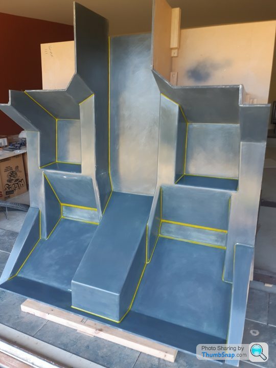
Had to work very quick to get this all spread before it gelled, one area had slump which thickened and went off quicker than desired. A small amount of sanding in the trouble spot tomorrow and another coat of gelcoat should smooth the surfaces out enough to progress to layup.

Waxed the plug multiple times, added fillets to all corners and sprayed all over with PVA release film.
Had to work very quick to get this all spread before it gelled, one area had slump which thickened and went off quicker than desired. A small amount of sanding in the trouble spot tomorrow and another coat of gelcoat should smooth the surfaces out enough to progress to layup.
Edited by F1natic on Wednesday 1st February 07:06
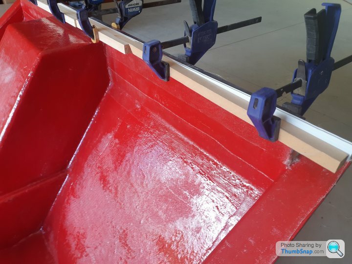
Tissue and a couple of layers of 200g/m2 bidirectional glass cloth have been applied to the plug but some major lessons learned on getting faster at layup. Made one big blunder and took too long with one section, resin started to get cheesy on the other side and I had to pull it off and chuck in the bin before it set on the plug. Good thing is the resin mostly went with the cloth so cleanup the next day was simple.
Have really struggled with getting tight corners to conform if the cloth is long, basically playing whack-a-mole with bridged cloth, stipple it into one corner and the tension pulls out the corner done previously. Now using 3" wide tape to reinforce the corners and cloth panels between the tape, very easy to work the cloth into position and the bubbles and kinks out. Top flange edge is a little shorter than it should have been so clamping coreflute strips on while curing to keep a nice sharp flat edge, otherwise the cloth seems to want to curl off and cannot be moved once set. A few layers of chopped strand mat to go then the big moment.
Have really struggled with getting tight corners to conform if the cloth is long, basically playing whack-a-mole with bridged cloth, stipple it into one corner and the tension pulls out the corner done previously. Now using 3" wide tape to reinforce the corners and cloth panels between the tape, very easy to work the cloth into position and the bubbles and kinks out. Top flange edge is a little shorter than it should have been so clamping coreflute strips on while curing to keep a nice sharp flat edge, otherwise the cloth seems to want to curl off and cannot be moved once set. A few layers of chopped strand mat to go then the big moment.
dom9 said:
Would be very interested in the process for the 3D print -> cast part, when the time comes... lots of pics please!
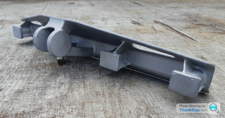
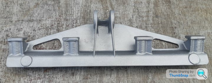
Dom, Since you asked here are the results of the first trial part. Main thing is to have a good 3D print as every surface blemish is replicated by investment casting. Essential rule is to feed the metal from thick to thin so that the part does not short fill or have internal shrinkage. Final prep of the cast metal surface is easy but time consuming and it can be faster to sand the pattern instead, however in this case I decided not to pour hours into cleaning up the pattern in case it did not succeed. I am quite chuffed with this result. Now to print the other side.
With the CAD model from last July as context;
Bulkhead mould update - removable panels came off easily and the mould is nearly finished, the 450g CSM is VERY resin thirsty and I ran out part way through. Now have enough to finish the job and bust it off the plug in a few days all going well.
Edited by F1natic on Wednesday 1st February 05:51

Thank you! Much appreciated! Looks fantastic!!!
So, if we go back a step for my tiny brain... You have printed the part and then how did you go from that to the mould?
Is it a sort of lost print technique and the printed part is covered in what almost looks like plaster there?
I'm fascinated by this as I don't have much need for a 3D printer but 3D print to casting i.e. make your own metal parts... now that interests me!
Seen some guys do it in a sand box on Youtube but the ones I have seen don't appear to be nearly as complex!
Agreed if the OP has the facilities there needs to be some stress analysis on that part. I can see the suspension forces are transferred into the tubular member above the shock mount but the casting doesn't look substantial enough and the bosses for the wishbone mounting don't look great.
Aluminium castings like this for non-structural parts are great but for critical suspension components spaceframe is much better I think.
Aluminium castings like this for non-structural parts are great but for critical suspension components spaceframe is much better I think.
threadlock said:
normalbloke said:
I’m struggling to see how that cast part can be even remotely strong enough. What am I missing?
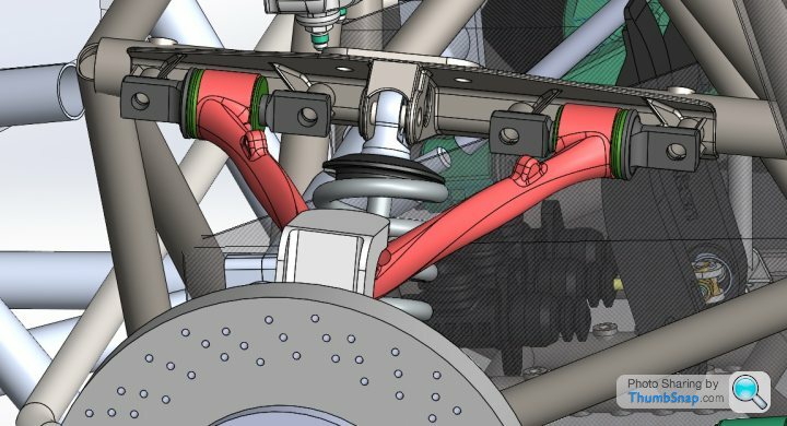
I felt the same when I saw it (as a BEng qualified mechanical engineer), but I assume OP knows what he's doing :-)There's a vertical load from the top of the springs. That looks like it is being carried directly into a bracket on the spaceframe:
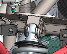
Hard to tell from this angle, but it may be that the load is being carried properly. And this is what the OP wrote about it last year:
F1natic said:
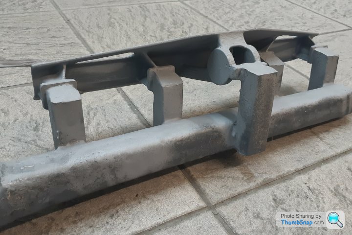
Back on page 6 of this thread I roughed out the UCA mounting plate, but have now developed the idea a bit further. The UCA mount plate is a bolt on part that allows quick and easy swap out to allow experimentation on the test mule settings for caster, camber and antidive angles on the front suspension. The shock loads transfer directly into a backing plate that is welded to the chassis tubing. The mount plate also stiffens the control arm chassis tube by acting like a huge gusset. It is also another part that has been designed to be 3D printed and cast. The outer most end bolts go through crush tubes welded into the chassis tubing, the tops of which can just been seen.
There will be lateral loads caused by cornering (in an impact, it would be best if the casting failed rather than destroying the spaceframe). But those won't be all that high, and are relatively easy to quantify.There will also be fore-aft loads from braking (assuming this is the front end, no acceleration-related loads). But I don't recall seeing the full CAD model of this area - it may be they're carried by lower links that are mounted in a different way, meaning the loads on this piece will be caused by a turning moment relative to the contact patch. Since the wheel diameter is quite large, so is the moment arm, meaning those loads are probably manageable.
I think this part stands a good chance of being OK; and, if note, it could easily be replaced by a fabricated part later.
Thank you all for the input, appreciate other eyes on the design. Thanks Skwdenyer for posting the close up and notes, the casting is bolted to the chassis tubes in 4 positions (at the ends near nodes with multiple tubes and 2 at the "shock tower"). The shock loads go directly into the chassis plate and backing tube so the casting is almost continuously a "spacer" under compression. The outer dogbone towers carry the majority of the upperwishbone loads to the casting mounting bolts at either end (The 2 bosses are visible in the underside photo). The towers locate the dogbones and are on a plate that has flanges both sides so that overall flex is decreased.
Perhaps I should have stated the part was cast in carbon steel BS 3100 A4, 320Mpa minimum yield, which has good strength and ductility. For the purposes of entertainment (the whole point of this build log) and review I will explain the loads and review a couple of good examples from recent high end sports cars later, however right now my focus this Waitangi long weekend is getting the interior bulkhead mould finished and off the plug.
Perhaps I should have stated the part was cast in carbon steel BS 3100 A4, 320Mpa minimum yield, which has good strength and ductility. For the purposes of entertainment (the whole point of this build log) and review I will explain the loads and review a couple of good examples from recent high end sports cars later, however right now my focus this Waitangi long weekend is getting the interior bulkhead mould finished and off the plug.
Edited by F1natic on Friday 3rd February 20:11
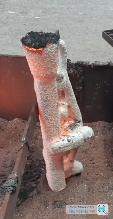
Dom, yes it's the "lost PLA" method. Same overall process as lost wax (https://www.investmentcasting.org/what-is-investment-casting.html) however the hollow PLA print is sealed and then used inplace of a wax pattern. You have to print the pattern at a slightly larger scale to cover the metal shrinkage rate for the part (which is geometry and metal dependant). The pattern is then glued to the standard wax tree using a sticky wax. Once the ceramic shell is formed it is then fired at 1000C which completely burns out the PLA if it has a low ash content. If the feeder system is good then you stand a good chance of getting a result, however it can be an iterative process. Being able to tweak the pattern at each iteration helps hone in on the best casting.
Gassing Station | Readers' Cars | Top of Page | What's New | My Stuff