540HP NA 7L V12 3 seater
Discussion


Robert, it's a naturally aspirated engine running on 91 grade fuel with stock 10.5:1 cr and factory ecu settings, and those numbers where recorded with multiple runs using 100% throttle command. Unfortunately I cannot see the throttle readings when it's set to record and therefore to get the curve I used WOT. Do you know a clever way to record the factory ECU outputs and build the full curve? My scanner is very basic. I am going to be using alpha-n strategy in Tunerstudio for the test engine, hence once I know what the factory timing table looks like i will only be left with the fuel table to sort. of course all this is when warmed up, cold start enrichment factors will have to be worked out too. One step at a time!
I am fairly sure this is the total advance since the service manual states 10 btdc at idle, scanner say 7 if at rolling idle, and fluctuating around 10 when stationary. While driving on light partial throttle the advance is around 30, will check with a timing light while the scanner is connected to ensure correlation before I carry any assumptions forward to the test engine. Thanks for prompting me to think about that!
I am fairly sure this is the total advance since the service manual states 10 btdc at idle, scanner say 7 if at rolling idle, and fluctuating around 10 when stationary. While driving on light partial throttle the advance is around 30, will check with a timing light while the scanner is connected to ensure correlation before I carry any assumptions forward to the test engine. Thanks for prompting me to think about that!
Edited by F1natic on Wednesday 23 September 19:30
Day job has sucked up all project time hence the lack of updates - no significant progress worth sharing.
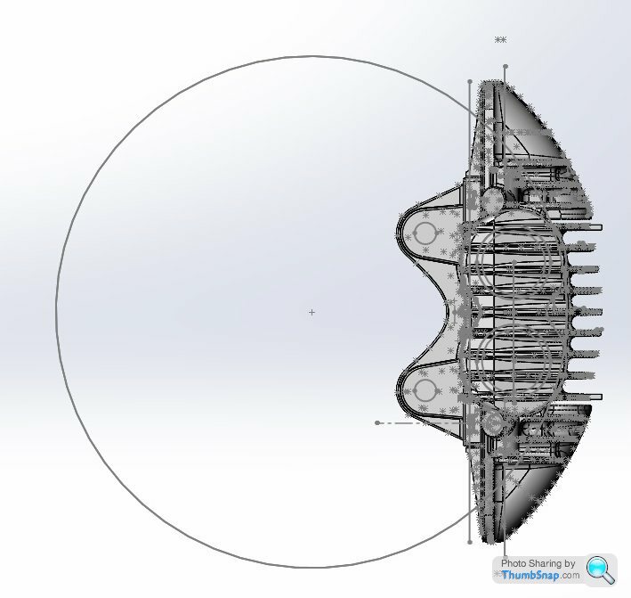
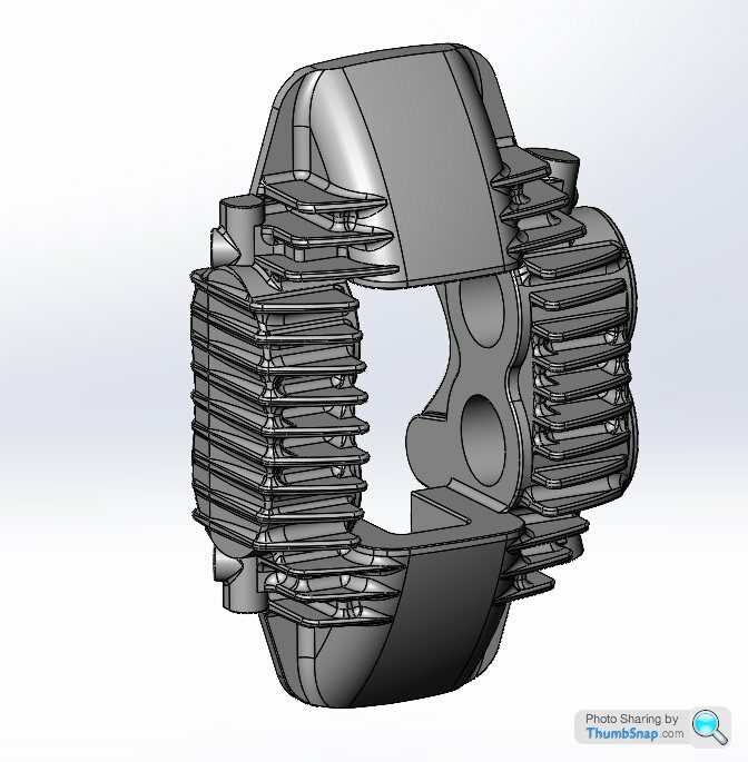
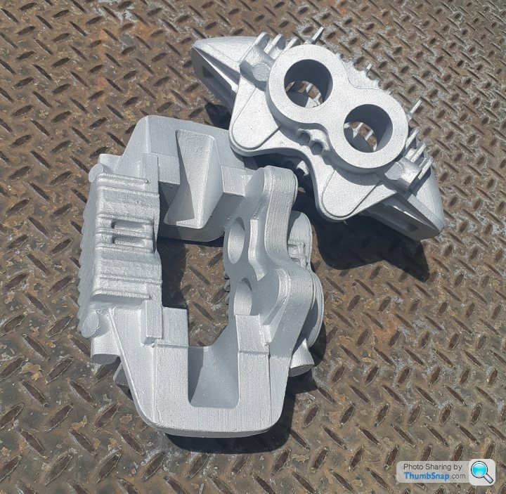
However just completed this job for a client, replicated a Zakspeed style brake caliper. Scanned dimensions using a CMM, then modelled the part in Solidworks to fit the point cloud, 3D printed some patterns and investment cast the result. Luckily the client is patient.
Original part;
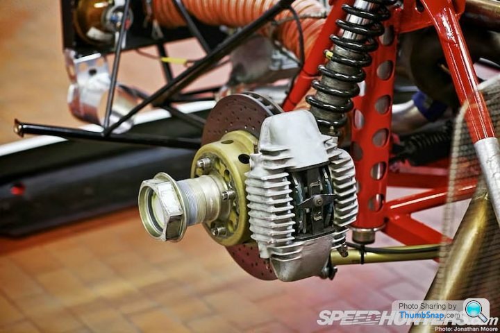
Details here; http://www.speedhunters.com/2013/02/fire-breathing...
Replicated part;
Expecting to release thread related updates later this month once works' silly season is over.
However just completed this job for a client, replicated a Zakspeed style brake caliper. Scanned dimensions using a CMM, then modelled the part in Solidworks to fit the point cloud, 3D printed some patterns and investment cast the result. Luckily the client is patient.
Original part;
Details here; http://www.speedhunters.com/2013/02/fire-breathing...
Replicated part;
Expecting to release thread related updates later this month once works' silly season is over.
Edited by F1natic on Tuesday 8th December 22:17
F1natic said:
Day job has sucked up all project time hence the lack of updates - no significant progress worth sharing.
However just completed this job for a client, replicated a Zakspeed style brake caliper. Scanned dimensions using a CMM, then modelled the part in Solidworks to fit the point cloud, 3D printed some patterns and investment cast the result. Luckily the client is patient.
Original part;
Details here; http://www.speedhunters.com/2013/02/fire-breathing...
Replicated part;
Expecting to release thread related updates later this month once works' silly season is over.
Nice one! I've recently learned that 3d-printing road-going brake calipers is already possible using SLM - might be interesting for anyone who does small quantities https://conti-engineering.com/highlights/additive-...However just completed this job for a client, replicated a Zakspeed style brake caliper. Scanned dimensions using a CMM, then modelled the part in Solidworks to fit the point cloud, 3D printed some patterns and investment cast the result. Luckily the client is patient.
Original part;
Details here; http://www.speedhunters.com/2013/02/fire-breathing...
Replicated part;
Expecting to release thread related updates later this month once works' silly season is over.
Edited by F1natic on Tuesday 8th December 22:17
TekoTime said:
Aha! Finally, something this idiot can give his expert advice on:
Plastic is not a good material for brake calipers. I'd recommend metal, or something.

Agreed, the pedal would feel quite mushy! Plastic is not a good material for brake calipers. I'd recommend metal, or something.
Edited by TekoTime on Thursday 10th December 21:47
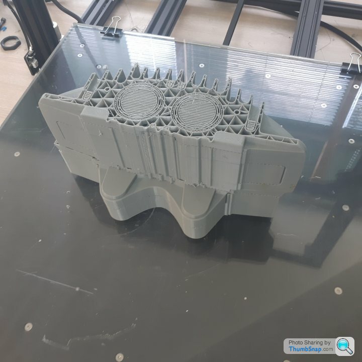
Just to clarify these parts were cast in aluminium, as per the genuine articles shown. However rather than sand casting from a cope and drag pattern box we use lost PLA, similar to lost wax casting or investment casting (worth a google). The patterns for these castings were 3D printed and then coated in a ceramic slurry and dried to form a mould. The patterns burn out completely when the ceramic mould is fired. We then poured the molten aluminium into the ceramic mould that has the perfect negative cavity shaped like the 3D print.
It's how I intend to make a lot of my more complex parts for my project, practice is always helpful.
Bodo said:
Nice one! I've recently learned that 3d-printing road-going brake calipers is already possible using SLM - might be interesting for anyone who does small quantities https://conti-engineering.com/highlights/additive-...
A laser sintering metal powder printer would be a great tool to have access too, however they are not common here in NZ. Great for making titanium parts, Rodin cars in the South Island are leading the way - but that option is not possible with my projects' budget. Edited by F1natic on Friday 11th December 02:15
YouTube research has uncovered an interesting implementation of twin radial engines (325 HP each), the Kamov KA 26 dates from 1969-1985. The engine crank output is turned 90 degrees by a bevel gear set to an output flange that incorporates rubber isolators, which then drive the input shafts of the main gearbox. Has to be the ugliest helicopter in the world, but has logged 1000's of hours, and it appears many are still flying in Hungary.
This one probably won't fly again but all the gubbins are there to see;
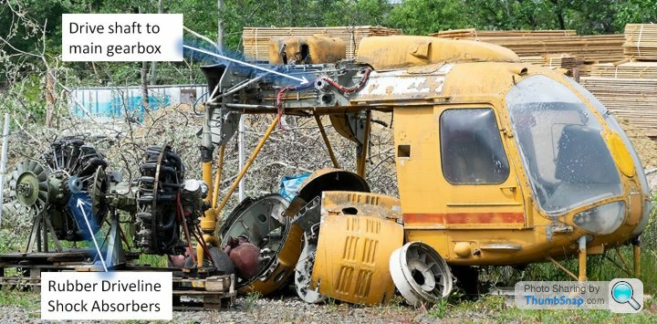
Startup is hilarious as being a radial engine the oil seeps into the lower cylinder when stationary. Firing up procedure is typically rotating by wrench until the cylinder is purged, then run up with compressed air until ignition is sustainable. Its amazing the spark plugs can clear the intense fouling...
https://www.youtube.com/watch?v=myyDoekcf50&t=...
This one probably won't fly again but all the gubbins are there to see;
Startup is hilarious as being a radial engine the oil seeps into the lower cylinder when stationary. Firing up procedure is typically rotating by wrench until the cylinder is purged, then run up with compressed air until ignition is sustainable. Its amazing the spark plugs can clear the intense fouling...
https://www.youtube.com/watch?v=myyDoekcf50&t=...
Edited by F1natic on Monday 14th December 09:03
F1natic said:
YouTube research has uncovered an interesting implementation of twin radial engines (325 HP each), the Kamov KA 26 dates from 1969-1985. The engine crank output is turned 90 degrees by a bevel gear set to an output flange that incorporates rubber isolators, which then drive the input shafts of the main gearbox. Has to be the ugliest helicopter in the world, but has logged 1000's of hours, and it appears many are still flying in Hungary.
This one probably won't fly again but all the gubbins are there to see;
Startup is hilarious as being a radial engine the oil seeps into the lower cylinder when stationary. Firing up procedure is typically rotating by wrench until the cylinder is purged, then run up with compressed air until ignition is sustainable. Its amazing the spark plugs can clear the intense fouling...
https://www.youtube.com/watch?v=myyDoekcf50&t=...
What an awesome bit of iron-curtain engineering! looks great...although that guy on the left was making me worried, so damn close to the rotors!This one probably won't fly again but all the gubbins are there to see;
Startup is hilarious as being a radial engine the oil seeps into the lower cylinder when stationary. Firing up procedure is typically rotating by wrench until the cylinder is purged, then run up with compressed air until ignition is sustainable. Its amazing the spark plugs can clear the intense fouling...
https://www.youtube.com/watch?v=myyDoekcf50&t=...
Edited by F1natic on Monday 14th December 09:03
Hi I've just stumbled on your thread. Love it, great outside the box thinking. I love the T box, brilliant, and being where it is it only sees engine torque, perfect. I can't see you having any issue with uneven drive when releasing the clutch at all, it will all just sort itself out.
I've got a Mazda KL powered open wheel racing car here in South Australia (twin turbo dry sump, F1 gearbox) That I'm working on repowering with a Cosworth DFX Indycar engine.
I'm looking forward to seeing your progress.
I've got a Mazda KL powered open wheel racing car here in South Australia (twin turbo dry sump, F1 gearbox) That I'm working on repowering with a Cosworth DFX Indycar engine.
I'm looking forward to seeing your progress.
roy928tt said:
I've got a Mazda KL powered open wheel racing car here in South Australia (twin turbo dry sump, F1 gearbox) That I'm working on repowering with a Cosworth DFX Indycar engine.
Thanks for your comments Roy, much appreciated. Do you have any pictures you could post of your setup? I am always keen to see how other people integrate their powertrains into their projects, especially when matching components that were never intended to go together! Over the summer break I will be completing the detail design of the bell housings and pumpkin for the T box and casting them all early next year, so any and all advice gratefully accepted. Clutch actuation and how to make it as low a profile as possible is my current learning curve. There is enough width in the engine bay of my car, but I would still like to make it as compact as possible.
Bellhousing will be CC601 Aluminium, T-box pumpkin will be SAE 4130. The pumpkin will be like a diff head, using thin walls that are still very stiff to resist the deflection of the pinions while giving big spigots to align the bellhousings. Might be a bit heavier than required but the goal is for it to last my lifetime.
Edited by F1natic on Friday 18th December 01:03
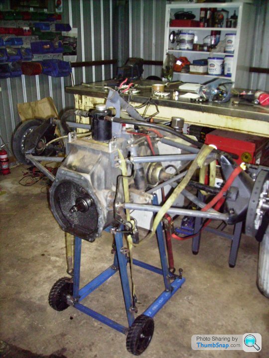
Nothing much to see here, the transaxle is from a Euro Brun ER 188 a simple adaptor plate to the Mazda KL a conventional 7 1/4 " twin plate clutch. No flywheel or ring gear, the engine is started by plugging an external starter into the back of the box and starting it through the input shaft, no fun if you stall it away from the pits......
The transaxle bellhousing bolt pattern is Cosworth DF V8, so the DFX will bolt straight up to it. Probably the first time in the whole car where 2 pieces simply bolt together!
Great setup Roy, it must be exhilarating to drive. The rear fabricated uprights are superb, I also like the high flow drainage on the radiator. The more I look at the photos the more questions I have!
Any lessons from setting up the dry sump? Brand of pump chosen or reasons? Did you have to modify the existing sump or fabricate a new version? I would really like to get my stage 2 test mule running with dry sumps, which will only happen once I have run around 1000 km through the tbox with the stage 1 stock wet sumps.
Any lessons from setting up the dry sump? Brand of pump chosen or reasons? Did you have to modify the existing sump or fabricate a new version? I would really like to get my stage 2 test mule running with dry sumps, which will only happen once I have run around 1000 km through the tbox with the stage 1 stock wet sumps.
Love the smell of MDF in the morning...
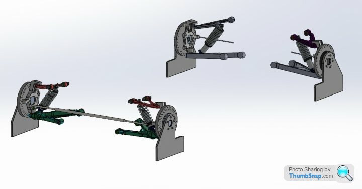
Cutting out some dummy wheels - they will place the C6 spindles at the correct ride height and allow for easy assessment of camber and toe changes through out suspension movement to confirm that the positions of the inner wishbone brackets as modelled in CAD also work in reality.

Cutting out some dummy wheels - they will place the C6 spindles at the correct ride height and allow for easy assessment of camber and toe changes through out suspension movement to confirm that the positions of the inner wishbone brackets as modelled in CAD also work in reality.
This is how I intend for the dummy wheels work, they are the same width at the base as the rim diameter so can be used to gauge toe against factory settings. I want to mock up the suspension pickups before committing the final bracket positions into the design approval document, since that is the document my certifier will judge my final build results against.
Cutout is for brake caliper clearance. The baseline is offset from the "perfect" tire outside diameter to account for the vertical deflection of the contact patch due to the relevant corner load (estimated at this stage since I don't have the final wheel tire combo to load test).
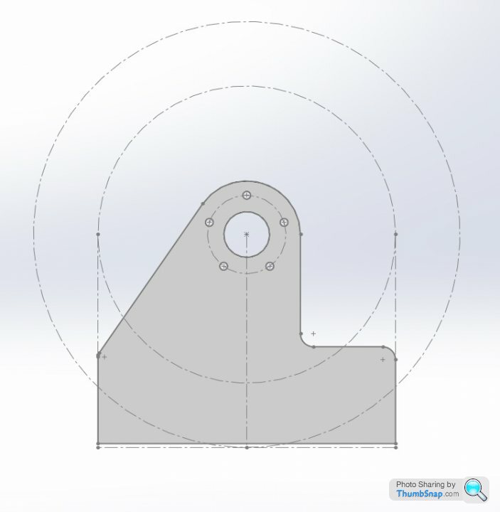
Cutout is for brake caliper clearance. The baseline is offset from the "perfect" tire outside diameter to account for the vertical deflection of the contact patch due to the relevant corner load (estimated at this stage since I don't have the final wheel tire combo to load test).
F1natic said:
Bodo said:
Nice one! I've recently learned that 3d-printing road-going brake calipers is already possible using SLM - might be interesting for anyone who does small quantities https://conti-engineering.com/highlights/additive-...
A laser sintering metal powder printer would be a great tool to have access too, however they are not common here in NZ. Great for making titanium parts, Rodin cars in the South Island are leading the way - but that option is not possible with my projects' budget. 
Totally agree Bodo, fingers crossed.
Spent a few hours prepping the test motor for its imminent first fire-up. Had to understand and measure the crankshaft position sensor (CKP) signal and how the signal is produced on the 60-2 wheel, especially the angular offset between the first tooth after the gap and TDC of no.1 cylinder.
12V or 14V feed makes no difference to the output signal;
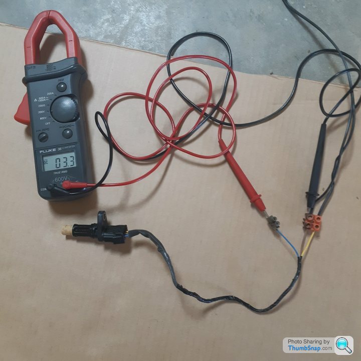
This is the 2 tooth gap that the ECU detects
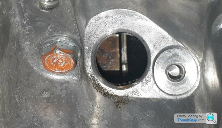
Once the first tooth after the gap is sensed by the hall sensor the signal drops from 3.3V to zero, the falling edge at this angle is used to synchronise the ECU so that the firing of the ignition coils (Coil on Plug type using 5V signal) and injectors matches the true mechanical positions.

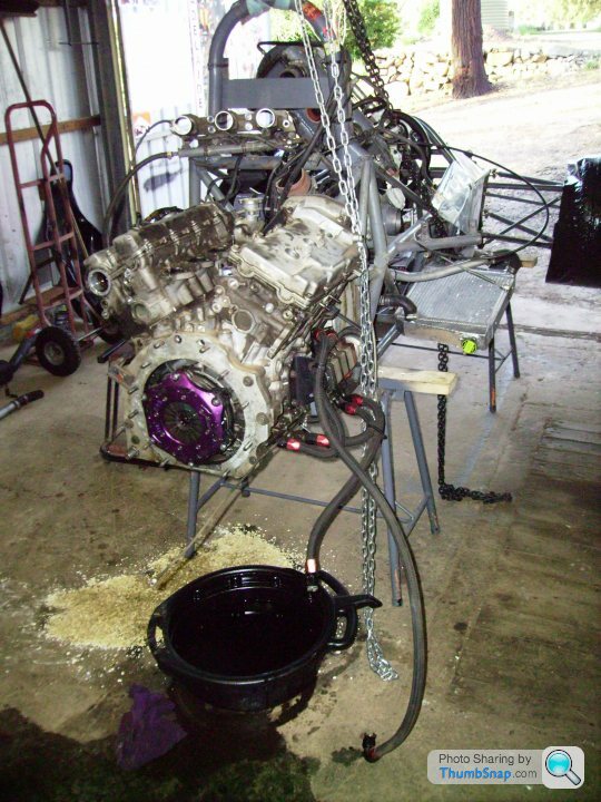
Machined the bore of a spare 4 cyl civic flywheel to suit the J35, the bolt pitch is the same but count is different (6 on civic, 8 on the V6) so only 2 bolt holes align, but they will cope OK with the cranking torque, at this stage it is only an unloaded test engine. The starter is from a J30 odyssey, it matches the civic ring gear but turns in the correct direction.
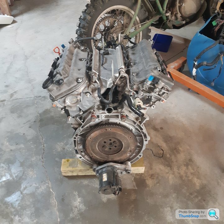
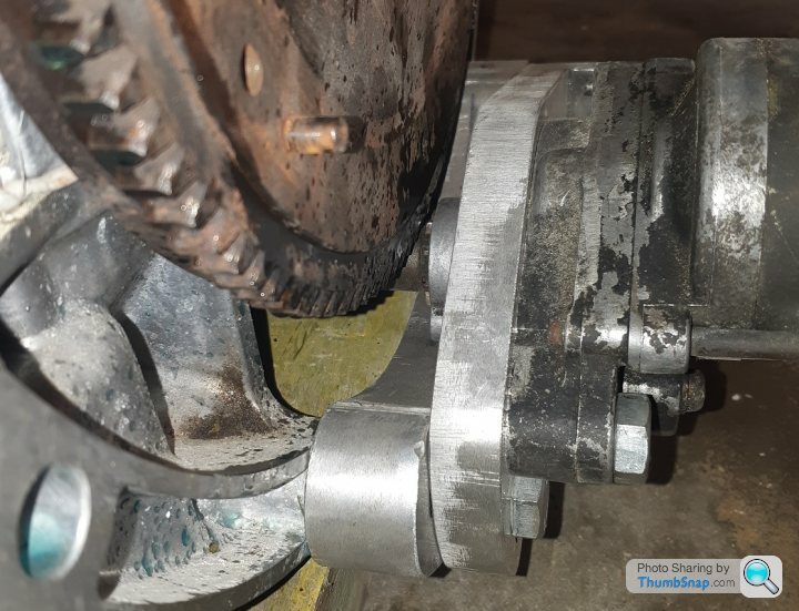
Machined some aluminium plate to make a starter motor mount as I don't have/need the transmission for the V6. It is made in 2 pieces, with an adjustment slot so that the correct ring gear tooth engagement is easily set.
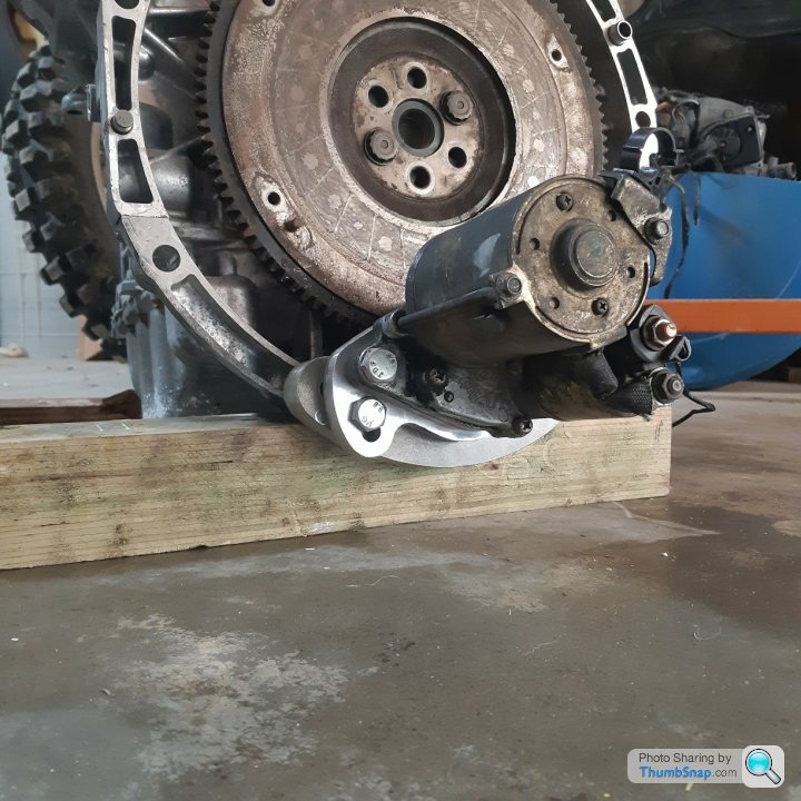
tight fit with minimal clearance on the pinion when disengaged.
The good news is it cranks over strongly - all it needs is a support frame, fuel supply, hacked up cooling system and ignition loom to be able to generate some excessive noise and flames - will post that milestone on youtube
Spent a few hours prepping the test motor for its imminent first fire-up. Had to understand and measure the crankshaft position sensor (CKP) signal and how the signal is produced on the 60-2 wheel, especially the angular offset between the first tooth after the gap and TDC of no.1 cylinder.
12V or 14V feed makes no difference to the output signal;
This is the 2 tooth gap that the ECU detects
Once the first tooth after the gap is sensed by the hall sensor the signal drops from 3.3V to zero, the falling edge at this angle is used to synchronise the ECU so that the firing of the ignition coils (Coil on Plug type using 5V signal) and injectors matches the true mechanical positions.
Machined the bore of a spare 4 cyl civic flywheel to suit the J35, the bolt pitch is the same but count is different (6 on civic, 8 on the V6) so only 2 bolt holes align, but they will cope OK with the cranking torque, at this stage it is only an unloaded test engine. The starter is from a J30 odyssey, it matches the civic ring gear but turns in the correct direction.
Machined some aluminium plate to make a starter motor mount as I don't have/need the transmission for the V6. It is made in 2 pieces, with an adjustment slot so that the correct ring gear tooth engagement is easily set.
tight fit with minimal clearance on the pinion when disengaged.
The good news is it cranks over strongly - all it needs is a support frame, fuel supply, hacked up cooling system and ignition loom to be able to generate some excessive noise and flames - will post that milestone on youtube
Gassing Station | Readers' Cars | Top of Page | What's New | My Stuff