Discussion


Camaro said:
That shows the wonders of the Youtube algorithms, I've already Subscribed to your channel but not seen any of these updates!
Yeah youtube doesn’t like my content for whatever reason. Latest video was only uploaded yesterday and seems to be doing better at the moment
Thanks for subscribing
Thanks for the encouraging comments, I appreciate it considering the amount of work that’s been put into this car.
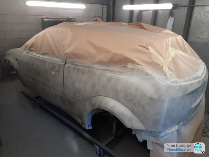
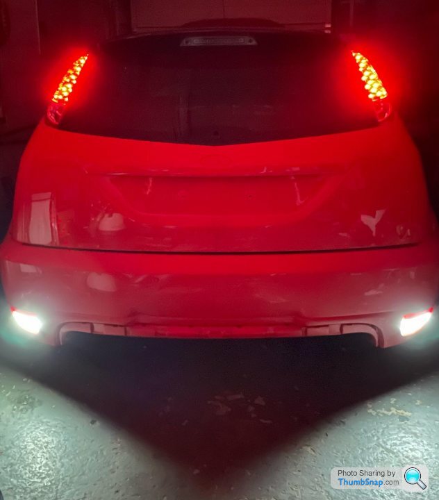
I’m well happy with the colour too. It’s not anywhere near finished yet but at least putting the outside together and getting to see the fruits of a fair bit of labour has been worth every second
I can’t stop looking at it lol
I’m well happy with the colour too. It’s not anywhere near finished yet but at least putting the outside together and getting to see the fruits of a fair bit of labour has been worth every second
I can’t stop looking at it lol
3 months again - I swear I don’t do it on purpose, I just get an itch to check up on here to let everyone know how it’s coming along!
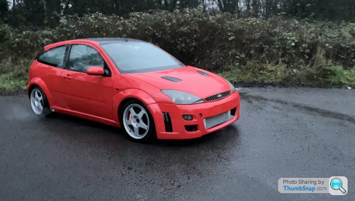
Doesn’t look like I’ve done much, but I’ve done loads. It’s acting like a car now instead of something thrown together for a quick video before Christmas
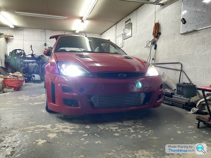
Doesn’t look like I’ve done much, but I’ve done loads. It’s acting like a car now instead of something thrown together for a quick video before Christmas
RobXjcoupe said:
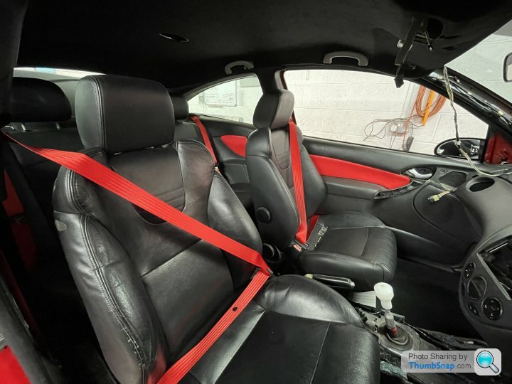
That drivers seat, you need to carefully steam that bolster to plump it up and lose that crease. I was looking for good seats for my own mk1 focus (not as nice as yours)
In the end I just reupholstered what I had. Picture below. Just used original standard seats

Yeah I’ll sort them out at some point. That’s low hanging fruit for a weekend when the car all works though In the end I just reupholstered what I had. Picture below. Just used original standard seats

I know, i know, twice in one month, what's wrong with me?
well, i need some help!
first of all, can anyone identify what kind of signal this is...
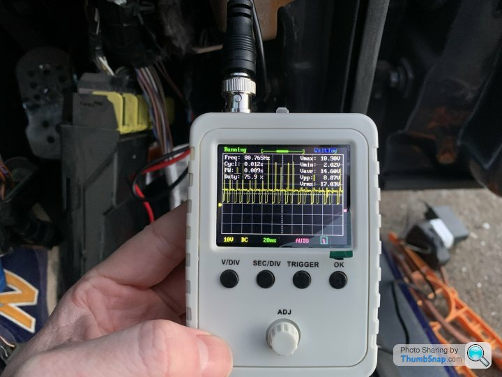
Its the tacho output from one of the ignitors on the 1uz and I would like to read it with an Arduino so I can work some magic with it.
obviously being the tacho signal it will change with engine revolutions but the above was taken at idle. I don't know if its a PWM signal (unlikely) or just a simple drop to earth every time the ignitor fires. if someone knows how I can read that with an Arduino that will be much help.
Also if anyone knows how J1850PWM CAN protocol used by Ford as part of their SCP in the 90's early 00's before CAN was standardised across manufacturers works id love to pick your brains. I've worked a lot of it out and I can communicate with the dash with varying degrees of success, id just like it to be a little more successful
well, i need some help!
first of all, can anyone identify what kind of signal this is...
Its the tacho output from one of the ignitors on the 1uz and I would like to read it with an Arduino so I can work some magic with it.
obviously being the tacho signal it will change with engine revolutions but the above was taken at idle. I don't know if its a PWM signal (unlikely) or just a simple drop to earth every time the ignitor fires. if someone knows how I can read that with an Arduino that will be much help.
Also if anyone knows how J1850PWM CAN protocol used by Ford as part of their SCP in the 90's early 00's before CAN was standardised across manufacturers works id love to pick your brains. I've worked a lot of it out and I can communicate with the dash with varying degrees of success, id just like it to be a little more successful
Fastdruid said:
*crunches knuckles*....
Right then, lets consult my big load of notes...
Tacho is 4-cylinder type as the 1UZ ign system is in effect two 4 cylinder engines (two ign generations/coils/dizzys), tacho signal is a simple mirror of the coil input. Pretty trivial to work with.
J1850PWM isn't CAN. Or at least it isn't CANBUS (we can argue all day if it is a Controller Area Network) , I've had a play with Mazda ISO 15765-4 CAN but that is trivial as you can buy CAN transceivers. You can use an ELM327 to communicate and they're pretty easy to use to scan data. If you get a USB ELM327 and connect via a serial terminal you can manually set the settings to what you want and just dump all the activity on the bus. Trouble is there that you need a "live" car to do it on and as far as I'm aware you don't have one.... If you have a Focus you can borrow then commands for the ELM327 are here.
https://www.elmelectronics.com/wp-content/uploads/...
To read J1850 PWM I'd do this (notes on what the commands do with the # lines
# Reset
AT Z
# Set 115.2kbps
AT PP 0C SV 23
# Turn on 115.2 setting
AT PP 0C ON
# Reset
AT Z
# Disable in-frame responses (not really needed tbh)
AT IFR0
# Monitor all messages
AT MA
Can then play about with looking at the data.
As for writing it the advantage as the J1850 PWM as a 5V bus you can use an arduino easily, disadvantage is you may need to bit bang. I've never tried as CAN is *way* easier.
I just called J1850 a CAN as it would hopefully make the most sense to people. call it Ford SCP or the 2 wires that let the car talk to itself for all I care I'm just glad someone knows what I'm talking about when I say J1850 😁Right then, lets consult my big load of notes...
Tacho is 4-cylinder type as the 1UZ ign system is in effect two 4 cylinder engines (two ign generations/coils/dizzys), tacho signal is a simple mirror of the coil input. Pretty trivial to work with.
J1850PWM isn't CAN. Or at least it isn't CANBUS (we can argue all day if it is a Controller Area Network) , I've had a play with Mazda ISO 15765-4 CAN but that is trivial as you can buy CAN transceivers. You can use an ELM327 to communicate and they're pretty easy to use to scan data. If you get a USB ELM327 and connect via a serial terminal you can manually set the settings to what you want and just dump all the activity on the bus. Trouble is there that you need a "live" car to do it on and as far as I'm aware you don't have one.... If you have a Focus you can borrow then commands for the ELM327 are here.
https://www.elmelectronics.com/wp-content/uploads/...
To read J1850 PWM I'd do this (notes on what the commands do with the # lines
# Reset
AT Z
# Set 115.2kbps
AT PP 0C SV 23
# Turn on 115.2 setting
AT PP 0C ON
# Reset
AT Z
# Disable in-frame responses (not really needed tbh)
AT IFR0
# Monitor all messages
AT MA
Can then play about with looking at the data.
As for writing it the advantage as the J1850 PWM as a 5V bus you can use an arduino easily, disadvantage is you may need to bit bang. I've never tried as CAN is *way* easier.
I've also maybe been a little disingenuous in my original question by not explaining everything, so here goes...
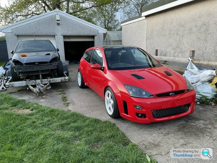
I have a few packets of data from a friend who has probably done what you suggest above to give me a bunch of data to work with, and tbh if I needed more it probably wouldn't be too hard to get the spare up and running for long enough to get more sweet sweet bytes from that proprietary network
Poor thing is looking sorry for itself sat next to that sexy looking red thing...
anyway, with these packets of frames we have managed to decipher how some of it works, ill explain briefly for those uninitiated.
you might have a frame of data that looks like this;
81 1B 10 25 12 6A 02 CE 00 11
and I know in general the first 3 bytes are the header, in the header you get priority, then destination for the frame, then the source of the frame, in this case I happen to know 81 is high priority, 1B is the tacho gauge on the cluster and 10 is the ECU. The last byte is seemingly always a checksum based on a polynomial equation, and the bits in between are ... well ... gibberish.
I have managed to work out that if you send a byte of 25 and then a byte of hex ranging between 2 specific numbers the tacho will spring into life and in this instance but as for the 6A 02 CE and 00 I am totally at a loss. which is what I was hoping for help with
(you know someone who worked on this stuff in the 90's might have some documentation laying around that they accidently upload into an email and send it to a stranger on the internet, stranger things have happened)
because whilst I know the malfunction light address, the tachometer, the speedo, the mileage counter & the coolant gauge, I still don't know the battery light, EML and any other interesting destinations. Knowing those would be a great help towards the end goal.
So as I said, I can get the dash to jump around and do a little dance based on the codes I send from an Arduino, what I cant seem to do is send them quick enough (I'm hoping my recent purchase of multiple Arduino Nano's solves this) and if I'm missing something in the packet of data I just mentioned that I should be sending beyond the first 2 bytes after the header. Progress is being made there though I guess, I'm just hoping someone can help me hurry it along 😊
of course, once I have achieved that and know how and what to send to the dash, I need to code the Arduino too do that based on real world conditions, so the analogue read of a ohmic value for the coolant temp sensor is probably an easy one, but nothing is more satisfying and gives more instant gratification that having a tacho dance to the tune of my foot on the pedal. to get that hit of dopamine I need to understand how to get the Arduino to recognise the signal I posted in my previous post, which tbh, I'm still none the wiser as to what it is.
I know its 12v at its peak and I know its pulsing at a frequency of 80hz, but what's the significance of that pulse and how to I tell the Arduino that that = ~1000 rpm?! I know I'm going to have to drop the voltage down to 5v so I don't fry the Arduino so that would imply using a voltage splitter but that would then make my current readings all wrong....
... im just gonna have to split the voltage and chuck the scope on it again aren't I...
I promise I don't wait 3 months between updates on purpose - I guess I'm just Lazy!
either way its been on the dyno
massive disappointment
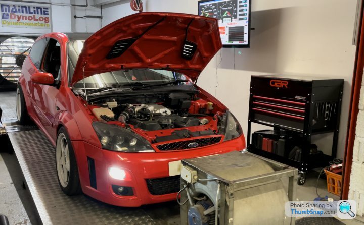
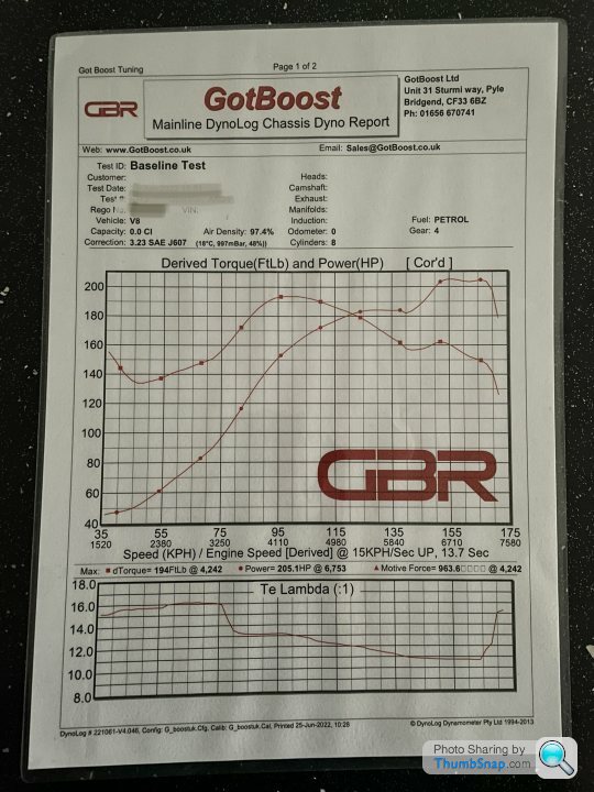
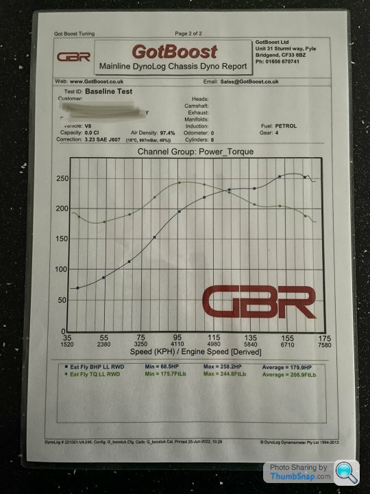
Standard engine management having a fit when it see's boost
so next upgrades are standalone ECU and custom dash so I don't have to mess about with any of that Ford nonsense
either way its been on the dyno
massive disappointment
Standard engine management having a fit when it see's boost
so next upgrades are standalone ECU and custom dash so I don't have to mess about with any of that Ford nonsense
Gassing Station | Readers' Cars | Top of Page | What's New | My Stuff