1969 Lotus Elan S4 SE Basket case revival
Discussion


Hi Lotusgone, re: the greying rocker switches - Paul at UKsport cars recommended brake fluid! I will try to polish them using some "Curator Clock Case Restorer" which can be used for restoring Bakelite and plastics. I have some ready for a 1930s valve radio project I have planned for the far future!
Hi Cambs_Stuart, the Body work has started, after 2 guys spent 3 days battling with sanding they gave up - the paint was rock hard and constantly clogging the sandpaper, so it went for soda blasting. Apparently it is pretty good underneath and only one new repair was found at the front, but this one has been well repaired so does not need further work. Here is a taster of the car coming back from the blasters- I will get some more photos later this week,

Hi Cambs_Stuart, the Body work has started, after 2 guys spent 3 days battling with sanding they gave up - the paint was rock hard and constantly clogging the sandpaper, so it went for soda blasting. Apparently it is pretty good underneath and only one new repair was found at the front, but this one has been well repaired so does not need further work. Here is a taster of the car coming back from the blasters- I will get some more photos later this week,
Regarding the chroming on the inside of the lamps, I've had decent enough results with adhesive silver foil tape. If it's applied carefully, without creases, you can smooth it down so it gets a good reflective finish.
It's easy to form over curves etc and you can trim it to the size you need for awkward places. Once the lens/diffuser is in place and you've got decent bulbs in, it's a good improvement and a low cost fix.
It's easy to form over curves etc and you can trim it to the size you need for awkward places. Once the lens/diffuser is in place and you've got decent bulbs in, it's a good improvement and a low cost fix.
ReverendCounter said:
Regarding the chroming on the inside of the lamps, I've had decent enough results with adhesive silver foil tape. If it's applied carefully, without creases, you can smooth it down so it gets a good reflective finish.
It's easy to form over curves etc and you can trim it to the size you need for awkward places. Once the lens/diffuser is in place and you've got decent bulbs in, it's a good improvement and a low cost fix.
Cheers Reverend. My original comments were about the external chrome trim on the lamps, but looking back at them after reading your post, some silver foil may well help on the inside too. I have a roll from when I applied it to the back lit number plate on my old TVR.It's easy to form over curves etc and you can trim it to the size you need for awkward places. Once the lens/diffuser is in place and you've got decent bulbs in, it's a good improvement and a low cost fix.
Here is the Chimaera number plate lighting before

And here is the difference with some foil and LED bulbs!

Edited by Spunagain on Wednesday 31st August 08:30
williamp said:
Regarding the inner tubes, worth checking. On my Aston, even though the tyres were new, the wheels were of such a design that they needed inner tubes to be safe. Worth asking if Lotus wheels need them..
Cheers for this, I asked teh question on the Elan FB page and I got a lot of different answers and so then did what I should have done and checked the workshop manual which states:Lotus Elan Workshop Manual said:
Tyres — Type — All models:
Firestone F.100 tubeless
Goodyear G.800 with tubes
Dunlop SP.Sport with tubes
So I will stick with tubeless for now!Firestone F.100 tubeless
Goodyear G.800 with tubes
Dunlop SP.Sport with tubes
I also got some more pictures of the body as it is today - body tub:

Doors, lids and bumpers - the front bumper will be replaced I think:

Edited by Spunagain on Thursday 1st September 13:40


Hi Reverend,
The camera is making it look much brighter than it is, but I was very careful in the TVR which has gone now to pay for the Lotus!
I have been making slow but steady progress so time for some updates:
Front Suspension
I got the refurbished front hubs dismantled again and reassembled with the trunnions and mounted on the wishbones. The rear wishbones were also hung after cleaning out the powder coat from the chassis mounts.
I fitted the anti-roll bar bushes which were challenging - one went in fine, pressed in with with plank of plywood drilled with a notch to make a “pusher” and a good dose of WD40- the other did not want to play and I confess that I got help from the local garage.
The steering rack arrived back and it needed a new rack and pinion, so was more expensive than I had planned - a recurring theme This is now fitted with new track rod ends. I added the anti roll bar and the front suspension is done bar the brake callipers!
While doing all of these bits I found I was missing a number of nuts, bolts and lock washers so ordered them in, which allowed fitting of the front shocks to the hubs and final hanging of the diff.

Rear hubs
I got the old rear shock inserts out of the rear hubs and cleaned them up and dropped off at the local garage to press out the wheel bearings. But even with 5 tonnes of pressure they were in danger of damaging the garages press tools, so I ordered a hub removal tool from SJ Sportscars even with a blow torch and my long torque wrench I could not undo it so back to Speen garage and with their big boy toys and the correct tool the hubs are finally split!

The Workshop manual is a bit vague about assembling the rear drive shafts and hubs and there is some good advice on the Elan forums but I was still a little unsure. I put together how I think everything goes together and got some more guidance from the Facebook group to come up with this which worked for me with this updated diagram:

1) Outer Bearing (closest to the spider) to shaft
Freeze Drive-shafts in a plastic bag in the domestic freezer overnight.
Warm the bearing and spacer in the oven to 130°C (Fan!) (I tried 100°C which was not hot enough) and using a heat gun, get your wife to keep them warm while you grab the drive shafts out of the freezer.
Give the driveshafts a quick squirt with WD40.
Then “simply” (and I really mean simply) drop the spacer onto the drive shaft followed by the bearing.
Press only on the inner race of the outer bearing if needed. (I didn’t).
Fit smaller Circlip ‘A’ to hold the bearing onto the shaft. (Make sure tapers in the circlip's plier holes are small side outwards!) And make sure the space is central.
2) Inner Bearing (closest to wheel)
Freeze the Inner bearing.
Warm the aluminium bearing housing until spit boils off – I used a blowtorch.
Then fit Inner bearing into aluminium bearing housing.
Press only on the outer race of the inner bearing if needed.
Loctite the bearing in place - careful not to get any into the bearing.
Fit the large Circlip ‘B’ (ensuring the ones supplied are not too big before you start!)
![]()
3) Fit the shaft into the Bearing housing
Freeze the Shaft and bearing assembly
Warm the Bearing housing and the hub again hot enough to boil off water drops
Install the shaft and bearing assembly into the Bearing housing from the rear whilst supporting the inner bearing on the inner race with a tube long enough to accept the drive taper - I used some plastic plumbing tube I had lying around.
Fit the hub according to instructions that came with the drive shafts, fit the bolt and torque up.
This did the trick and the hubs are both turning nice and smoothly.
I then bolted the hub assemblies to the rear A frames and fitted the new shockers into the shock tubes in a bath of gear oil. Then fitted the powder coated springs and spring mounts and with a new set of spring compressors fitted them to the hubs.
I then bolted in the new driveshafts but the bolts at the diff end touch the diff housing so I have ordered some 7/16 spring washers to set them back a bit. Still a bit of a milestone:

Propshaft
The propshaft UJs resisted my hammering and so also got dropped off for pressing out. I cleaned and painted them and got the local garage to fit the new UJs.
The nose of the UJ was badly pitted so I replaced it and am using the old one to plug the gearbox for now as hammerite is not a good seal surface!
Some dashboard bits
I also dismantled the Dashboard, pressing out the mounting bolt bushes with a vice and some small sockets and removing the glove box hinges for fitting to the new woodwork from Classical Dash. I also cleaned up and painted the glove box brackets.
I also cleaned up the tacho - removing some stray plastic from behind the glass - a mounting for one of the connections has broken and I will replace it with a rubber grommet, and I ordered some new seals for it. The front bezel was of course bonded in with some sort of sealant which made it so much harder to remove.
On closer inspection the fuel gauge display was very scabby with peeling paint and decided to try a quick tidy up. First, lift the bezel tabs and remove the front glass, prise out the flaky top part of the display, then unscrew the mechanism from the back and then remove it from the front along with the scale panel. I checked the mechanism was ok with a multimeter.

Stripped the flakey panel and wire brushed and masked the casing:

Primed it -the photo is taken straight after I sprayed it - it was flat after it had dried:

Matt black paint on the dial and spray Hammerite on the case, plus a new seal:

I then applied a new sticker for my fuel gauge. Unfortunately I lost the “Smiths” logo, but I think it looks ok.

I also had a crack at the rocker switches and Curator Clock Case Restorer and Autoglym polish did not make a dent, but the PCB soldering heat gun at work set to 450C did! I have ordered some dielectric grease and will dismantle, clean and re-grease them all as well.
Edit: I don't recommend you do this, it looks like it caused the surface to ripple a bit and possible bake in some fading. See a later post for a better way!

I also stripped the pedal box, cleaned and painted it and put it back together with some new rubbers. I also dismantled, cleaned and re-greased the brake pedal switch which tested ok but best to do while it is easy to get at.

I was also missing the gear stick and knob. I photographed one at a classic show and made a few measurements and a drawing and my boss's dad turned this up on his lathe in stainless steel. I added a cheap wooden gear knob from Ebay while I keep an eye out for an original one..

The Brake callipers arrived back so I could start fitting them, but the copper hard lines I ordered are way too long! So I borrowed a friend's brake pipe cutting and flaring kit and will do them next.
The rear callipers came back without the handbrake mechanism so I have chased that up and that should arrive soon!
And I have got the wrong front brake pads - I need larger ones - it is possible I have +2 brake callipers!
Other updates - it appears that the DVLA are taking a harder line on EV conversions and now insisting on getting an inspection done by a third party at the DVLA’s expense. A guy doing a Mini drilled six 8mm holes in the boot of his car to mount batteries and this has counted as a modification to the chassis/monocoque and he has been told to do an IVA! While it is technically ok to modify the body of a chassis based car, I think I will try and avoid it so I will route the HV cables from the boot through the sills and out of the old heater hose holes through the firewall bit in some solid trunking to avoid any new holes.
Still no news or replies to email or voice messages on the adapter plate - it looks like I may have to find another supplier.
The body is now prepped for paint and should be ready in 3-4 weeks. I need to get a wriggle on!


The camera is making it look much brighter than it is, but I was very careful in the TVR which has gone now to pay for the Lotus!
I have been making slow but steady progress so time for some updates:
Front Suspension
I got the refurbished front hubs dismantled again and reassembled with the trunnions and mounted on the wishbones. The rear wishbones were also hung after cleaning out the powder coat from the chassis mounts.
I fitted the anti-roll bar bushes which were challenging - one went in fine, pressed in with with plank of plywood drilled with a notch to make a “pusher” and a good dose of WD40- the other did not want to play and I confess that I got help from the local garage.
The steering rack arrived back and it needed a new rack and pinion, so was more expensive than I had planned - a recurring theme
This is now fitted with new track rod ends. I added the anti roll bar and the front suspension is done bar the brake callipers!While doing all of these bits I found I was missing a number of nuts, bolts and lock washers so ordered them in, which allowed fitting of the front shocks to the hubs and final hanging of the diff.
Rear hubs
I got the old rear shock inserts out of the rear hubs and cleaned them up and dropped off at the local garage to press out the wheel bearings. But even with 5 tonnes of pressure they were in danger of damaging the garages press tools, so I ordered a hub removal tool from SJ Sportscars even with a blow torch and my long torque wrench I could not undo it so back to Speen garage and with their big boy toys and the correct tool the hubs are finally split!
The Workshop manual is a bit vague about assembling the rear drive shafts and hubs and there is some good advice on the Elan forums but I was still a little unsure. I put together how I think everything goes together and got some more guidance from the Facebook group to come up with this which worked for me with this updated diagram:
1) Outer Bearing (closest to the spider) to shaft
Freeze Drive-shafts in a plastic bag in the domestic freezer overnight.
Warm the bearing and spacer in the oven to 130°C (Fan!) (I tried 100°C which was not hot enough) and using a heat gun, get your wife to keep them warm while you grab the drive shafts out of the freezer.
Give the driveshafts a quick squirt with WD40.
Then “simply” (and I really mean simply) drop the spacer onto the drive shaft followed by the bearing.
Press only on the inner race of the outer bearing if needed. (I didn’t).
Fit smaller Circlip ‘A’ to hold the bearing onto the shaft. (Make sure tapers in the circlip's plier holes are small side outwards!) And make sure the space is central.
2) Inner Bearing (closest to wheel)
Freeze the Inner bearing.
Warm the aluminium bearing housing until spit boils off – I used a blowtorch.
Then fit Inner bearing into aluminium bearing housing.
Press only on the outer race of the inner bearing if needed.
Loctite the bearing in place - careful not to get any into the bearing.
Fit the large Circlip ‘B’ (ensuring the ones supplied are not too big before you start!)
3) Fit the shaft into the Bearing housing
Freeze the Shaft and bearing assembly
Warm the Bearing housing and the hub again hot enough to boil off water drops
Install the shaft and bearing assembly into the Bearing housing from the rear whilst supporting the inner bearing on the inner race with a tube long enough to accept the drive taper - I used some plastic plumbing tube I had lying around.
Fit the hub according to instructions that came with the drive shafts, fit the bolt and torque up.
This did the trick and the hubs are both turning nice and smoothly.
I then bolted the hub assemblies to the rear A frames and fitted the new shockers into the shock tubes in a bath of gear oil. Then fitted the powder coated springs and spring mounts and with a new set of spring compressors fitted them to the hubs.
I then bolted in the new driveshafts but the bolts at the diff end touch the diff housing so I have ordered some 7/16 spring washers to set them back a bit. Still a bit of a milestone:
Propshaft
The propshaft UJs resisted my hammering and so also got dropped off for pressing out. I cleaned and painted them and got the local garage to fit the new UJs.
The nose of the UJ was badly pitted so I replaced it and am using the old one to plug the gearbox for now as hammerite is not a good seal surface!
Some dashboard bits
I also dismantled the Dashboard, pressing out the mounting bolt bushes with a vice and some small sockets and removing the glove box hinges for fitting to the new woodwork from Classical Dash. I also cleaned up and painted the glove box brackets.
I also cleaned up the tacho - removing some stray plastic from behind the glass - a mounting for one of the connections has broken and I will replace it with a rubber grommet, and I ordered some new seals for it. The front bezel was of course bonded in with some sort of sealant which made it so much harder to remove.
On closer inspection the fuel gauge display was very scabby with peeling paint and decided to try a quick tidy up. First, lift the bezel tabs and remove the front glass, prise out the flaky top part of the display, then unscrew the mechanism from the back and then remove it from the front along with the scale panel. I checked the mechanism was ok with a multimeter.
Stripped the flakey panel and wire brushed and masked the casing:
Primed it -the photo is taken straight after I sprayed it - it was flat after it had dried:
Matt black paint on the dial and spray Hammerite on the case, plus a new seal:
I then applied a new sticker for my fuel gauge. Unfortunately I lost the “Smiths” logo, but I think it looks ok.
I also had a crack at the rocker switches and Curator Clock Case Restorer and Autoglym polish did not make a dent, but the PCB soldering heat gun at work set to 450C did! I have ordered some dielectric grease and will dismantle, clean and re-grease them all as well.
Edit: I don't recommend you do this, it looks like it caused the surface to ripple a bit and possible bake in some fading. See a later post for a better way!
I also stripped the pedal box, cleaned and painted it and put it back together with some new rubbers. I also dismantled, cleaned and re-greased the brake pedal switch which tested ok but best to do while it is easy to get at.
I was also missing the gear stick and knob. I photographed one at a classic show and made a few measurements and a drawing and my boss's dad turned this up on his lathe in stainless steel. I added a cheap wooden gear knob from Ebay while I keep an eye out for an original one..
The Brake callipers arrived back so I could start fitting them, but the copper hard lines I ordered are way too long! So I borrowed a friend's brake pipe cutting and flaring kit and will do them next.
The rear callipers came back without the handbrake mechanism so I have chased that up and that should arrive soon!
And I have got the wrong front brake pads - I need larger ones - it is possible I have +2 brake callipers!
Other updates - it appears that the DVLA are taking a harder line on EV conversions and now insisting on getting an inspection done by a third party at the DVLA’s expense. A guy doing a Mini drilled six 8mm holes in the boot of his car to mount batteries and this has counted as a modification to the chassis/monocoque and he has been told to do an IVA! While it is technically ok to modify the body of a chassis based car, I think I will try and avoid it so I will route the HV cables from the boot through the sills and out of the old heater hose holes through the firewall bit in some solid trunking to avoid any new holes.
Still no news or replies to email or voice messages on the adapter plate - it looks like I may have to find another supplier.
The body is now prepped for paint and should be ready in 3-4 weeks. I need to get a wriggle on!
Edited by Spunagain on Tuesday 17th January 08:39
Small update today: the Tony Thompson drive shafts needed a little fettling to avoid the different parts locking together on full suspension drop and this was done with the Dremel and a deburring tool. Now the rear wheels go right round!
Time for some brakes.
The hand brake mechanism arrived back with new parts but not cleaned up so I had a go at that:
As they arrived:

Cleaned, painted, greased and installed, just waiting on new pins.

The new front pads I got did not fit so as there was plenty of meat on them, I took the old brake pads cleaned them up and painted in high temperature paint. However I dropped one and it broke apart like a dropped biscuit so some more research was done and it seems my front brakes have been upgraded to Elan +2S standard with the larger 78mm wide pads. I have ordered some from EBC.
First three coats of high build primer on the body:


Much flatting filling and then three more to go!
Time for some brakes.
The hand brake mechanism arrived back with new parts but not cleaned up so I had a go at that:
As they arrived:
Cleaned, painted, greased and installed, just waiting on new pins.
The new front pads I got did not fit so as there was plenty of meat on them, I took the old brake pads cleaned them up and painted in high temperature paint. However I dropped one and it broke apart like a dropped biscuit so some more research was done and it seems my front brakes have been upgraded to Elan +2S standard with the larger 78mm wide pads. I have ordered some from EBC.
First three coats of high build primer on the body:
Much flatting filling and then three more to go!

Body work is coming on 
Body in primer - what a difference…
From this:

To this:


The company in Oz has been back in touch and they have had problems with their metalwork supplier - my adapter plate is in a big delayed order and the latest shipping date was due to be last week! I am thinking now to get the rest of the car complete and do the drive and batteries at the end.
I have managed to get a lightly used (only 300 miles) 2 part heavy duty Helix clutch assembly which has saved me a few hundred pounds - it is like new! It might be a bit heavy, but we shall see!
Also the prop-shaft is assembled, greased and bolted in along with the new gearbox mount.
More shiny things arrived this week with new Speedo and temperature gauges, you can see the full set now including the engine temp sensor I found at an auto-jumble.

The Dash should be ready in a couple of weeks too.
My attempts at brake pipe flaring failed so got them done by the pros and the new front pads arrived and were fitted, along with the Christmas tree (Handbrake mechanism) in. Just waiting for a pair of clevis pins to complete the brake system.
I stripped the hand brake cable off the hand brake and tidied it up and then decided to just buy a new brake cable as the old one is bound to have stretched.
Handbrake out of the car:

Handbrake dismantled and wire-bushed clean:

Handbrake painted and reassembled - just need to add the handbrake light switch which is on order - old one was knackered!
Chassis soundproofing cover marking up:


This was pointless as the original cover did not match the holes so I had to re-cut them on the car after I had glued it all down!
Wheels on with the soundproofing cover glued on:

Bar the clevis pins for the handbrake activation rods, I am now ready to drop the body on when it arrives!
Next I started to have a look at the window motors. While they actually worked quite well they looked a bit iffy, with rust attacking one quite badly - this is the better one - I forgot to photograph the other one before I wire brushed it:

I removed the casings and gave them a good wire brushing:

I have added some rust converter and am waiting for that to cure. I will paint them tomorrow.
I pulled the motor rotors out and removed the hardened grease and cleaned up the commutators (untreated on the right) and then re-greased:

The brushes are in good condition and I just cleaned them up with some contact cleaner and re-greased the gearing.
And finally now the body is in colour - 3 more coats and curing and compounding next


And engine bay done in black:

And the whole body with added stone-chip, (not compounded yet):

While waiting for the body, next few jobs on my list is to:
Body in primer - what a difference…
From this:
To this:
The company in Oz has been back in touch and they have had problems with their metalwork supplier - my adapter plate is in a big delayed order and the latest shipping date was due to be last week! I am thinking now to get the rest of the car complete and do the drive and batteries at the end.
I have managed to get a lightly used (only 300 miles) 2 part heavy duty Helix clutch assembly which has saved me a few hundred pounds - it is like new! It might be a bit heavy, but we shall see!
Also the prop-shaft is assembled, greased and bolted in along with the new gearbox mount.
More shiny things arrived this week with new Speedo and temperature gauges, you can see the full set now including the engine temp sensor I found at an auto-jumble.
The Dash should be ready in a couple of weeks too.
My attempts at brake pipe flaring failed so got them done by the pros and the new front pads arrived and were fitted, along with the Christmas tree (Handbrake mechanism) in. Just waiting for a pair of clevis pins to complete the brake system.
I stripped the hand brake cable off the hand brake and tidied it up and then decided to just buy a new brake cable as the old one is bound to have stretched.
Handbrake out of the car:
Handbrake dismantled and wire-bushed clean:
Handbrake painted and reassembled - just need to add the handbrake light switch which is on order - old one was knackered!
Chassis soundproofing cover marking up:
This was pointless as the original cover did not match the holes so I had to re-cut them on the car after I had glued it all down!
Wheels on with the soundproofing cover glued on:
Bar the clevis pins for the handbrake activation rods, I am now ready to drop the body on when it arrives!
Next I started to have a look at the window motors. While they actually worked quite well they looked a bit iffy, with rust attacking one quite badly - this is the better one - I forgot to photograph the other one before I wire brushed it:
I removed the casings and gave them a good wire brushing:
I have added some rust converter and am waiting for that to cure. I will paint them tomorrow.
I pulled the motor rotors out and removed the hardened grease and cleaned up the commutators (untreated on the right) and then re-greased:
The brushes are in good condition and I just cleaned them up with some contact cleaner and re-greased the gearing.
And finally now the body is in colour - 3 more coats and curing and compounding next
And engine bay done in black:
And the whole body with added stone-chip, (not compounded yet):
While waiting for the body, next few jobs on my list is to:
- Complete the window motors
- Clean, paint and re-grease the window mechanisms
- Fix wiper mechanism
- Look at the dashboard switch innards
- Clean and modify the heater box
- Clean and paint the steering column
Edited by Spunagain on Sunday 1st January 09:34
A bit of an electrical heavy refurbishment update this time! II cleaned and painted the window motor casings, greased the bearings and cleaned up the brushes. Once assembled and wired up to the battery the both worked smoothly in both directions. You can see how deep the pitting is, thankfully the casings are properly thick steel:

Next I cleaned and wire brushed the surface rust off the window frames and cleaned out and re-greased the window mechanisms, then replaced the window waist seals with new clips and cleaned and silicone greased the window channel seals. The windows are running nice and smoothly now.

Next up - the wiper mechanism which was locked solid.

I stripped it all down and cleaned off the old grease which had the consistency of Blue-tac and soaked the wheel boxes in petrol which freed up one of them, but while the 2nd could be persuaded to turn but it remained very stiff so I have ordered a new one. Once the Bowden cable was removed the motor worked once connected to the battery, but the parking switch did not work. Opening that up showed a lump of green snot on the parking switch contacts, so that got cleaned up.
I then cleaned the motor brushes (losing the E-clip as it pinged off on removal and disappeared - I know not where, so ordered a new one) and cleaned and re-greased the bearings, gears and Bowden cable. I cleaned the rust off the motor casing and good wheel box casing and gave them a few coats of Hammerite.

Quick tidy up of the brake light switch which was showing an on resistance of about 10Ω. I prised open the lid with a screwdriver:

I took out the washer contact in the middle and cleaned it up and flipped it over and gave it a quick wipe with some dielectric grease:

Now it shows 0.5Ω - much better.
I really wasn’t happy with the state of the dashboard switches even after attacking with the hot air gun.

So I had another go - hand sanding with 400,600,800 and 1200 grit wet and dry paper followed by polishing with a Dremel soft pad got me to this - from left to right: original, 400 grit, 600 grit, 800 grit, 800 grit, 1200 grit, 1200 grit, polished with some car body scratch removal polish:

Then close up photo comparing original cooked one to polished switch:

And all polished:

And after a final polish with Autoglym resin polish, coat of Gtechniq C4 and some Hammerite on the frames before and after:

You can still see some lighter bits but they are deeply embedded in the plastic and even the C4 does not touch them, but they are much better than before! I do not know if this was just age or was made worse by the heat gun, but my recommendation is probably don’t use a heat gun and go with wet and dry paper and polish. It takes ages but does a pretty nice job. The yellow cable ties are to make sure the frame legs do not fall off as they are not very springy and do not all ping back when you reassemble the switches!
I then started the careful process of dismantling the switches and cleaning up the innards, here is the worst, which was one of the electric window switch which started off like this:

Both window switch contacts were showing infinite on-resistance and after cleaning with contact cleaner and 1200 grit wet and dry, and a tiny bit of dielectric greasing (too much and the contacts stuck!), I then tested each closed contact with my multimeter and the worst on-resistance was improved to 0.5Ω - good enough!

Here is the exploded picture of one of the good 3 way switches

When reassembling the headlight switch, one of the little brown cylinders got caught at an angle and shattered. I have bought the only Elan S4 switch on ebay for £22 and planned to replace the hazard and I’ll cannibalise the old one for a good actuator pin. However a mate has just got himself a 3D printer and he was itching to try it out of something useful so I measured up the actuator: The actuator pin is 0.154” diameter 0.263” long, 0.175” pocket depth,0.1” pocket diameter. An in mm: the actuator pin is 3.8mm diameter 6.7mm long, 4.5 pocket depth, 2.6mm pocket diameter. I made a sketch:

Greg then drew it up in CAD:

If anyone else wants to make their own then you can see the design on the Onshape site - the document is public, so you can view and edit it - just need to register for a free account:
https://cad.onshape.com/documents/96d5ee4dc65c13ad...
And then Greg printed some samples:
Google video of the print
Here are the printed actuators along with the broken original:

I cleaned out the spring pockets with a drill bit a bit and popped one into the headlamp switch and tried it out - success - 3.5Ω this is fine as it will only drive a pair of relays as I will also run the sidelights via a relay to keep the strain off the switch.
I then tried 100 on off switch operations and measured again - 3.5Ω and pulled it apart to inspect and it looked unchanged, I’ll call that a win! Cheers Greg!
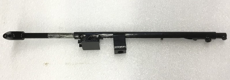
I also gave the steering column and its mounts a good wire brushing, rust treatment and a few coats of Hammerite. I also checked all the column switches with my multimeter and the dip main beam switch worked ok - first time for everything! But the indicator showed infinite resistance for both positions, time to pull it apart, only one nut and bolt to undo:

Inside was horribly grotty:

After a lot of contact cleaner and the dremel wire brush we could see the copper contact wipers and once put back together it was working perfectly:

Having seen the state of the indicator switch, I had a closer look at the Dip/main beam stalk which didn’t unbolt but you could see inside and the contacts were in a much better state so I suspect it has been replaced at some point, a quick squirt of contact cleaner and it was ready for re-installation.
I knew the horn needed a new wire soldering on and a probably a bit of a clean up, so I started pulling it apart. I removed the horn push first which works ok but the clear front is crazed and at £125 it can stay crazed for now. The sprung “pencil” contact between the wheel and static column was worn flat, so a new one was ordered for a tenner.
I cleaned the rust off the spring clip that holds the push and the copper contact ring, and unscrewed the boss for a repaint. Here it is in primer:

I then disassembled the heater box which was full of crud and the heat exchanger also showed signs of leakage.

I drilled out the rivets holding the slow speed resistor and gave it a couple of coats of high temperature paint. The fan motor spewed out large lumps of rust, and I have decided to abandon it for a more modern version - a 7 inch modular fan from Car Builder Solutions. By trimming the spare reinforcing webbing on the outside of the fan housing, it fits snugly into the heater box. The slow speed on the new fan also works well with the original resistor and starts easily in slow speed mode.
I found a pair of 1kW 110V PTC heater modules which will fit in the space left by the old heat exchangers. These are quite clever in that the resistance increases as they get hotter which limits the max temperature. They also have over temperature thermostats fitted which I will experiment to get a safe max operating temperature. This means they only draw enough power to maintain temperature so the max drawn power is proportional to the blower fan speed. Here you can see the fan and a rough idea of where the PTC heaters will be mounted.

I have also found some high temperature adhesive foam to fill the gap between the heater and the box lid from Advanced Seals and Gaskets Limited called EDPM which is rated to 150°C which gives a nice safety margin as I plan to run the heater at around 100°C - close to the original engine coolant temperature.
Next up -
Once the 2nd heater module arrives make-up mounts and try it out!
Drill out the broken bolt in one of the window motor mountings.
Reassemble the steering column.
Look at making up new inter trim pieces as the fibreboard one I have got damp when the garage roof leaked
Next I cleaned and wire brushed the surface rust off the window frames and cleaned out and re-greased the window mechanisms, then replaced the window waist seals with new clips and cleaned and silicone greased the window channel seals. The windows are running nice and smoothly now.
Next up - the wiper mechanism which was locked solid.
I stripped it all down and cleaned off the old grease which had the consistency of Blue-tac and soaked the wheel boxes in petrol which freed up one of them, but while the 2nd could be persuaded to turn but it remained very stiff so I have ordered a new one. Once the Bowden cable was removed the motor worked once connected to the battery, but the parking switch did not work. Opening that up showed a lump of green snot on the parking switch contacts, so that got cleaned up.
I then cleaned the motor brushes (losing the E-clip as it pinged off on removal and disappeared - I know not where, so ordered a new one) and cleaned and re-greased the bearings, gears and Bowden cable. I cleaned the rust off the motor casing and good wheel box casing and gave them a few coats of Hammerite.
Quick tidy up of the brake light switch which was showing an on resistance of about 10Ω. I prised open the lid with a screwdriver:
I took out the washer contact in the middle and cleaned it up and flipped it over and gave it a quick wipe with some dielectric grease:
Now it shows 0.5Ω - much better.
I really wasn’t happy with the state of the dashboard switches even after attacking with the hot air gun.
So I had another go - hand sanding with 400,600,800 and 1200 grit wet and dry paper followed by polishing with a Dremel soft pad got me to this - from left to right: original, 400 grit, 600 grit, 800 grit, 800 grit, 1200 grit, 1200 grit, polished with some car body scratch removal polish:
Then close up photo comparing original cooked one to polished switch:
And all polished:
And after a final polish with Autoglym resin polish, coat of Gtechniq C4 and some Hammerite on the frames before and after:
You can still see some lighter bits but they are deeply embedded in the plastic and even the C4 does not touch them, but they are much better than before! I do not know if this was just age or was made worse by the heat gun, but my recommendation is probably don’t use a heat gun and go with wet and dry paper and polish. It takes ages but does a pretty nice job. The yellow cable ties are to make sure the frame legs do not fall off as they are not very springy and do not all ping back when you reassemble the switches!
I then started the careful process of dismantling the switches and cleaning up the innards, here is the worst, which was one of the electric window switch which started off like this:
Both window switch contacts were showing infinite on-resistance and after cleaning with contact cleaner and 1200 grit wet and dry, and a tiny bit of dielectric greasing (too much and the contacts stuck!), I then tested each closed contact with my multimeter and the worst on-resistance was improved to 0.5Ω - good enough!
Here is the exploded picture of one of the good 3 way switches
When reassembling the headlight switch, one of the little brown cylinders got caught at an angle and shattered. I have bought the only Elan S4 switch on ebay for £22 and planned to replace the hazard and I’ll cannibalise the old one for a good actuator pin. However a mate has just got himself a 3D printer and he was itching to try it out of something useful so I measured up the actuator: The actuator pin is 0.154” diameter 0.263” long, 0.175” pocket depth,0.1” pocket diameter. An in mm: the actuator pin is 3.8mm diameter 6.7mm long, 4.5 pocket depth, 2.6mm pocket diameter. I made a sketch:
Greg then drew it up in CAD:
If anyone else wants to make their own then you can see the design on the Onshape site - the document is public, so you can view and edit it - just need to register for a free account:
https://cad.onshape.com/documents/96d5ee4dc65c13ad...
And then Greg printed some samples:
Google video of the print
Here are the printed actuators along with the broken original:
I cleaned out the spring pockets with a drill bit a bit and popped one into the headlamp switch and tried it out - success - 3.5Ω this is fine as it will only drive a pair of relays as I will also run the sidelights via a relay to keep the strain off the switch.
I then tried 100 on off switch operations and measured again - 3.5Ω and pulled it apart to inspect and it looked unchanged, I’ll call that a win! Cheers Greg!
I also gave the steering column and its mounts a good wire brushing, rust treatment and a few coats of Hammerite. I also checked all the column switches with my multimeter and the dip main beam switch worked ok - first time for everything! But the indicator showed infinite resistance for both positions, time to pull it apart, only one nut and bolt to undo:
Inside was horribly grotty:
After a lot of contact cleaner and the dremel wire brush we could see the copper contact wipers and once put back together it was working perfectly:
Having seen the state of the indicator switch, I had a closer look at the Dip/main beam stalk which didn’t unbolt but you could see inside and the contacts were in a much better state so I suspect it has been replaced at some point, a quick squirt of contact cleaner and it was ready for re-installation.
I knew the horn needed a new wire soldering on and a probably a bit of a clean up, so I started pulling it apart. I removed the horn push first which works ok but the clear front is crazed and at £125 it can stay crazed for now. The sprung “pencil” contact between the wheel and static column was worn flat, so a new one was ordered for a tenner.
I cleaned the rust off the spring clip that holds the push and the copper contact ring, and unscrewed the boss for a repaint. Here it is in primer:
I then disassembled the heater box which was full of crud and the heat exchanger also showed signs of leakage.
I drilled out the rivets holding the slow speed resistor and gave it a couple of coats of high temperature paint. The fan motor spewed out large lumps of rust, and I have decided to abandon it for a more modern version - a 7 inch modular fan from Car Builder Solutions. By trimming the spare reinforcing webbing on the outside of the fan housing, it fits snugly into the heater box. The slow speed on the new fan also works well with the original resistor and starts easily in slow speed mode.
I found a pair of 1kW 110V PTC heater modules which will fit in the space left by the old heat exchangers. These are quite clever in that the resistance increases as they get hotter which limits the max temperature. They also have over temperature thermostats fitted which I will experiment to get a safe max operating temperature. This means they only draw enough power to maintain temperature so the max drawn power is proportional to the blower fan speed. Here you can see the fan and a rough idea of where the PTC heaters will be mounted.
I have also found some high temperature adhesive foam to fill the gap between the heater and the box lid from Advanced Seals and Gaskets Limited called EDPM which is rated to 150°C which gives a nice safety margin as I plan to run the heater at around 100°C - close to the original engine coolant temperature.
Next up -
Once the 2nd heater module arrives make-up mounts and try it out!
Drill out the broken bolt in one of the window motor mountings.
Reassemble the steering column.
Look at making up new inter trim pieces as the fibreboard one I have got damp when the garage roof leaked
Skyedriver said:
By you picked one with a bit of patina there....
Beware of the front suspension turrets. They may look OK but beware. Unless you like a lot of negative camber of course.
Cheers, Skyedriver, when I had the chassis sand blasted, I brought it back home before powder coating and went over it with a fine toothed comb, both suspension towers were in very good nick as the original powder coating has stood up pretty well. Delays on the heater progress as my 2nd PTC heater module was lost in the post!Beware of the front suspension turrets. They may look OK but beware. Unless you like a lot of negative camber of course.
Gassing Station | Readers' Cars | Top of Page | What's New | My Stuff