1969 Lotus Elan S4 SE Basket case revival
Discussion


I spoke to Karl at the Phantom Marine the boat builders in Great Yarmouth and the doors, bonnet, boot lid and light pods are now done, so,I popped over to have a look:
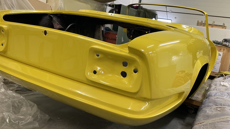

They have done a fabulous job - I am very happy! The colour in the photos is a bit green tinged due to the fluorescent lighting, but in the sunlight it looks fabulous.
Looking at the rollover bar, Karl is much happier fitting it with the car on the chassis so I will arrange to ship it to Norfolk for the body chassis marriage and roll bar fitting once I have the motor in the chassis.
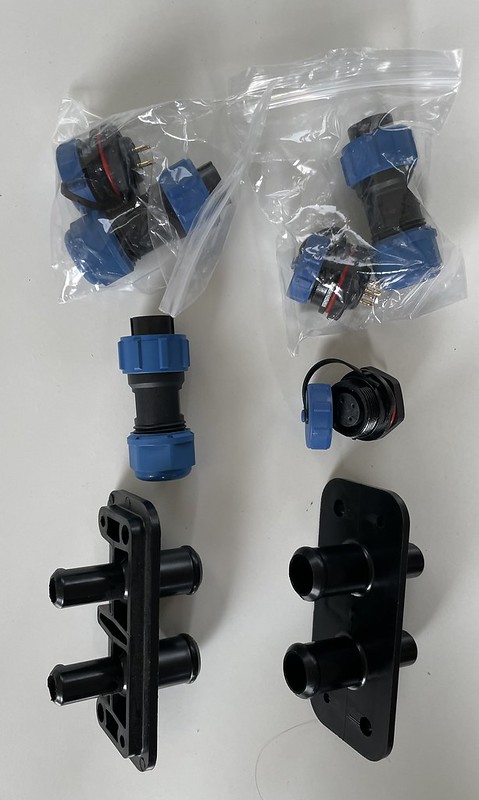
We also discussed the carbon fibre battery boxes and as Karl can make them for a better price and lighter than the American aluminium ones, I have asked him to go ahead and he will measure up once the body is back on the chassis. I have ordered and received the HV bulkhead connectors, battery bus-bars and coolant connectors for those too.
While I was ordering I also ordered the motor potentiometer which will connect directly to the Elans throttle cable and the DC-DC converter which will replace the alternator providing 14V from the main driver battery.

Also I ordered the 4 way connectors for the CAN bus - 3 of them as the can bus loops though one battery box through to the next.
On that note, I have given up with the Australian company for the motor adapter plate after months of missed promises and ignored emails. Last week I had a scaffolder around for some roof works and on spotting the Elan we got chatting about cars and his 1000hp Ford Popular drag car. He recommended John at PJO Engineering in Swindon who has made him adaptor plates to mate various V8s to all sorts of gearboxes, and after a quick visit and chat I have entrusted the work to him.
I ordered the motor so John can check measurements before he starts cutting metal and this has now arrived. John now has the motor drawings, the motor and my gearbox, bellhousing and clutch for measuring up and fabrication. It is great to work with someone who knows their stuff and has a real enthusiasm for it. He is also going to make up the motor mount for me as well!
I also have got the following bits together so John can measure up to make the adapter plate to go between the motor and the bell housing and a coupler which goes between the flywheel and the motor drive shaft:
Clutch housing - got
Clutch plate - got
Clutch release bearing - got
Bearing carrier - got
Release bearing spring fixings - got
6x bolt pressure plate to flywheel - got
6x bolt flywheel to adapter/engine - got
Release bearing D clip - got
Release arm “E” spring - got
Release arm boot - got
Privot bolt - ordered
Clutch Return spring - got
Clutch pilot bearing not - got
Gearbox to bellhousing bolts 7/16 N/C -got
Motor - got!
Here are some of the bits which come with the motor:
Wiring loom, USB cable for programming, power controller, chill plate, switch relay:
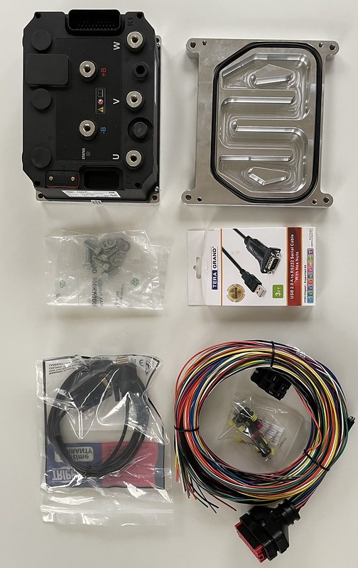
The contactor for precharging (slow power up for the controller to avoid big current spikes as the capacitors in the controller charge up) is missing as they sent the wrong one and I have sent it back for a replacement.
John has made the motor coupler - a little long so it can be trimmed to the correct length for the clutch mechanism. Seen below with the flywheel it bolts onto.

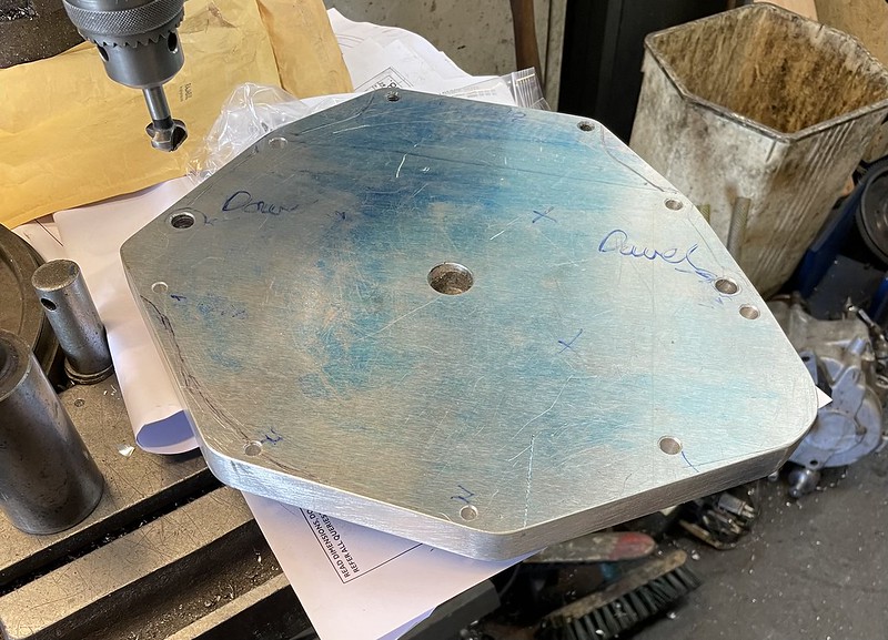
John has also made a start on the adapter plate
There was also a special offer at Burton and I have got an aluminium bellhousing as mine really was in an awful state, and at over 4kg lighter the ally one gives a nice weight saving.
I tapped that to fit the pivot bolt, and you can see the state of the original in the foreground.

I also did my first destructive act on the lotus and cut the redundant starter motor gear ring off the flywheel. I followed the workshop manual guide to cut a slot with a hacksaw then hammer it out with a metal chisel:
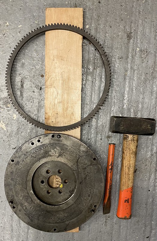
John will machine off the metal that the ring gear was pressed onto, to save some rotating mass.
I also got a Renault Hall effect sensor to act as the tachometer sensor. I will get a pair of holes drilled and tapped in the aluminium motor adaptor to take 2 bolts for the sensor to detect. And holes to mount it on the adapter plate. I will also get 2 slots cut for magnets if I find I need to use a less sensitive one to get it to work with the Spyder adapter I have for the Elan tachometer.
Back to other bits and pieces. So to the heater - my 2nd PTC heater module got lost in the post and the replacement will take another 45 days from China! So I took the case off to Curridge for blasting and coating and will drill and paint the holes now I have got it back. It will be nicer to work with once it is cleaned up!
So, as I had a batch for the powder coaters coming together, I decided to pull the old headlights apart. How many bits do you need for a headlamp?

The reflectors are clearly knackered and to save power I have bought some E marked LED modules. I took these down to my local MoT garage who confirmed that they are ok to pass the MoT. They fit nicely in place of my old sealed beam modules and they even use the old wiring connectors. I cleaned up the ring mount and treated the pitting with ku-rust.I am also short of one of the chrome headlamp finisher rings, and got one from eBay for £20.
I reassembled the steering column and found some fine bodgery. Whoever had the steering wheel off before, reassembled it with the cam which pushes the indicator off 180 degrees out of position.

Now corrected and self-cancelling now works. I am now wondering if I should swap the sides for the indicator and lights so it matches all my modern cars?
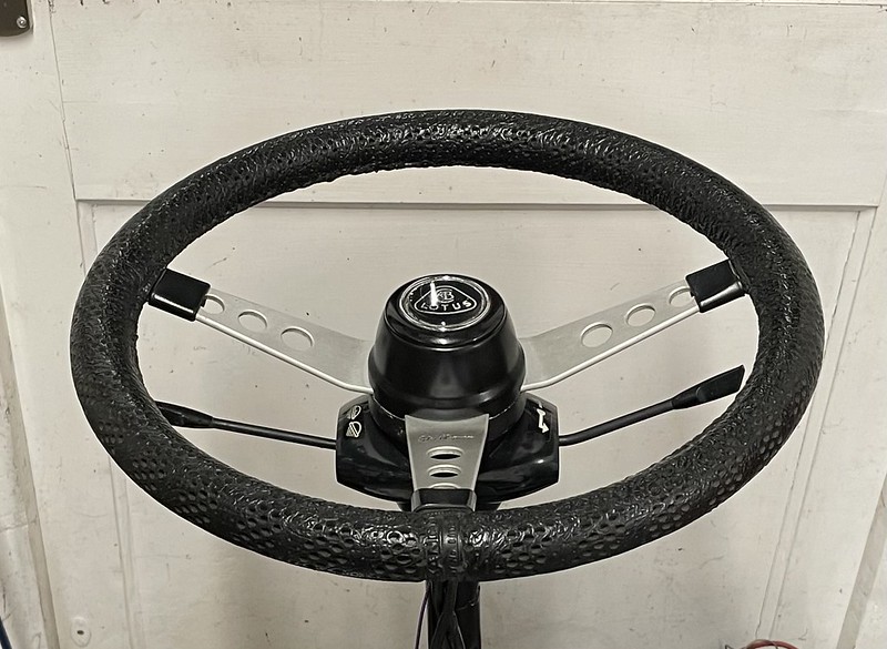
The steering wheel boss paint came up great (for me) and i am very happy with the finished assembly. I also ordered a pair of steering column bushes and will pop those in when they arrive.
Horn switch is now working correctly, but it’s a shame about the crazed horn push though.
I ordered a ¼ inch thread repair kit for the broken bolt in one of the window motor mountings, and of course when I got to it the broken screw just undid with a set of pliers.
Picked up the seats from Option 1 sports cars and they have done a lovely job!

The guys at Option 1 also recommended for the chassis body marriage that I make sure there is no underbody seal where the rear strut tower meets the body then to drop the body gently onto the chassis and allow it a day to settle then from underneath and then pack out any gaps between the body and chassis with stainless washers.
I had another look at my rear light clusters and they were pretty badly pitted:

Rechroming is quite expensive, so I thought I would have a crack at the ghetto approach and sanded, filled and primed them:

And applied 4 coats of Chrome paint:

To be honest, I am not very impressed (either with my filling skills or the chrome paint), but will see how they look on the car. Worst case I can paint them Gloss black like my Evora when chrome failed on its rear lights or perhaps try some Chrome wrap?
Current to do list:
They have done a fabulous job - I am very happy! The colour in the photos is a bit green tinged due to the fluorescent lighting, but in the sunlight it looks fabulous.
Looking at the rollover bar, Karl is much happier fitting it with the car on the chassis so I will arrange to ship it to Norfolk for the body chassis marriage and roll bar fitting once I have the motor in the chassis.
We also discussed the carbon fibre battery boxes and as Karl can make them for a better price and lighter than the American aluminium ones, I have asked him to go ahead and he will measure up once the body is back on the chassis. I have ordered and received the HV bulkhead connectors, battery bus-bars and coolant connectors for those too.
While I was ordering I also ordered the motor potentiometer which will connect directly to the Elans throttle cable and the DC-DC converter which will replace the alternator providing 14V from the main driver battery.
Also I ordered the 4 way connectors for the CAN bus - 3 of them as the can bus loops though one battery box through to the next.
On that note, I have given up with the Australian company for the motor adapter plate after months of missed promises and ignored emails. Last week I had a scaffolder around for some roof works and on spotting the Elan we got chatting about cars and his 1000hp Ford Popular drag car. He recommended John at PJO Engineering in Swindon who has made him adaptor plates to mate various V8s to all sorts of gearboxes, and after a quick visit and chat I have entrusted the work to him.
I ordered the motor so John can check measurements before he starts cutting metal and this has now arrived. John now has the motor drawings, the motor and my gearbox, bellhousing and clutch for measuring up and fabrication. It is great to work with someone who knows their stuff and has a real enthusiasm for it. He is also going to make up the motor mount for me as well!
I also have got the following bits together so John can measure up to make the adapter plate to go between the motor and the bell housing and a coupler which goes between the flywheel and the motor drive shaft:
Clutch housing - got
Clutch plate - got
Clutch release bearing - got
Bearing carrier - got
Release bearing spring fixings - got
6x bolt pressure plate to flywheel - got
6x bolt flywheel to adapter/engine - got
Release bearing D clip - got
Release arm “E” spring - got
Release arm boot - got
Privot bolt - ordered
Clutch Return spring - got
Clutch pilot bearing not - got
Gearbox to bellhousing bolts 7/16 N/C -got
Motor - got!
Here are some of the bits which come with the motor:
Wiring loom, USB cable for programming, power controller, chill plate, switch relay:
The contactor for precharging (slow power up for the controller to avoid big current spikes as the capacitors in the controller charge up) is missing as they sent the wrong one and I have sent it back for a replacement.
John has made the motor coupler - a little long so it can be trimmed to the correct length for the clutch mechanism. Seen below with the flywheel it bolts onto.
John has also made a start on the adapter plate
There was also a special offer at Burton and I have got an aluminium bellhousing as mine really was in an awful state, and at over 4kg lighter the ally one gives a nice weight saving.
I tapped that to fit the pivot bolt, and you can see the state of the original in the foreground.
I also did my first destructive act on the lotus and cut the redundant starter motor gear ring off the flywheel. I followed the workshop manual guide to cut a slot with a hacksaw then hammer it out with a metal chisel:
John will machine off the metal that the ring gear was pressed onto, to save some rotating mass.
I also got a Renault Hall effect sensor to act as the tachometer sensor. I will get a pair of holes drilled and tapped in the aluminium motor adaptor to take 2 bolts for the sensor to detect. And holes to mount it on the adapter plate. I will also get 2 slots cut for magnets if I find I need to use a less sensitive one to get it to work with the Spyder adapter I have for the Elan tachometer.
Back to other bits and pieces. So to the heater - my 2nd PTC heater module got lost in the post and the replacement will take another 45 days from China! So I took the case off to Curridge for blasting and coating and will drill and paint the holes now I have got it back. It will be nicer to work with once it is cleaned up!
So, as I had a batch for the powder coaters coming together, I decided to pull the old headlights apart. How many bits do you need for a headlamp?
The reflectors are clearly knackered and to save power I have bought some E marked LED modules. I took these down to my local MoT garage who confirmed that they are ok to pass the MoT. They fit nicely in place of my old sealed beam modules and they even use the old wiring connectors. I cleaned up the ring mount and treated the pitting with ku-rust.I am also short of one of the chrome headlamp finisher rings, and got one from eBay for £20.
I reassembled the steering column and found some fine bodgery. Whoever had the steering wheel off before, reassembled it with the cam which pushes the indicator off 180 degrees out of position.
Now corrected and self-cancelling now works. I am now wondering if I should swap the sides for the indicator and lights so it matches all my modern cars?
The steering wheel boss paint came up great (for me) and i am very happy with the finished assembly. I also ordered a pair of steering column bushes and will pop those in when they arrive.
Horn switch is now working correctly, but it’s a shame about the crazed horn push though.
I ordered a ¼ inch thread repair kit for the broken bolt in one of the window motor mountings, and of course when I got to it the broken screw just undid with a set of pliers.
Picked up the seats from Option 1 sports cars and they have done a lovely job!
The guys at Option 1 also recommended for the chassis body marriage that I make sure there is no underbody seal where the rear strut tower meets the body then to drop the body gently onto the chassis and allow it a day to settle then from underneath and then pack out any gaps between the body and chassis with stainless washers.
I had another look at my rear light clusters and they were pretty badly pitted:
Rechroming is quite expensive, so I thought I would have a crack at the ghetto approach and sanded, filled and primed them:
And applied 4 coats of Chrome paint:
To be honest, I am not very impressed (either with my filling skills or the chrome paint), but will see how they look on the car. Worst case I can paint them Gloss black like my Evora when chrome failed on its rear lights or perhaps try some Chrome wrap?
Current to do list:
- Refurb glovebox and fit fuse box and relays
- Get choke and heater knobs off and polished
- Build headlamp units
- Build up heater
- Do circuit diagram
- Fibre board trim
- Renovate badge
- Renovate hockey stick trim boards
- Order cable for High voltage and new 12V wiring
- Order batteries
- Order Charger
Excellent project OP.
You can get the chrome professionally painted with amazing results. I've seen it on Car Sos and Wheeler Dealers.
For example; https://www.chromefast.co.uk/
You can get the chrome professionally painted with amazing results. I've seen it on Car Sos and Wheeler Dealers.
For example; https://www.chromefast.co.uk/
Just read the thread from start to now....very impressive and some creative solutions to typical Lotus issues ...!!
I noticed that you have the original steering wheel, complete with the Colin Chapman signature...
IIRC I sold my signature wheel about 25 years ago for about £400 (!!) so goodness knows what they are worth now !
I replaced it with a thicker Moto Lita flat wheel, although I have seen Elans with a dished Moto Lita wheel.
I never liked the original steering wheel as they are so thin.
I also installed a differential strengthening bracket ( from Susan Miller IIRC ) that was standard on the later Sprint models. I see from your photos of the diff that there is quite a bit of wear on yours : I am guessing that with the EV motor you will have more torque going through the drivetrain...
You may even need a higher ratio diff with that extra power : my S4SE ( Strombergs ) always felt under geared, especially on longer trips ( I took mine to the Swiss Alps..) and I could understand why some owners changed over to a 5 speed box as the revs at motorway speeds are high.
Looking forward to your first 'silent' drive !
Cheers for the link Fore Left, I will get a quote!
Thanks Paul, the diff was well worn - to the extent I had to get a new rear casing for it. I do have the strengthening bar (the bit of right angle iron that sits on top of the diff?), it just does not appear in any of the photos. (I checked through all my photos, and even thought I thought I had photographed everything, I missed it out)
I fitted a 3.54:1 crown wheel & pinion which was the closest I could get to standard. I don’t think it will be too bad, the motor revs to 8k and being silent should not feet too wearing on longer trips. Once I get it going I will report on what it feels like for anyone else who might want to travel this road.
The steering wheel feels quite chunky with the perforated foam cover, not sure it that is standard or not!
I am aiming for late summer, but realistically it could take a while longer!
I am doing bits and pieces now while waiting for the motor adapter which is well under way, and the dashboard, which should be here in 10 days! It seems with classic cars everything takes ages!
I am doing bits and pieces now while waiting for the motor adapter which is well under way, and the dashboard, which should be here in 10 days! It seems with classic cars everything takes ages!
Edited by Spunagain on Monday 27th March 09:17

July 2023
It’s been a while!
Getting excited as the motor adapter should be here soon! I popped over to Swindon discuss the best place to mount the hall effect sensor for the Tachometer and saw the adapter plate and the coupler are done and have been bolted together to make sure it all fits. The flywheel has also been lightened:

Here is the adapter plate on my Hyper9 motor:


Next step is to remove the dowels from the flywheel and skim the face and then drill and tap 2 bolt holes onto the circumference to allow me to add 2 steel bolts for the Hall effect sensor to detect for the Tachometer signal. Finally to drill a hole in the bell housing to mount the Hall effect sensor onto. Hopefully that will be done this week and we can test fit the whole motor/gearbox assembly into the chassis and make up engine mounts next week.
A few small updates on my to do list:

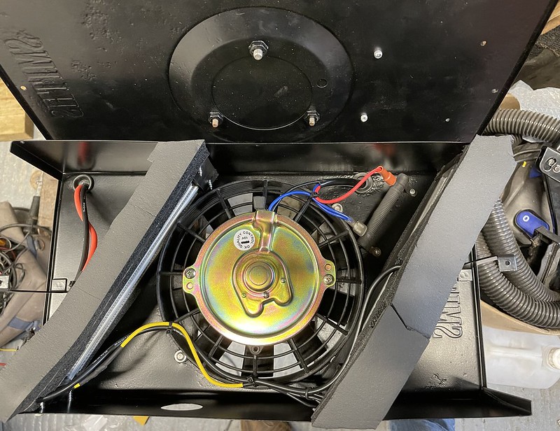
I was a bit worried about repositioning the dropper resistor as it was not in the direct airflow, but it worked fine. Here you can see the fan warming up using a thermal imaging camera

Here you can see a bit closer on one side

I was getting air coming out at 60°C on one side and a little cooler on the other. This was because the elements were not identical so one was dropping more volts than the other, this was fine as it created a worse case (hottest) condition and the max the hottest element got to was 102C (looking at the element using the thermal camera, and after 10 minutes the temperature held there.
I ran the heater for an hour with the flaps closed and cool air vent unblocked with slow fan speed to create the hottest case condition for the elements with slowest air flow through and all held steady and no smoke escaped!
I then stripped it down and checked for any evidence of heat damage but it all looked great so I rewired the elements in parallel ready for 120V supply and put it all back together again. Job done!

It is the box on the left - from left to right the connections are 240V AC in from the type 2 connector, CAN bus and DC voltage out to the battery pack. The box on the right is the DC-DC converter which is already in my pile of bits!
Now I have the batteries I can order it - which will be the last 4 figure expense!
As I am now not sure how long it will take so I did a very sketchy tidy up of the dash so I can use it if the other one is very late!
So I started with this:
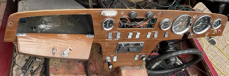
I took 3 stainless penny washers and drilled them to take the new switches for the seats and heater. I then milled out pockets for them in the old dash and glued them in. I then sanded the whole dashboard and filled the opened cracks in the veneer with superglue to give it a bit of strength and filled some dents and the ashtray screw holes. When this dried I sanded down again and wiped down with white spirit.
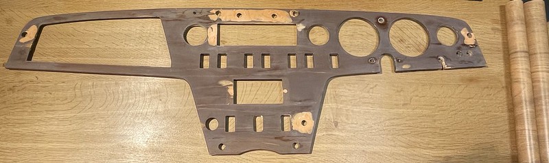
I then stuck on on some sticky back plastic oak veneer from amazon to tidy it up.

For the decals I had bought some ones I found on ebay when I had planned to refurb my own dashboard properly, but they just did not look right even for a temporary job.
The Elan decals are decals 3mm high and up to 45mm wide and use rare fonts called
10pt Microgramma bold extended https://freefontsfamily.com/microgramma-font-free/ and
12pt Eurostyle bold extended nebold https://freefontsvault.com/eurostile-font-family-f...
I printed some trial ones on paper and found Microgamma 14 point bold was the best fit.
I have found some white on clear Dymo D1 labels part no. 45020 on Amazon and borrowed a mate’s Dymo labeller as D1 cartridges don’t fit my household one. Also his one plugs into a USB port which allows me to use the Dymo PC application which allows me to select my own font.
Unfortunately after all that it seems to be limited to about 8 fonts only and did not pick up on my Microgramma font, so I took what I had and trimmed them to the outside edge of the text with a scalpel, and they look ok but would definitely get docked a few (more) concourse points! I have since found that you can take screenshots and paste them into the printer app so may update later but not worth the hassle for a temporary job.
The bezel for the battery display slotted straight into the ashtray hole without any mods and was glued in. I used the spare asymmetric bezel I had for this temporary dashboard.
I temporarily replaced the cigar lighter with a voltmeter so I can monitor the 12V battery during commissioning. For the final version I will replace this with the original Cigar lighter or pop in a USB charging socket.
I found the glove box brackets and refitted and have experimented with a block of 8 fuses and 4 relays in the glove box which will be for the side lights, auxiliary power and Fan blower high and low speed.
I drew up and then Andy printed me up a pair of 3d printed bushes (as mine are with the dashboard guy) and a bracket to mount my new LED friendly flashers onto the back of the dash.

So now looks presentable:


Now I can get on with some wiring! You can see all of the stuff now crammed behind the dash which I will wire to the Mate ‘n’ Lok connectors for easy maintenance.
I started drawing up the wiring diagram in Visio and quickly became overwhelmed, so to keep control I made up an Excel sheet with the following headings so I can keep track of the design schematic and the wiring up itself.
Still to do
It’s been a while!
Getting excited as the motor adapter should be here soon! I popped over to Swindon discuss the best place to mount the hall effect sensor for the Tachometer and saw the adapter plate and the coupler are done and have been bolted together to make sure it all fits. The flywheel has also been lightened:
Here is the adapter plate on my Hyper9 motor:
Next step is to remove the dowels from the flywheel and skim the face and then drill and tap 2 bolt holes onto the circumference to allow me to add 2 steel bolts for the Hall effect sensor to detect for the Tachometer signal. Finally to drill a hole in the bell housing to mount the Hall effect sensor onto. Hopefully that will be done this week and we can test fit the whole motor/gearbox assembly into the chassis and make up engine mounts next week.
A few small updates on my to do list:
- Order batteries
- Get choke and heater knobs off and polished
- Build headlamp units
- Build up heater
I was a bit worried about repositioning the dropper resistor as it was not in the direct airflow, but it worked fine. Here you can see the fan warming up using a thermal imaging camera
Here you can see a bit closer on one side
I was getting air coming out at 60°C on one side and a little cooler on the other. This was because the elements were not identical so one was dropping more volts than the other, this was fine as it created a worse case (hottest) condition and the max the hottest element got to was 102C (looking at the element using the thermal camera, and after 10 minutes the temperature held there.
I ran the heater for an hour with the flaps closed and cool air vent unblocked with slow fan speed to create the hottest case condition for the elements with slowest air flow through and all held steady and no smoke escaped!
I then stripped it down and checked for any evidence of heat damage but it all looked great so I rewired the elements in parallel ready for 120V supply and put it all back together again. Job done!
- Renovate badge
- Order Charger
It is the box on the left - from left to right the connections are 240V AC in from the type 2 connector, CAN bus and DC voltage out to the battery pack. The box on the right is the DC-DC converter which is already in my pile of bits!
Now I have the batteries I can order it - which will be the last 4 figure expense!
- Do circuit diagram
As I am now not sure how long it will take so I did a very sketchy tidy up of the dash so I can use it if the other one is very late!
So I started with this:
I took 3 stainless penny washers and drilled them to take the new switches for the seats and heater. I then milled out pockets for them in the old dash and glued them in. I then sanded the whole dashboard and filled the opened cracks in the veneer with superglue to give it a bit of strength and filled some dents and the ashtray screw holes. When this dried I sanded down again and wiped down with white spirit.
I then stuck on on some sticky back plastic oak veneer from amazon to tidy it up.
For the decals I had bought some ones I found on ebay when I had planned to refurb my own dashboard properly, but they just did not look right even for a temporary job.
The Elan decals are decals 3mm high and up to 45mm wide and use rare fonts called
10pt Microgramma bold extended https://freefontsfamily.com/microgramma-font-free/ and
12pt Eurostyle bold extended nebold https://freefontsvault.com/eurostile-font-family-f...
I printed some trial ones on paper and found Microgamma 14 point bold was the best fit.
I have found some white on clear Dymo D1 labels part no. 45020 on Amazon and borrowed a mate’s Dymo labeller as D1 cartridges don’t fit my household one. Also his one plugs into a USB port which allows me to use the Dymo PC application which allows me to select my own font.
Unfortunately after all that it seems to be limited to about 8 fonts only and did not pick up on my Microgramma font, so I took what I had and trimmed them to the outside edge of the text with a scalpel, and they look ok but would definitely get docked a few (more) concourse points! I have since found that you can take screenshots and paste them into the printer app so may update later but not worth the hassle for a temporary job.
The bezel for the battery display slotted straight into the ashtray hole without any mods and was glued in. I used the spare asymmetric bezel I had for this temporary dashboard.
I temporarily replaced the cigar lighter with a voltmeter so I can monitor the 12V battery during commissioning. For the final version I will replace this with the original Cigar lighter or pop in a USB charging socket.
I found the glove box brackets and refitted and have experimented with a block of 8 fuses and 4 relays in the glove box which will be for the side lights, auxiliary power and Fan blower high and low speed.
I drew up and then Andy printed me up a pair of 3d printed bushes (as mine are with the dashboard guy) and a bracket to mount my new LED friendly flashers onto the back of the dash.
So now looks presentable:
Now I can get on with some wiring! You can see all of the stuff now crammed behind the dash which I will wire to the Mate ‘n’ Lok connectors for easy maintenance.
I started drawing up the wiring diagram in Visio and quickly became overwhelmed, so to keep control I made up an Excel sheet with the following headings so I can keep track of the design schematic and the wiring up itself.
- Location
- Module (e.g. battery gauge)
- Pin - pin number or location of connector
- Wire base colour
- Wire trace colour
- Original Elan cable colour
- In Schematic?
- Wired up?
- Notes - e.g. where this pin is connected to
Still to do
- Fibre board rear firewall trim
- Renovate hockey stick sill trim boards
- Order charger, current probe, cable for High voltage wiring
- Label up the new chassis bolts for the body and chassis marriage
August 2023
The motor and gearbox is complete! Image from John:

Here you can see the Hall effect sensor and one of the bolts on the flywheel for it to pick up on. There are 2 bolts at 180° which give the same number of pulses per revolution as the distributor did. I will need to adjust the sensor mount so that the gap is between 1mm and 2mm.

John came over so we could drop the assembly into the chassis which was a bit of a struggle, but after lots of tipping and sawing the long bolt off the ball effect sensor mount we got it in place:

But there was a small problem. Once the gearbox was settled into its mount, it seemed the prop shaft was too long with the gearbox mounting set so it was as far forward as possible.
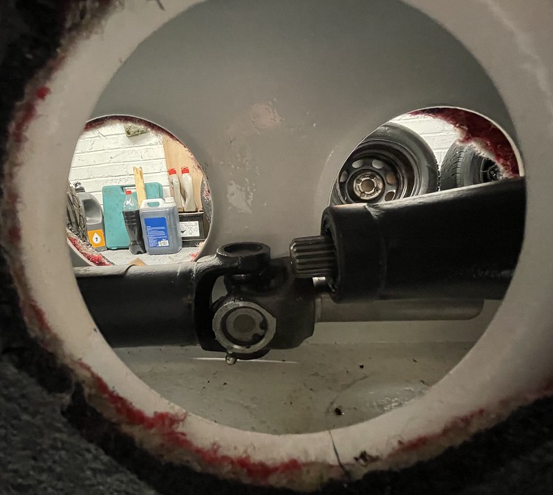
The prop shaft is 53.8cm from spring clip centre to spring clip centre - I checked with the Lotus experts to see if this is right and it is. It does seem that the new spline coupler has made it look a bit longer but the socket is actually deeper than it looks! It also turns out I slightly over-tightened the tie rods holding the diff in place which crushed the rubber bushes, drawing the diff closer to the gearbox. I loosened this a bit and the propshaft is now snugly in place.
John measured-up for the motor mounts and has drawn them up, and the metal arrived last week. Hoping to get everything in place this week!
I have simplified the cooling system to start with, and removed the battery heater loop and radiator bypass valves and will keep track of what the temperatures look like in the real world. This does mean I can’t charge or do regen if the ambient is below 0 degrees C.
The diagram below shows what I am planning. The numbers refer to a table of parts and hose inner diameters which allowed me to plan routing and parts ordering. Cooling loop:

Battery cooling for the 3 module box:
I then ordered pretty much all the missing parts on my shopping list:
Just need to get the miniature contact breakers to protect the charger, DC-DC converter, PTC Heaters and a big battery isolator switch.
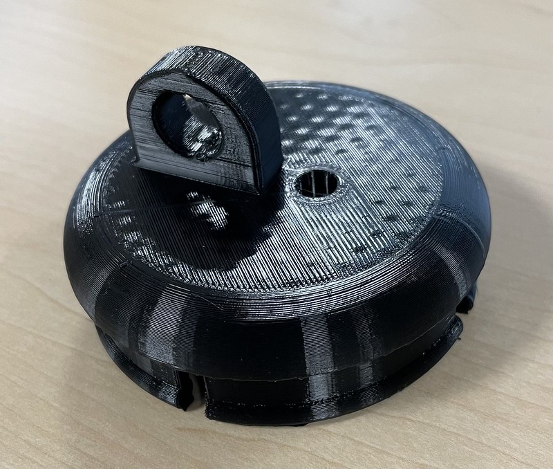
I also sketched up a cover for the starter motor hole which Andy kindly drew up and printed up:

First go was a little small and so we had a second go adding more lip and also not making it solid to save weight.
The motor and gearbox is complete! Image from John:
Here you can see the Hall effect sensor and one of the bolts on the flywheel for it to pick up on. There are 2 bolts at 180° which give the same number of pulses per revolution as the distributor did. I will need to adjust the sensor mount so that the gap is between 1mm and 2mm.
John came over so we could drop the assembly into the chassis which was a bit of a struggle, but after lots of tipping and sawing the long bolt off the ball effect sensor mount we got it in place:
But there was a small problem. Once the gearbox was settled into its mount, it seemed the prop shaft was too long with the gearbox mounting set so it was as far forward as possible.
The prop shaft is 53.8cm from spring clip centre to spring clip centre - I checked with the Lotus experts to see if this is right and it is. It does seem that the new spline coupler has made it look a bit longer but the socket is actually deeper than it looks! It also turns out I slightly over-tightened the tie rods holding the diff in place which crushed the rubber bushes, drawing the diff closer to the gearbox. I loosened this a bit and the propshaft is now snugly in place.
John measured-up for the motor mounts and has drawn them up, and the metal arrived last week. Hoping to get everything in place this week!
I have simplified the cooling system to start with, and removed the battery heater loop and radiator bypass valves and will keep track of what the temperatures look like in the real world. This does mean I can’t charge or do regen if the ambient is below 0 degrees C.
The diagram below shows what I am planning. The numbers refer to a table of parts and hose inner diameters which allowed me to plan routing and parts ordering. Cooling loop:
Battery cooling for the 3 module box:
I then ordered pretty much all the missing parts on my shopping list:
- 7kW Battery charger
- Bosch electric water pump
- HV cables
- Main HV fuse
- Coolant hoses and joiners
- Motorbike cooling fan for the repurposed Lotus oil cooler.
Just need to get the miniature contact breakers to protect the charger, DC-DC converter, PTC Heaters and a big battery isolator switch.
I also sketched up a cover for the starter motor hole which Andy kindly drew up and printed up:
First go was a little small and so we had a second go adding more lip and also not making it solid to save weight.

Fantastic Build record !! Well done !!
and thanks for sharing ..... wow what a brave man - a complete rebuild !!!
Mines been running well for 3 years about 6000m with zero issues.
However its a bit of a love/hate marmite car. I got cold the shoulder by several old skool Lotus folk
but welcomed by the newer guard.
Thanks for the heater info my winter project update (unless I bottle it and put in a domestic 120v US fan heater :-) )
cheers
Mark https://www.instagram.com/lotus_elon/
even accepted into autocar (who only grudging accept EV's right to exist :-) )
Well done on the progress so far.
As mentioned previously I owned an S4SE DHC for over 12 years, so I am familiar with a lot of the rebuild photos !
It still looks a bit strange seeing that electric motor in the engine bay ....!!!
I presume that as you will not have vacuum from the engine inlet manifold, you will have to get the pop up headlamp pods 'electrified'...
TBH the original vacuum reservoirs were a bit unreliable ...in fact I was stranded in The Lake District one very hot summer's day when the plastic T-piece cracked and lost all the 'power' ie vacuum for the headlight pods...on the UK models that meant the lamps stayed in the closed position.. which was no use when I had to drive 50 miles home at night...!
The US models had a 'fail safe' mechanism so the light pods stayed up.
My pal who has a couple of 'Baby' Elans converted the headlamp mechanism to an electric motor...IIRC Susan Millar had them...but it is a few years ago now.
Some people adapted the Mazda MX5 mk 1 system I seem to recall.
Anyway, great to see the amazing progress that you have made, and good to see that the project has been done to a high standard...!!
Looking forward to the first 'start up' if that is the correct EV expression !!
Hi Mark and Paul, thanks for the nice comments! It’s great to have someone out there to ask the Lotus specific questions! It is even better to know that the gearbox is surviving the torque!
No vacuum in the engine bay so I am going with the Spyder conversion which uses an MX5 motor https://www.spydercars.co.uk/electricy-headlamp-li... and have the kit safely tucked under the bed! I am wiring it so the headlamp pods pup up when the main/dip beam switch is turned on.
A US 12V fan heater may be a cheaper way to go for the electric heating but it will still need a 12V fan to drive it!
Some progress and a few detail bits:
Checked gearbox mount bolts and found and fitted the bolt fixing the gearbox to the bottom mount.
The engine mount was welded up by John and is good and chunky.
The 2 halves of the clam shells fit perfectly around the motor.
Unfortunately the lower half of the clamshell was too high at 46mm as there was only 24mm clearance between the motor and the chassis when the motor is level. John cut this down and re-welded 2 of the bracing triangles as I sawed them off to make more room for the Lotus engine mounts.
On the 2nd try everything fitted with 10mm clearance all round on the chassis.
I did give myself kittens by trying to roll the chassis in gear (1st) and found it locked solid but realised I was making life too hard for the drivetrain and when I dropped the gearbox it into 4th gear the whole drivetrain rotated freely!
Getting the chassis rolling with the whole drivetrain feels like a major milestone!

I adjusted the hall effect sensor clearance and made up a new lead soldered directly to the sensor as the connector did not allow enough clearance in the bell housing.

I measured starter bung depths for Andy to make up a new bung which is a bit more solid - the previous one was snug but not secure and added a screw hole to keep it in place:

I packaged up battery box parts for Karl and got the new body bolts ready for the body chassis marriage and topped off the gearbox to replace the load I dumped on the floor when dropping the motor and gearbox in.
For fun I worked on a template to emboss the Lotus logo on the battery boxes. Started with a photo of the old cam cover:

Used Paint (yes MS paint!) to edit a mono bmp file for the logo:

Andy converted that into an .sdf file using an on-line tool and created a 3d print 6mm high with a 0.5mm base which I sent photos of for Karl to review:

Turns you only need a very low feature height for it to show up in the carbon fibre and not create voids or bubbles, and in the past Karl has used vinyl stickers to get the effect, so we went for letters 0.5mm high and a lower profile 0.2mm base!

The very patient Karl is now picking up the chassis ready to drop the body on in about 2 weeks!
No vacuum in the engine bay so I am going with the Spyder conversion which uses an MX5 motor https://www.spydercars.co.uk/electricy-headlamp-li... and have the kit safely tucked under the bed! I am wiring it so the headlamp pods pup up when the main/dip beam switch is turned on.
A US 12V fan heater may be a cheaper way to go for the electric heating but it will still need a 12V fan to drive it!
Some progress and a few detail bits:
Checked gearbox mount bolts and found and fitted the bolt fixing the gearbox to the bottom mount.
The engine mount was welded up by John and is good and chunky.
The 2 halves of the clam shells fit perfectly around the motor.
Unfortunately the lower half of the clamshell was too high at 46mm as there was only 24mm clearance between the motor and the chassis when the motor is level. John cut this down and re-welded 2 of the bracing triangles as I sawed them off to make more room for the Lotus engine mounts.
On the 2nd try everything fitted with 10mm clearance all round on the chassis.
I did give myself kittens by trying to roll the chassis in gear (1st) and found it locked solid but realised I was making life too hard for the drivetrain and when I dropped the gearbox it into 4th gear the whole drivetrain rotated freely!
Getting the chassis rolling with the whole drivetrain feels like a major milestone!
I adjusted the hall effect sensor clearance and made up a new lead soldered directly to the sensor as the connector did not allow enough clearance in the bell housing.
I measured starter bung depths for Andy to make up a new bung which is a bit more solid - the previous one was snug but not secure and added a screw hole to keep it in place:
I packaged up battery box parts for Karl and got the new body bolts ready for the body chassis marriage and topped off the gearbox to replace the load I dumped on the floor when dropping the motor and gearbox in.
For fun I worked on a template to emboss the Lotus logo on the battery boxes. Started with a photo of the old cam cover:
Used Paint (yes MS paint!) to edit a mono bmp file for the logo:
Andy converted that into an .sdf file using an on-line tool and created a 3d print 6mm high with a 0.5mm base which I sent photos of for Karl to review:
Turns you only need a very low feature height for it to show up in the carbon fibre and not create voids or bubbles, and in the past Karl has used vinyl stickers to get the effect, so we went for letters 0.5mm high and a lower profile 0.2mm base!
The very patient Karl is now picking up the chassis ready to drop the body on in about 2 weeks!
January 2024
It’s been a while so a bit of an update: I sent the the completed rolling chassis off to Norfolk to join the body last month:

On Friday I drove up to Norfolk to see about mating the body and chassis and to talk through the battery box strategy. On the way I stopped off to visit Sue at Mick Miller Lotus and picked up cabin and boot carpet sets, a fibreglass rear trim piece for behind the seats and a new throttle cable.
I took up with me a kit of useful bits:
When I got to Phantom marine, Karl the boss and Gary who has done the bulk of the work, had started without me and I was greeted with this:


The body had dropped on very easily and Gary is working on fitting the roll over bar. He has removed the bracing on the sills to get it in rather than chopping a hole in the wheel arch and will refit in some newer bracing once it is all in.
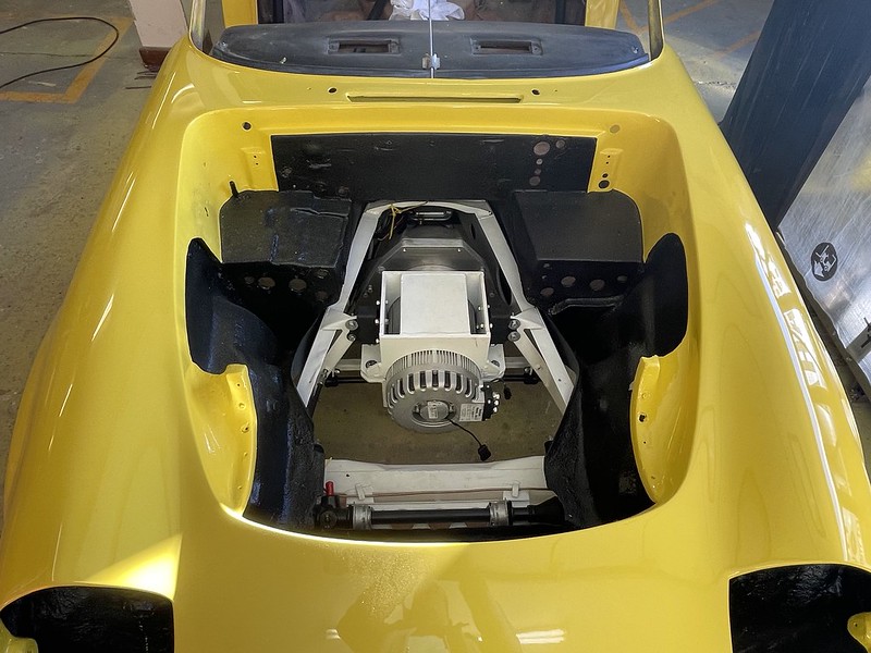
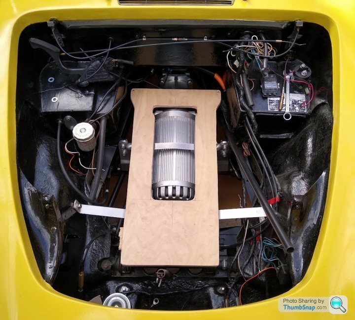
Once I had wiped the stupid grin off my face we started having a closer look at how we will do the battery boxed and immediately things were not going to go to my initial plan! Here is the engine bay:
I had suspected this may be an issue, the other Elan conversion bolted the motor straight to the gearbox with a narrow custom bell housing with no clutch and his motor mount is very low profile. My drivetrain keeps the clutch which makes the lowest point higher which means we can’t fit 3 batteries under the bonnet.
The new plan is to put 2 batteries under the bonnet and 3 in the boot. I will move the 12V battery, and DC to DC converter to the front to help compensate for the change. I may move the charger as well, but will think more about that when I can experiment with the real hardware in my garage.
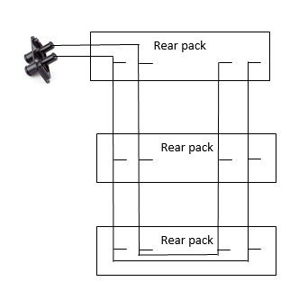
The connectors for the high voltage will be placed at the front of the engine bay pack, oriented so the connector has the cables coming out towards the back of the engine bay where the fuse and contactor box will live. I need to do some final measurements to see if the fusebox and motor controller can fit on the same side,if not the fusebox can go under the dashboard on the passenger side.. But the Motor controller must live on the passenger side ledge just in front of the firewall as that is the closest point to the three-phase connections on the motor.
The boxes will have mounting tabs on the bottom to allow them to be bolted down. Under the bonnet Gary will add a metal [ shaped mount which will attach to the strut tower chassis to body fittings just forward of the motor and will add a second more complex one attached to the engine mountings on the chassis.
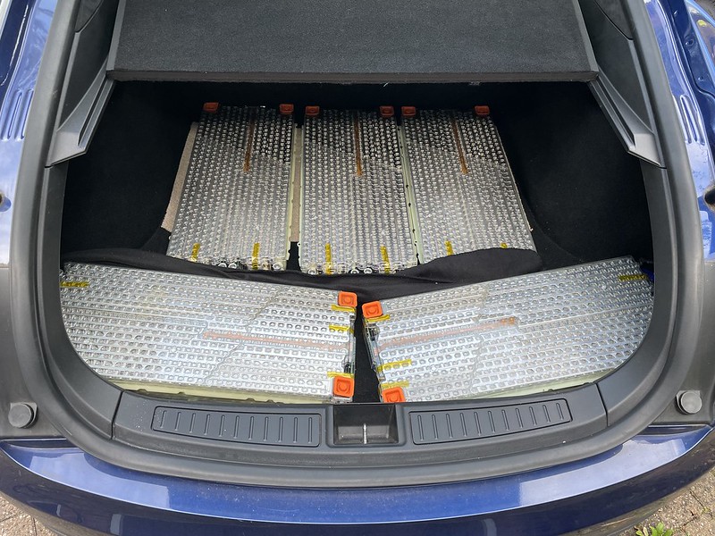
Here is an old picture of the boot:

The new plan is to cut out the hump in the left side of the boot where the exhaust used to be placed, to allow the larger battery pack to sit as low as possible. I will keep the fibreglass cut-out so it can be reinstated if needed. The cutout for the exhaust pipe under the bumper will not be removed though - I like the curves of it and may make up a fake tailpipe to sit in it!
The high voltage connectors will sit on the back facing side of the pack on the right hand side with the cables coming out towards the left of the car where they will come through the rear firewall and get routed through the sills, under the dashboard and routed out through the heater hose holes into the engine bay.
The coolant hose connectors will go on the back facing wall on the left side and get routed through the drivers side sill..
I might have avoided this if I had scanned everything in and drawn it up in CAD, but I do like a more iterative approach as it is very different to my real world job which comes to an end in March and I have April as gardening leave so plenty of time to work on the Elan. Karl has promised to get everything done well before then!
It’s been a while so a bit of an update: I sent the the completed rolling chassis off to Norfolk to join the body last month:
On Friday I drove up to Norfolk to see about mating the body and chassis and to talk through the battery box strategy. On the way I stopped off to visit Sue at Mick Miller Lotus and picked up cabin and boot carpet sets, a fibreglass rear trim piece for behind the seats and a new throttle cable.
I took up with me a kit of useful bits:
- 3 Tesla batteries
- Battery bus bars
- HV connectors
- The CAN bus connectors
- The coolant bulkhead connectors
- The Lotus logos for the top of the engine bay box
- A3 print of the Manual exploded diagram of the 16 bolts locations
- Labelled pack of new body bolts
When I got to Phantom marine, Karl the boss and Gary who has done the bulk of the work, had started without me and I was greeted with this:
The body had dropped on very easily and Gary is working on fitting the roll over bar. He has removed the bracing on the sills to get it in rather than chopping a hole in the wheel arch and will refit in some newer bracing once it is all in.
Once I had wiped the stupid grin off my face we started having a closer look at how we will do the battery boxed and immediately things were not going to go to my initial plan! Here is the engine bay:
I had suspected this may be an issue, the other Elan conversion bolted the motor straight to the gearbox with a narrow custom bell housing with no clutch and his motor mount is very low profile. My drivetrain keeps the clutch which makes the lowest point higher which means we can’t fit 3 batteries under the bonnet.
The new plan is to put 2 batteries under the bonnet and 3 in the boot. I will move the 12V battery, and DC to DC converter to the front to help compensate for the change. I may move the charger as well, but will think more about that when I can experiment with the real hardware in my garage.
The connectors for the high voltage will be placed at the front of the engine bay pack, oriented so the connector has the cables coming out towards the back of the engine bay where the fuse and contactor box will live. I need to do some final measurements to see if the fusebox and motor controller can fit on the same side,if not the fusebox can go under the dashboard on the passenger side.. But the Motor controller must live on the passenger side ledge just in front of the firewall as that is the closest point to the three-phase connections on the motor.
The boxes will have mounting tabs on the bottom to allow them to be bolted down. Under the bonnet Gary will add a metal [ shaped mount which will attach to the strut tower chassis to body fittings just forward of the motor and will add a second more complex one attached to the engine mountings on the chassis.
Here is an old picture of the boot:
The new plan is to cut out the hump in the left side of the boot where the exhaust used to be placed, to allow the larger battery pack to sit as low as possible. I will keep the fibreglass cut-out so it can be reinstated if needed. The cutout for the exhaust pipe under the bumper will not be removed though - I like the curves of it and may make up a fake tailpipe to sit in it!
The high voltage connectors will sit on the back facing side of the pack on the right hand side with the cables coming out towards the left of the car where they will come through the rear firewall and get routed through the sills, under the dashboard and routed out through the heater hose holes into the engine bay.
The coolant hose connectors will go on the back facing wall on the left side and get routed through the drivers side sill..
I might have avoided this if I had scanned everything in and drawn it up in CAD, but I do like a more iterative approach as it is very different to my real world job which comes to an end in March and I have April as gardening leave so plenty of time to work on the Elan. Karl has promised to get everything done well before then!
"I had suspected this may be an issue, the other Elan conversion bolted the motor straight to the gearbox with a narrow custom bell housing with no clutch and his motor mount is very low profile. My drivetrain keeps the clutch which makes the lowest point higher which means we can’t fit 3 batteries under the bonnet."
1st of all WELL DONE so far - I'm very impressed by your fastidious resto and careful build !
And are you sure 3 modules wont squeeze in there ??
Yes 3 modules and motor are VERY tight in the front .. and needed A LOT of compromises, all in the aim to match the original F to R balance.
1. No Clutch (means gear changes need to be be done with a 're-gen off' switch on the gearstick. 0-60 (on a full charge) suffers by about 0.5sec due to 2nd-3rd gearchange (second runs out of hyper9 torque so best is straight 3rd). I'd do the same again but maybe with a 3.9 diff ?? - luckily with the torque gear changes are not needed much.
2. The 3 modules had to stack super tight, and directly on each other - with special 3mm insulating foam between and tension / compression rods either side
3. There was no room for a metal battery box .. OK for UK but not if converted in EU. But petrol elans are not exactly fire proof - eg leaky carbs over dizzo, and TBH I like to see the packs - through a clear waterproof box.
4. The modules are jammed right upto to the firewall and there front top is 8mm below underside of bonnet.
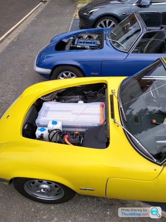
See next to Mates S4 which is within 20 serial numbers of mine. Cheers, Mark (the other :-) ) aka 'LotusElon' (trademark :-) ) https://mas-design.com/lotus-elon/https://www.instagram.com/lotus_elon/
1st of all WELL DONE so far - I'm very impressed by your fastidious resto and careful build !
And are you sure 3 modules wont squeeze in there ??
Yes 3 modules and motor are VERY tight in the front .. and needed A LOT of compromises, all in the aim to match the original F to R balance.
1. No Clutch (means gear changes need to be be done with a 're-gen off' switch on the gearstick. 0-60 (on a full charge) suffers by about 0.5sec due to 2nd-3rd gearchange (second runs out of hyper9 torque so best is straight 3rd). I'd do the same again but maybe with a 3.9 diff ?? - luckily with the torque gear changes are not needed much.
2. The 3 modules had to stack super tight, and directly on each other - with special 3mm insulating foam between and tension / compression rods either side
3. There was no room for a metal battery box .. OK for UK but not if converted in EU. But petrol elans are not exactly fire proof - eg leaky carbs over dizzo, and TBH I like to see the packs - through a clear waterproof box.
4. The modules are jammed right upto to the firewall and there front top is 8mm below underside of bonnet.
See next to Mates S4 which is within 20 serial numbers of mine. Cheers, Mark (the other :-) ) aka 'LotusElon' (trademark :-) ) https://mas-design.com/lotus-elon/https://www.instagram.com/lotus_elon/
Edited by Mark77a on Saturday 3rd February 19:09
Edited by Mark77a on Wednesday 7th February 15:12
Just looking at old build pix -- this is my battery undertray (before sealing) .. it fits directly on the top of the chassis where the chassis passes the bulkhead.
It was so tight it needed a cut out for the motor - but fitted. I think I can see similar space on your build.
It was so tight it needed a cut out for the motor - but fitted. I think I can see similar space on your build.
Edited by Mark77a on Wednesday 7th February 15:19
Hi Mark
Thanks for the encouragement!
The combination of the higher motor mount I have, and the larger bell housing means the 3 brick pack would need to move forward and would start fouling things at the front to fit.
I also need a little bit more clearance as my motor is on soft mounts as opposed to yours which looks like it is hard mounted to the chassis.
I think I can still get a pretty sensible F/R balance by moving as much to the front as possible.
Besides I can't be seen to copy you exactly
Gassing Station | Readers' Cars | Top of Page | What's New | My Stuff