500+bhp Mk3 Fiesta Project
Discussion


shalmaneser said:
two LSDs?
I am building two gearboxes for the car: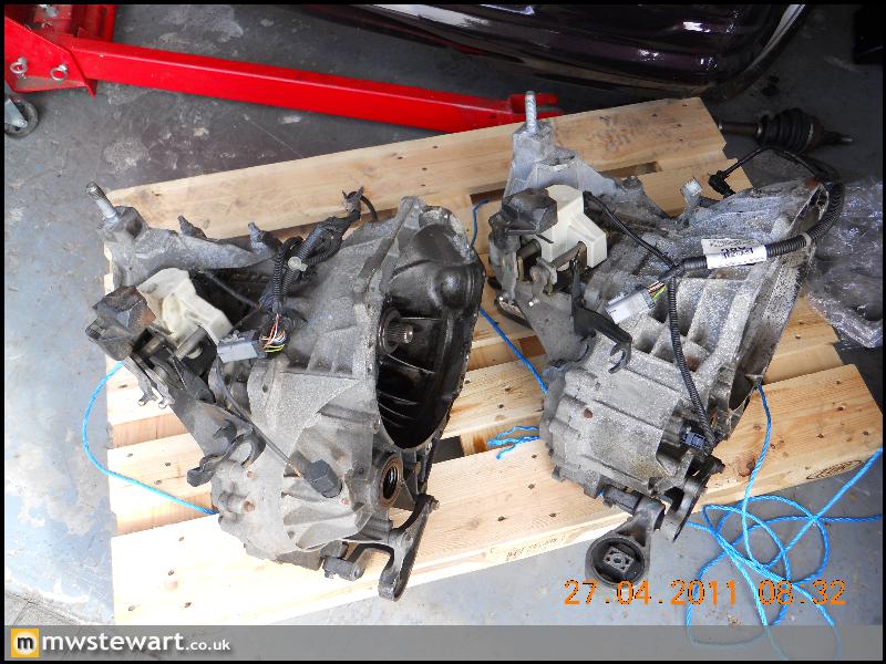
One will be a 'sprint' gearbox which will give me 180mph at 8500rpm, and the other is a more road biased gearbox with a taller final drive to allow 220MPH (theoretical) at 8500 rpm.
With the latter gearbox I aim to break the 190mph barrier.
5potTurbo said:
I may have missed it, but has anything been done on the engine front yet?
It's currently with my engine builder. It is a 2.0 Series 3/'Black top' Zetec engine as fitted to the Mk1 Focus. It was a brand new crate engine but will have the following modifications:Oversize valves;
Custom retainers;
Ported inlet and exhaust;
Double valve spring conversion;
Custom cams;
Forged pistons;
Custom forged rods (different rod ratio);
WRC Inconel manifold;
GT30 based custom spec turbo. Internal waste gate;
Pulsar inlet with single 65mm TB;
Pectel engine management.
The last engine on the engine dyno with this sort of spec made 522BHP at 8250RPM. The build will be finished in the next week or so.

warmfuzzies said:
Although it will have 522Bhp, and gearing to get to xxxmph, the CoD and frontal areas need to be taken into account to understand the final speed, do you have these specs in hand?
Its a pretty neat project, and I take my hat off to you sir.
K
Thank you very much.Its a pretty neat project, and I take my hat off to you sir.
K
I haven't been quite so scientific in that respect, at least yet. I'm basing the figure on the current top speed record for this mark of Fiesta which is 179.8mph along the 2.1 miles of Bruntinghorpe Airfield. Given I will have 100bhp more than that car, and will attempt the run over 3 miles, I am hopeful I will achieve the figure.
Having said that, I'm not building the car solely with that in mind; it'll be a bonus, nothing more.
Indestructible...I think that's optimistic 
Engine mounting today.
I bought the N/S section of a Focus inner wing to help me mount the gearbox, I also bought the O/S bracket for the engine mount. It turned out I didn't really need either
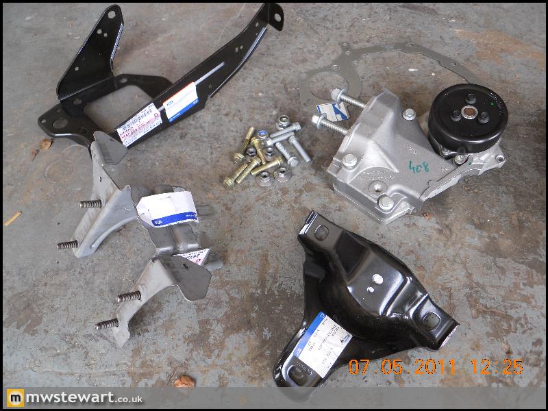
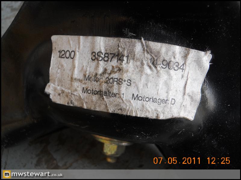
I am using Focus RS mounts. They are unique to that car and stronger than the rest of the range.
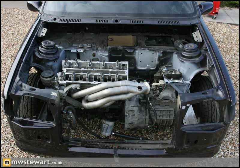
As the Black Top Zetec and MTX gearbox were never factory fitted to the Mk3 it is up to me to place the engine in the bay. This gives me a bit of flexibility in terms of engine height, but it's a careful trade off between a lower center of gravity and practicality for road use in terms of ground clearance. I settled on a final position that is just a fraction lower than the standard engine.
The old adage 'measure twice, cut once' saw me spend most of the afternoon with a tape and checking clearances everywhere, at one point I had the engine in a position where everything seemed to fit without the requirement for chassis modification, but it turned out to be too low. In the end I had to scallop a very small section from the N/.S chassis rail in order to make space for the gearbox.
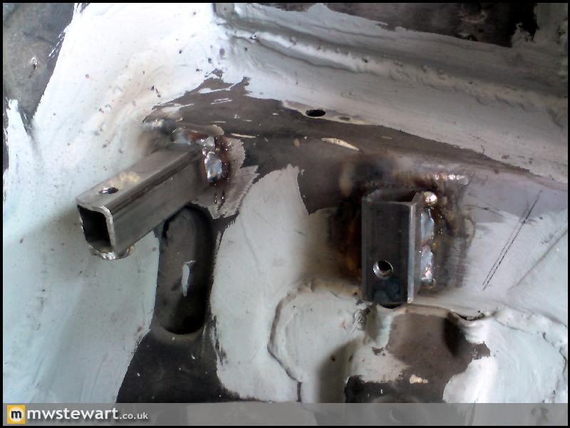
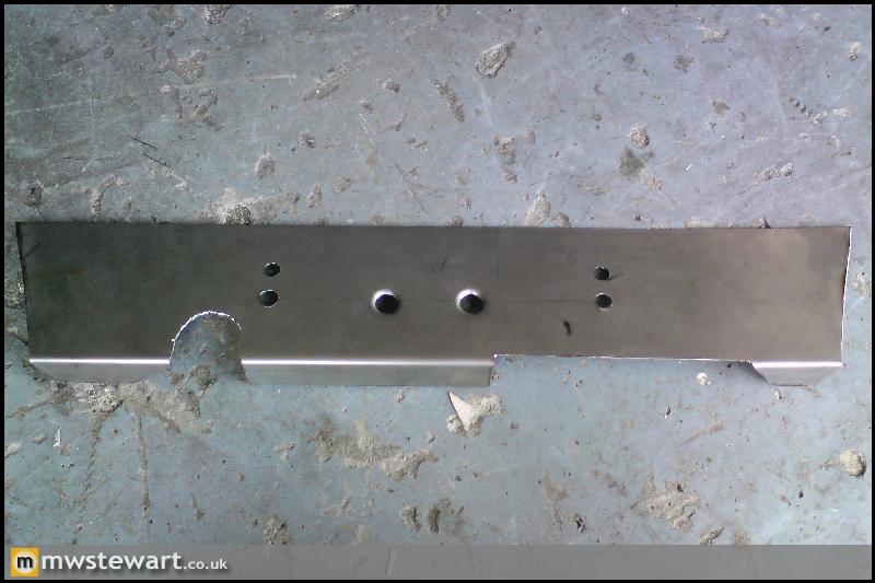
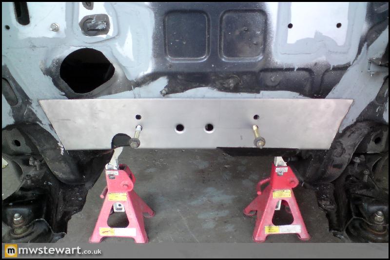
The fabrication for the engine mount was actually really straight forward:
Engine bolted in: It's at a funny angle because the gearbox end is suspended via the engine hoist.
Gearbox mount tomorrow.
Engine mounting today.
I bought the N/S section of a Focus inner wing to help me mount the gearbox, I also bought the O/S bracket for the engine mount. It turned out I didn't really need either
I am using Focus RS mounts. They are unique to that car and stronger than the rest of the range.
As the Black Top Zetec and MTX gearbox were never factory fitted to the Mk3 it is up to me to place the engine in the bay. This gives me a bit of flexibility in terms of engine height, but it's a careful trade off between a lower center of gravity and practicality for road use in terms of ground clearance. I settled on a final position that is just a fraction lower than the standard engine.
The old adage 'measure twice, cut once' saw me spend most of the afternoon with a tape and checking clearances everywhere, at one point I had the engine in a position where everything seemed to fit without the requirement for chassis modification, but it turned out to be too low. In the end I had to scallop a very small section from the N/.S chassis rail in order to make space for the gearbox.
The fabrication for the engine mount was actually really straight forward:
Engine bolted in: It's at a funny angle because the gearbox end is suspended via the engine hoist.
Gearbox mount tomorrow.
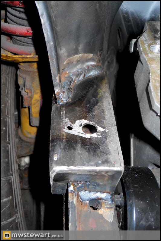
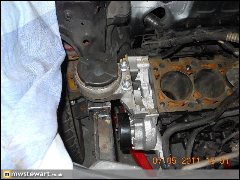
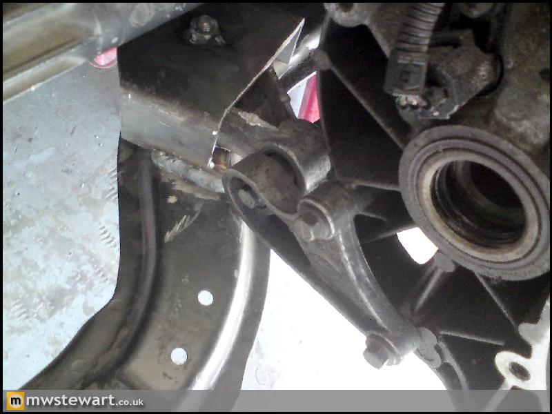
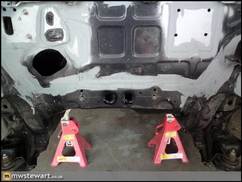
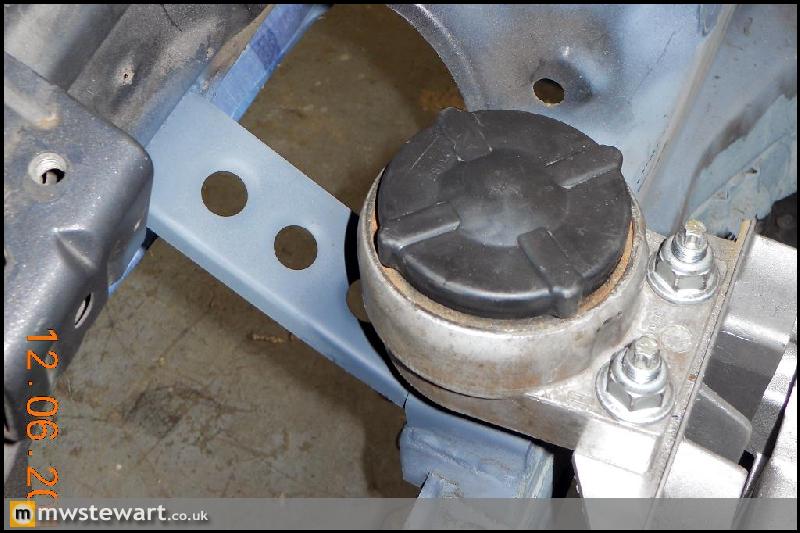
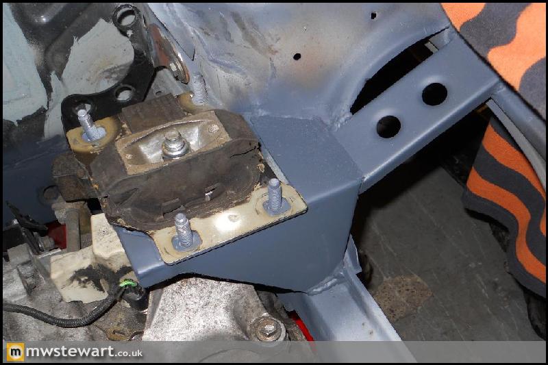
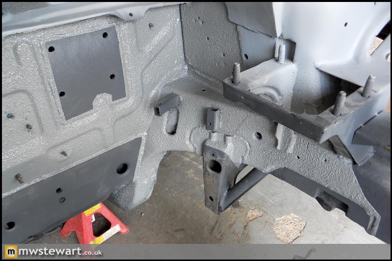
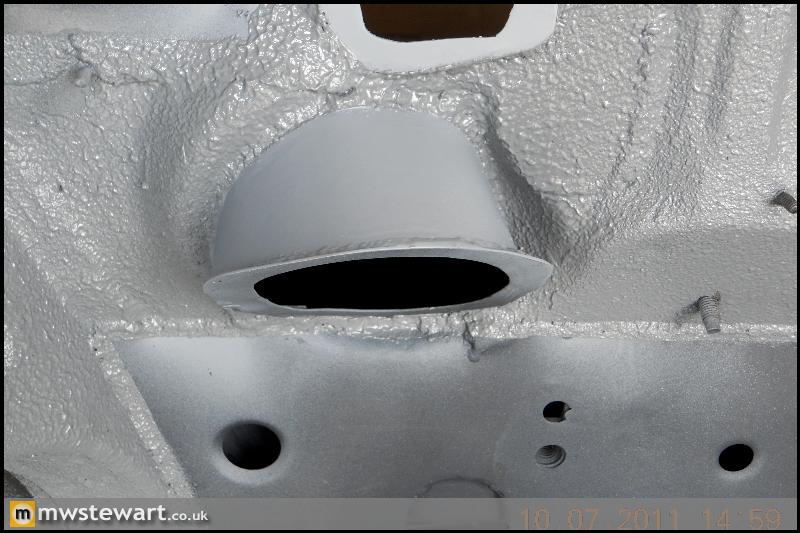
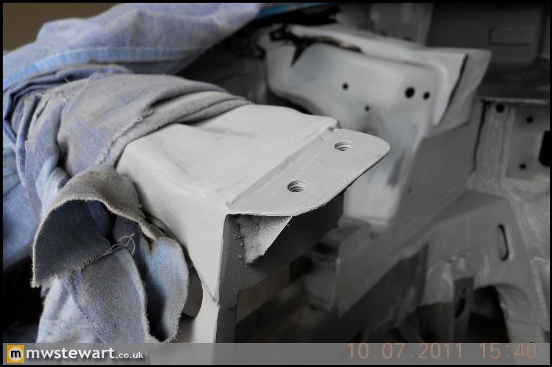
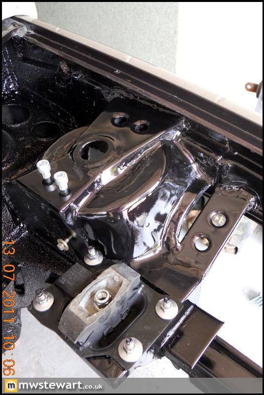
Chassis mounting point fabricated to suit the Focus engine mount. Since the last update I decided to raise this by 10mm in the interests of sump preservation, given that the car will be used on the road as well as track
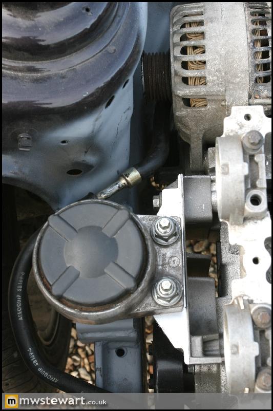
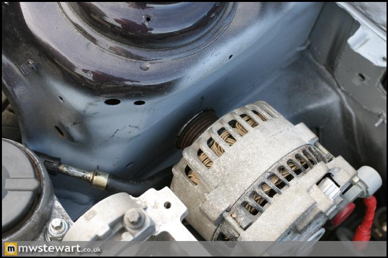
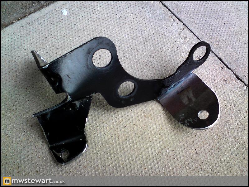
With the original Fiesta engine mount bracket removed there is sufficient room for the Focus alternator. The original bracket was welded to the area which is now covered in grey primer:
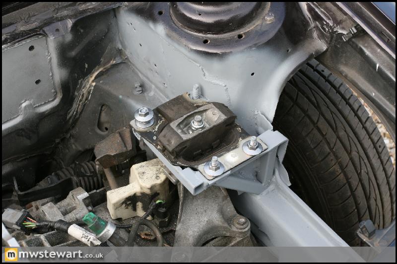
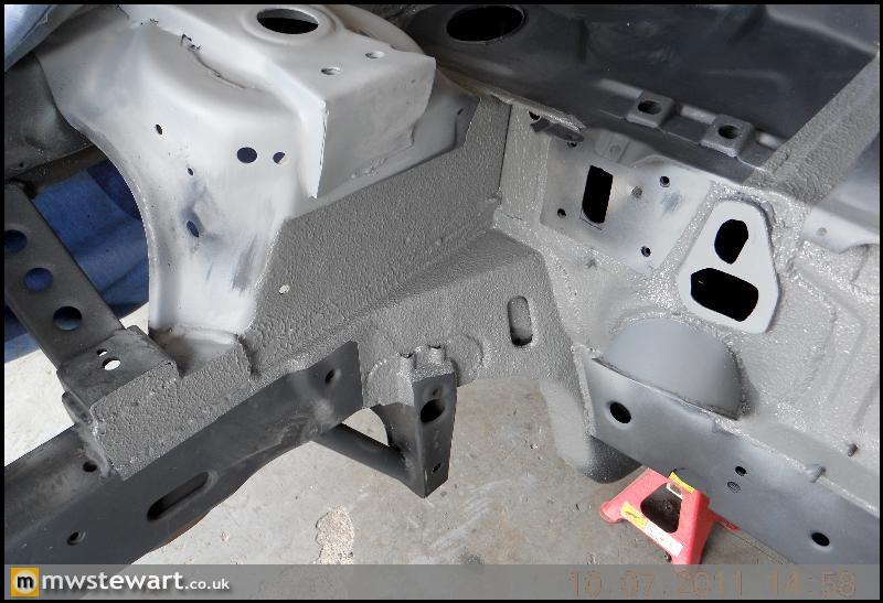
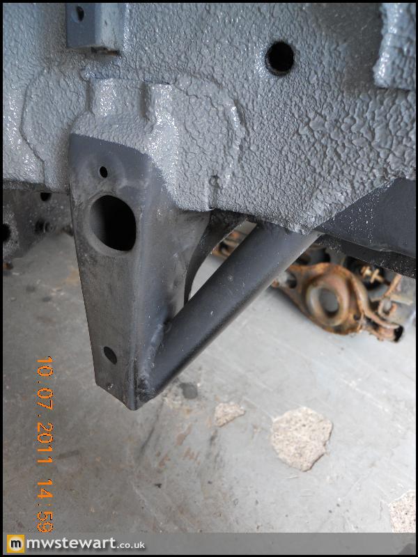
Focus gearbox top mount fabricated. The suspension turret had a protrusion half way down that took up valuable space, so I cut it out and plated over it; this let the new gearbox mount bracket sit flush with the turret. My aim was to modify the chassis to enable fitment of the standard Focus mounts, as this way they are easily replaced if anything breaks, and it also means the mount sits as far to the N/S as possible which leaves more room for the Turbo.
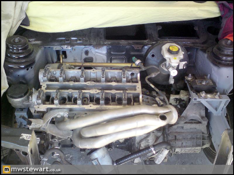
With ancillaries and manifold: all including the Air Conditioning compressor clear the chassis. The pictures show how the engine is tilted forward, which lowers the centre of Gravity. Tilting back is better but would mean major modifications to the bell housing.
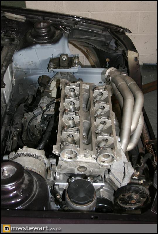
Now the structural areas of the mounts are in place I can next begin to make them look more OEM by plating over the gaps etc.
With the original Fiesta engine mount bracket removed there is sufficient room for the Focus alternator. The original bracket was welded to the area which is now covered in grey primer:
Focus gearbox top mount fabricated. The suspension turret had a protrusion half way down that took up valuable space, so I cut it out and plated over it; this let the new gearbox mount bracket sit flush with the turret. My aim was to modify the chassis to enable fitment of the standard Focus mounts, as this way they are easily replaced if anything breaks, and it also means the mount sits as far to the N/S as possible which leaves more room for the Turbo.
With ancillaries and manifold: all including the Air Conditioning compressor clear the chassis. The pictures show how the engine is tilted forward, which lowers the centre of Gravity. Tilting back is better but would mean major modifications to the bell housing.
Now the structural areas of the mounts are in place I can next begin to make them look more OEM by plating over the gaps etc.
Here are the outstanding fabrication/shell prep jobs:
- Make torque link bracket with a captive nut and mount on S Brace
- Mount brake link bar
- Modify brake servo brackets and mount Focus servo by welding on new tabs. Put a bend in the tabs so they go back to the bulkhead side and act as a reinforcement (leave space for the split pin hole)
- Fit ABS module
- Mark engine bay with Ancillary and gearbox locations including how much should be removed on the N/S leg to clear gearbox. Check for feasibility of leg gussets.
- Test fit O/S headlamp and check clearance for PAS pump
- Remove mock engine/gearbox
- Add cosmetic finishing to outside of Gearbox mount (add swages), include a bracket to mount positive terminal
- Fit front arch liners to check clearance around mounts, then remove
- Bridge Gearbox mount to inner wing
- Bridge Engine mount to inner wing
- Seam weld engine bay
- Add steering rack gussets
- Add two sub frame pick up points on each chassis leg
- Decide if ST hubs can be used and mount Mk5 turrets accordingly
- Reinforce turrets to chassis leg to lower arm mount
- Check clearances for use of Mondeo or Focus radiator
- Seam weld front wheel arch areas and apply primer
- Remove spare wheel carrier brackets and apply primer
- Fit rear arch liners
- Apply 3M Sealer to underside and rear arches
- Remove centre of front cross member: cut each side at an angle to help join of new CDS tube.
- Cap front cross member with flanges & captive fittings
- Make slam panel removable – add rivnuts and prepare edges.
- Mount Focus RS gear lever mech.
- Drill hole for AC drain.
- Seam seal rear turrets
- Paint engine bay, underside and boot area.
Thanks everyone. I work in IT Finance and I don't have any formal training in this stuff; I learn by reading and working on my own cars.
Another update, but please excuse the bad image quality as the photos were taken on an old phone.
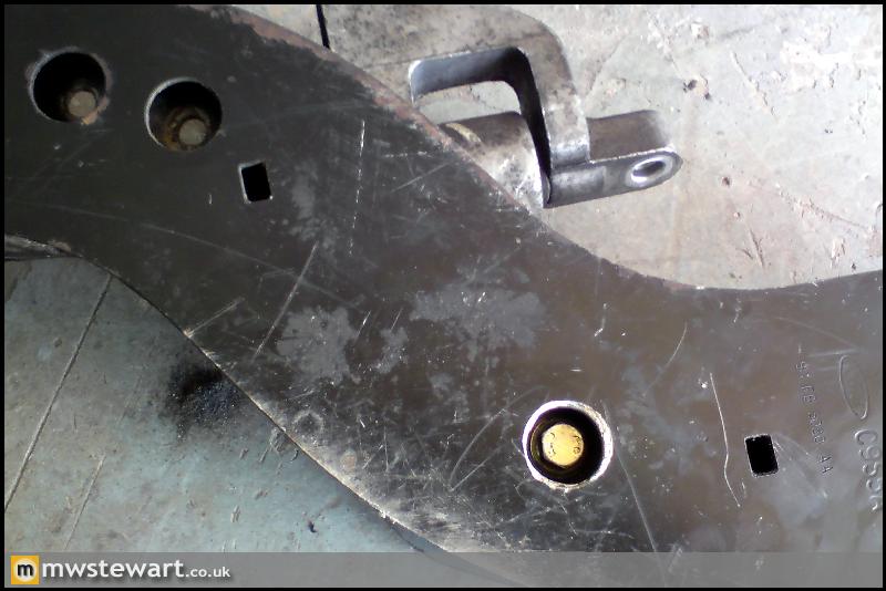
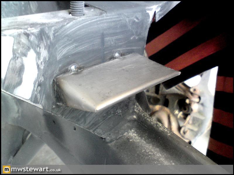
Fabrication of Gearbox Torque Link mount on to lower suspension 'S brace':
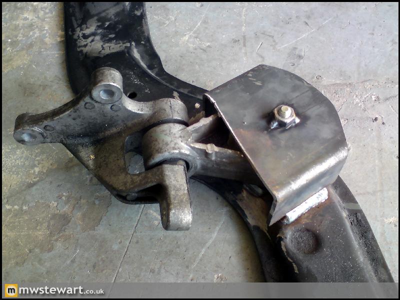
I drilled a 20mm hole in the outer skin so the bolt sits inside the brace, like Ford did with the ARB brackets to the left:
In position.
Mock up of the engine bay to allow me to check all clearances. I've now finished this stage and the mock engine has gone back to Ian (engine builder).
You may recall from my last update that I wasn't sure if the PAS pump would clear the O/S headlamp, well a trial fit conforms there is plenty of space.
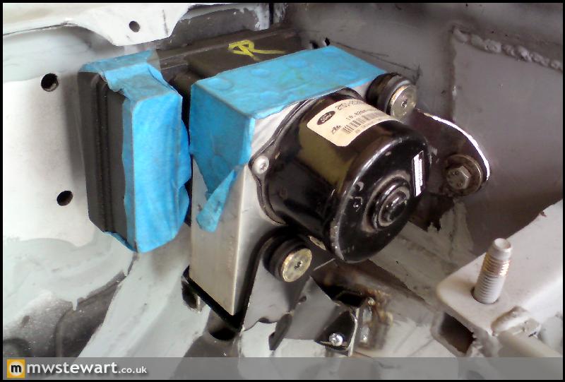
ABS/Traction Control Module mounting.
I bent/cut and welded a Focus bracket to suit my engine bay:
Some new lugs on the chassis leg:
Mounted:
Fitting of Puma Turrets.
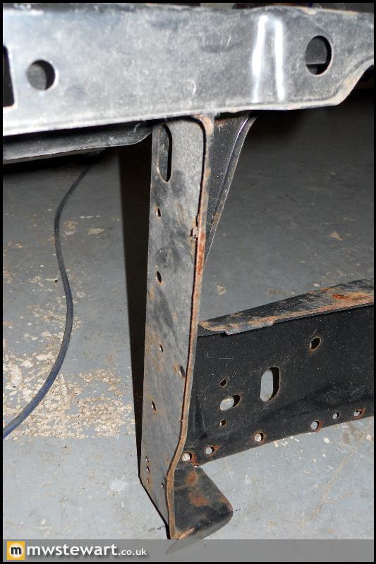
Standard Mk3 Fiesta turrets:
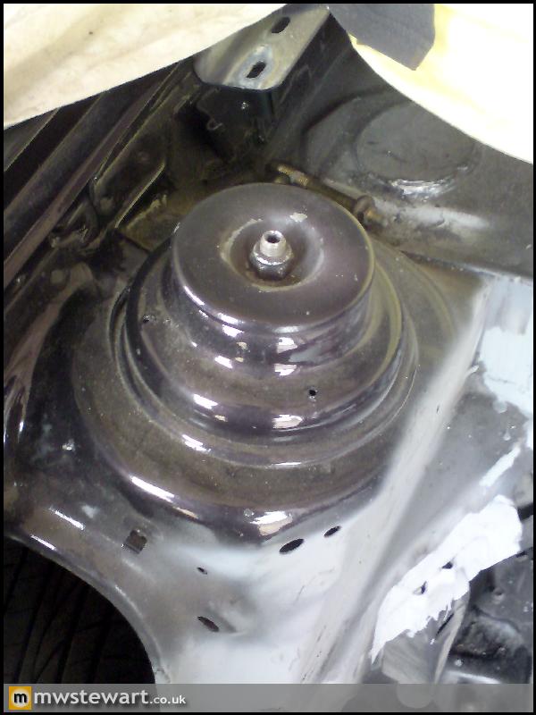
Removed:
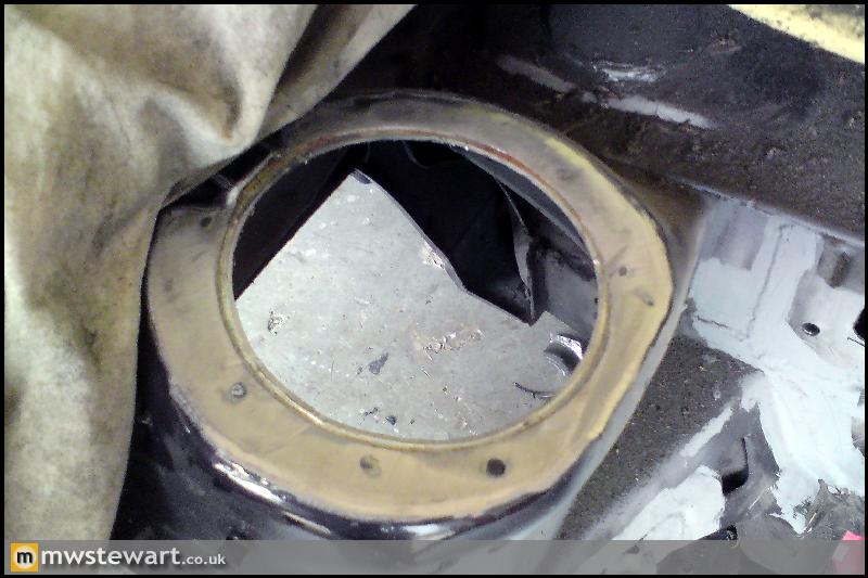
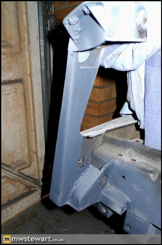
Puma turrets welded in place. These turrets open the door to a good range of performance suspension; I decided on a set of KW Variant 3 coil overs.
Finally some new Focus RS parts I bought for the engine build.
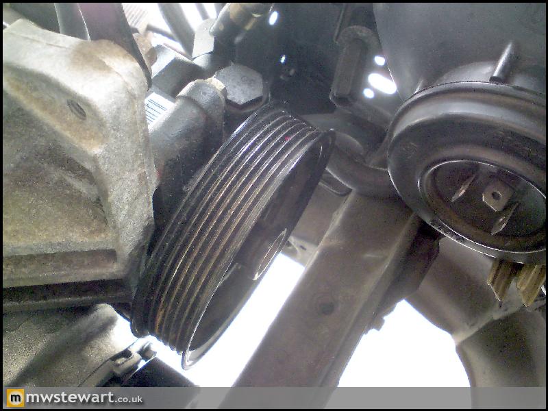
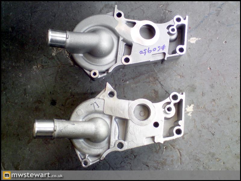
The Focus RS water pump flows 30% more than standard. While the standard water pump has been proven to 600bhp, I want to make sure I have the best components to ensure long term durability. The following photos show how large it is compared to the standard pump. Standard top, RS bottom:
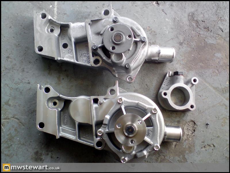
As the RS pump is so large I had to buy an RS specific pulley, Power steering mount and auxiliary belt tensioner. RS top, Standard bottom:
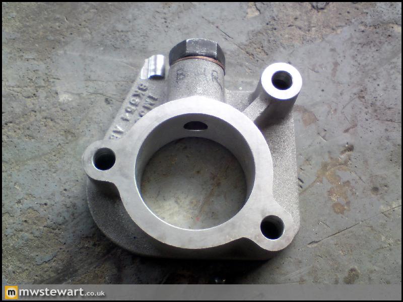
Focus RS thermostat housing spacer to provide a convinient take off for the Turbo water cooling feed.
I saw Ian yesterday and my bottom end is now built up. Ian says he will spend the new few days setting up the head. I've gone for the maximum size valves and a high lift cam and to accommodate this Ian ordered a set of custom cams with a different base circle, so that everything works in the head. Apparently there is a good few hours work in clearancing the valves for maximum efficiency.
Another update, but please excuse the bad image quality as the photos were taken on an old phone.
Fabrication of Gearbox Torque Link mount on to lower suspension 'S brace':
I drilled a 20mm hole in the outer skin so the bolt sits inside the brace, like Ford did with the ARB brackets to the left:
In position.
Mock up of the engine bay to allow me to check all clearances. I've now finished this stage and the mock engine has gone back to Ian (engine builder).
You may recall from my last update that I wasn't sure if the PAS pump would clear the O/S headlamp, well a trial fit conforms there is plenty of space.
ABS/Traction Control Module mounting.
I bent/cut and welded a Focus bracket to suit my engine bay:
Some new lugs on the chassis leg:
Mounted:
Fitting of Puma Turrets.
Standard Mk3 Fiesta turrets:
Removed:
Puma turrets welded in place. These turrets open the door to a good range of performance suspension; I decided on a set of KW Variant 3 coil overs.
Finally some new Focus RS parts I bought for the engine build.
The Focus RS water pump flows 30% more than standard. While the standard water pump has been proven to 600bhp, I want to make sure I have the best components to ensure long term durability. The following photos show how large it is compared to the standard pump. Standard top, RS bottom:
As the RS pump is so large I had to buy an RS specific pulley, Power steering mount and auxiliary belt tensioner. RS top, Standard bottom:
Focus RS thermostat housing spacer to provide a convinient take off for the Turbo water cooling feed.
I saw Ian yesterday and my bottom end is now built up. Ian says he will spend the new few days setting up the head. I've gone for the maximum size valves and a high lift cam and to accommodate this Ian ordered a set of custom cams with a different base circle, so that everything works in the head. Apparently there is a good few hours work in clearancing the valves for maximum efficiency.
Thank you. Anything is possible when you have a welder 
The S Brace was fitted to RS models and bolts between the lower arm mounting points, it's made from two pieces of 3.5mm steel so is perfect for the job.
You are correct, the original Fiesta gearbox mounts to a cradle that runs from the floor pan to the front cross member. This is now in the bin
The S Brace was fitted to RS models and bolts between the lower arm mounting points, it's made from two pieces of 3.5mm steel so is perfect for the job.
You are correct, the original Fiesta gearbox mounts to a cradle that runs from the floor pan to the front cross member. This is now in the bin
Ponk said:
Furry muff! I've been helping a friend fit a 2.1 ZVH (Zetec bottom end/CVH head) to his RS Turbo Fiesta. T3 or 4 turbo(can't remember) should be good for an easy 250bhp.
I'm guessing your ballpark is nearer 400-450?
I should imagine it’s a T3 as the T4 in any trim isn’t really suited to the Zetec. I’m not a big fan of the ZVH conversion as I would rather keep the 16v head. If the old CVH head is being kept for ease of installation then this can be achieved by fitting the CVH manifolds to the Zetec head by using adapter plates. It’s not an ideal solution but has been proven up to 350bhp. I'm guessing your ballpark is nearer 400-450?
My flywheel BHP will be a minimum of 500bhp, but I’m expecting closer to 550bhp knowing how Ian specs and quotes power figures.
Ponk said:
Hardly the same. With the Fords you can fit pretty much any engine to any gearbox to any car. You can't fit an XU engine (which i'm assuming you have nicked from a Xsara VTS?) or most BE gearboxes to an AX or 106. Plus there's simply not the same kind of engine choice as the Ford boys get.
This is a bit of a generalisation. There was a uniform bell housing bolt pattern used from the 70’s to mid 90’s, but this changed around 1995 and started to become engine specific (like mine). There does have to be an element of modularisation used by all manufacturers in order to keep costs down.My project here is the worst case scenario i.e. no original fixing points left in the bay, so it’s custom engine & gearbox mounts, and custom drive shafts. I could be fitting a 4cyl BMW engine for example, as there wouldn’t be any different or extra work involved.
You have the 2.0 Mi16 engine, don’t you? I gather that is very good. I’ve also seen the PSA V6 in a 205.
Greg_D said:
Where would one buy these adapter plates for bolting CVH stuff to zetec heads? it's just that my 2.1 zetec conversion has stalled a bit due to some muppetry from the engineering shop that has resulted in a scrap head, a new head is being sourced atm, but adapters would be ideal for me and save needing to get new studs fitted.
Hi Greg - don't tell me, exhaust studs to suit a CVH bolt pattern? I used this method in my first Zetec Turbo build but never again. I wouldn't recommend it to anyone.http://www.ferriday.co.uk/cnc/manifold.shtml


Parts update.
PAS Pump bracket and water pump pulleys, Focus RS (right) and standard (left). The FRS pump is driven at a higher crank ratio than the standard pump due to a smaller diameter pulley, and the PAS bracket is required to clear the larger FRS water pump body.

New Focus RS gear cables, 'lift up reverse' collar and short-shift gear mechanism.

Focus RS cam cover heat shield, oil breather heat shield, and water rail.

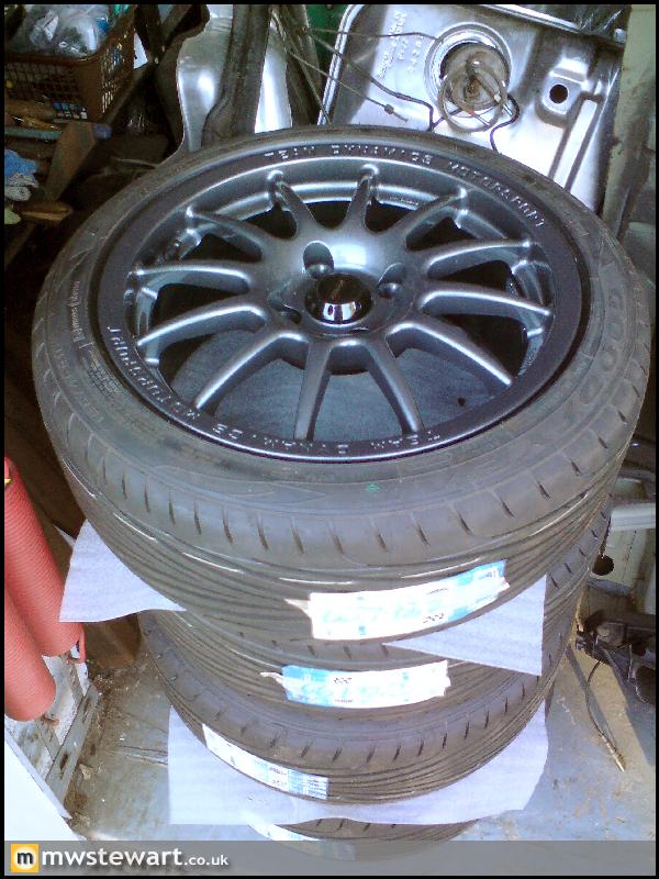
I also collected the new wheels. Tyre choice is Eagle F1 195/45/16

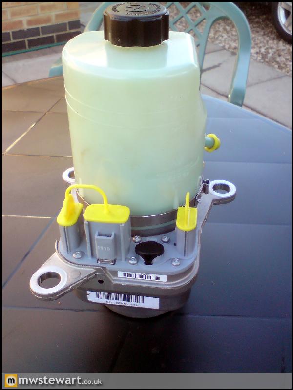
Even though the crank driven HPAS pump fits I have decided to use an EHPAS system, because I like the idea of a)reduced parasitic drag on the engine, and b) more weight shifted to the rear of the car. The pump will be mounted in the boot along with the dry sump tank, fuel system, and battery.
PAS Pump bracket and water pump pulleys, Focus RS (right) and standard (left). The FRS pump is driven at a higher crank ratio than the standard pump due to a smaller diameter pulley, and the PAS bracket is required to clear the larger FRS water pump body.
New Focus RS gear cables, 'lift up reverse' collar and short-shift gear mechanism.
Focus RS cam cover heat shield, oil breather heat shield, and water rail.
I also collected the new wheels. Tyre choice is Eagle F1 195/45/16
Even though the crank driven HPAS pump fits I have decided to use an EHPAS system, because I like the idea of a)reduced parasitic drag on the engine, and b) more weight shifted to the rear of the car. The pump will be mounted in the boot along with the dry sump tank, fuel system, and battery.
Max_Torque said:
If thats a TRW Gen 3 EHPAS unit, you'll have to hack the CAN to make it work properly..........
(luckily that's quite easy ;-)
(although with your FoMoCo contacts you might be able to russle up the CAN .db file for the car it came off, which would make things a lot easier)
Ahh, thank you. I checked the wiring diagrams before buying this and I found the following info on the Internet:(luckily that's quite easy ;-)
(although with your FoMoCo contacts you might be able to russle up the CAN .db file for the car it came off, which would make things a lot easier)
[*]The triple left side connector controls both the side aim headlamps, and ties in to steering limits for the ABS and ESP.
[*]The same goes for the low level triple power circuit on the right side.
[*]The centre is POWER earth and Live running a required boost of 14 volts, live only when the the engine is running. The left from the front is earth and right is live. They feed into a capacitor that stores high voltage in order to drive a high end winding that sits at the bottom of the unit in a ally dry case. Above this is a sealed oil is reservoir that is directly linked to the pump .
[*]The top and bottom are separate and the weakness in these pumps is that the motor locks at the lower bearing due to ingress of moisture .
My aim was to get this working with only +ve and neg, assuming that the level of assistance provided was fixed. I wanted to avoid the usual Saxo type pump as it looks a bit agriculutral and this Ford unit looks like a far better piece of engineering
I moved on from Dunton/Ford a few months ago now. Bearing in mind that I won't have CAN in the Fiesta can this pump be made to work?
Bespoke front cross member to increase room ahead of the engine so that I can fit a large Intercooler and radiator.
The standard front end with a cosmetic metal valance that is exposed on lower spec models.

Behind the valance is a box section cross member made from pressed 1mm sheet:

The Si has a deep front bumper and so the valance is superfluous. I removed the valance along with the original cross member:

Removed:


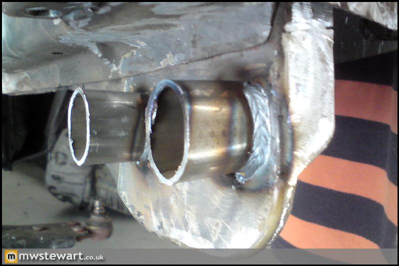
The material of choice for the new crossmember is 30mm diameter, 3mm wall CDS tube. The standard cross member is on the left, and the CDS on the right:

I had the CDS bent to my spec, and fabricated some brackets at each end along with matching brackets & captive fittings on the shell:

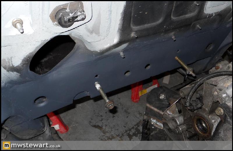
Bolted in (I'm not yet finished: there will be four more fixings added):


For added protection against grounding I let the new cross member sit 10mm below the bottom edge of the bumper.

The result is a great deal of space (in Fiesta terms) liberated at the front end, both in terms of depth and length. I can even trim 20mm from the rear face of the bumper and still the car would look standard from the outside.

The standard front end with a cosmetic metal valance that is exposed on lower spec models.
Behind the valance is a box section cross member made from pressed 1mm sheet:
The Si has a deep front bumper and so the valance is superfluous. I removed the valance along with the original cross member:
Removed:
The material of choice for the new crossmember is 30mm diameter, 3mm wall CDS tube. The standard cross member is on the left, and the CDS on the right:
I had the CDS bent to my spec, and fabricated some brackets at each end along with matching brackets & captive fittings on the shell:
Bolted in (I'm not yet finished: there will be four more fixings added):
For added protection against grounding I let the new cross member sit 10mm below the bottom edge of the bumper.
The result is a great deal of space (in Fiesta terms) liberated at the front end, both in terms of depth and length. I can even trim 20mm from the rear face of the bumper and still the car would look standard from the outside.
Max_Torque said:
You are right to avoid the "Saxo" type pump (actually a canadian HPI unit) as they have limited performance (approx 500W of hydraulic power) which isn't really enough in anything with a quick steering rack in it. I use the TRW pump in my rally car (from mk2 Focus RS) as it makes approx 1.2kW of hydraulic power and hence delivers significantly less "sag" when doing serious arm twirling (critical in my case because i have a high volume focus wrc rack (1.1turns LtL;-) )
The Gen3 TRW pump will need a CAN signal to run it unfortunately. (some people using the old Gen2 version say that it will run in a "limp" mode with just power connected (i.e. when it doesn't get any load signals off CAN, it defaults to running at a fixed meduim speed) My gen3 version does exactly nothing if you just power it........
I made a little controller that requests a pump speed based on vehicle speed, handwheel rate and a "mode" selector, giving me 3 choices for levels of assistance (i also implemented a "low battery" power down mode in case of alternator failure (the pump pulls well over 100A when fully loaded !!)

(note new alluminium end cap as pump is in the "cabin"

CAN controller
I am thinking about making the controller availible to people who want to use this pump for other applications such as yours.
Excellent, thanks for the info! So does the TRW unit take input from the steering sensor for the ESP? I assume it's a multifunction sensor that caters for rate as well as angle? My understanding is that speed sensitive PAS is something that has been bought in to drop the level of steering assistance at high road speeds, necessary because the rate of steering assistance has kept creeping up over the past years (because people want light steering when parking). I still prefer a fixed level of assistance; my rack is 2.4 LtL (1.1 must be nice!).The Gen3 TRW pump will need a CAN signal to run it unfortunately. (some people using the old Gen2 version say that it will run in a "limp" mode with just power connected (i.e. when it doesn't get any load signals off CAN, it defaults to running at a fixed meduim speed) My gen3 version does exactly nothing if you just power it........
I made a little controller that requests a pump speed based on vehicle speed, handwheel rate and a "mode" selector, giving me 3 choices for levels of assistance (i also implemented a "low battery" power down mode in case of alternator failure (the pump pulls well over 100A when fully loaded !!)
(note new alluminium end cap as pump is in the "cabin"
CAN controller
I am thinking about making the controller availible to people who want to use this pump for other applications such as yours.
Is the TRW pump run by a stepper motor, or is it a regular electric motor?
You have made a really nice installation in your rally car. I've been a bit slow off the mark getting to grips with CAN, I just haven't had the time. Good work!
Thanks guys - I definitely will get some video once it's all complete
Ponk - Thanks for the suggestion. I believe that the Corsa pumps are EPAS rather than EHPAS, and I want to avoid those systems because of the poor feedback.
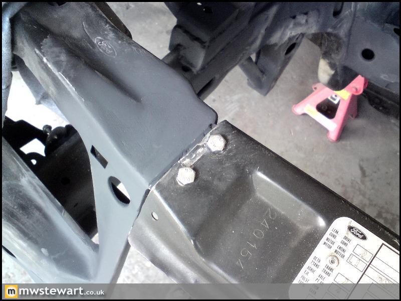
Today I finished off the mounting for the new cross member.
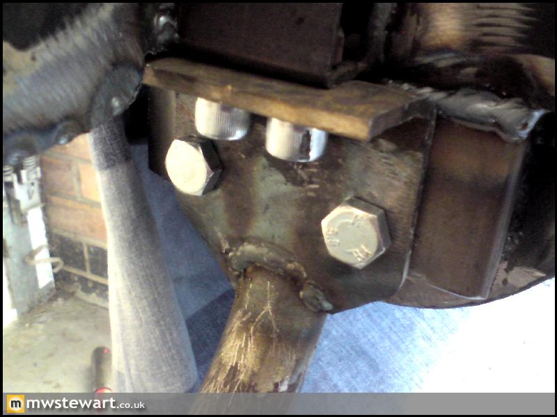
I wanted to bolt to some existing tabs that protrude down from the chassis legs, so I added some tube to prevent the tabs bending as the bolts are tightened:
I then boxed over them, drilled through, and welded a captive nut to the outside face of the tabs:
Next up is reinforcement of the steering rack mounting area to help further improve steering feel. The photo below is of the area in standard form, it's not particularly clear from the photo but the central 'pad' that the rack mounts to is isolated from the chassis rails either side of it:
The reinforcement piece I made which will link the rack mounts to the chassis rails:
And in place:
I ran out of time today so didn't get chance to weld it in. The above jobs look insignificant but take a fair amount of time.
Ponk - Thanks for the suggestion. I believe that the Corsa pumps are EPAS rather than EHPAS, and I want to avoid those systems because of the poor feedback.
Today I finished off the mounting for the new cross member.
I wanted to bolt to some existing tabs that protrude down from the chassis legs, so I added some tube to prevent the tabs bending as the bolts are tightened:
I then boxed over them, drilled through, and welded a captive nut to the outside face of the tabs:
Next up is reinforcement of the steering rack mounting area to help further improve steering feel. The photo below is of the area in standard form, it's not particularly clear from the photo but the central 'pad' that the rack mounts to is isolated from the chassis rails either side of it:
The reinforcement piece I made which will link the rack mounts to the chassis rails:
And in place:
I ran out of time today so didn't get chance to weld it in. The above jobs look insignificant but take a fair amount of time.
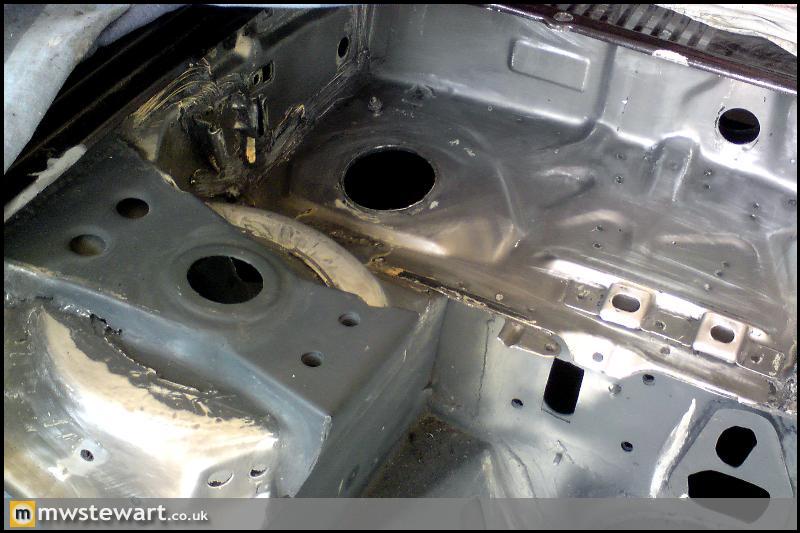
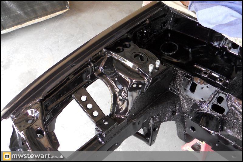
Engine mount bridged to inner wing:
Gearbox mount plated over and bridged to inner wing:
Steering rack reinforcement is on:
That's pretty much all the engine bay fabrication complete so now I can finally prep it for paint.
I also did some planning for the cooling system. I bought a Focus and Mondeo radiator pack to have a play around with, as these were the best fit for my engine bay.
Original radiator core: 500mm x 298mm x 27mm
Focus Mk1 core: 600mm x 358mm x 27mm
Mondeo Mk1 & Mk2 core: 620mm x 395mm x 27mm
I managed to get the Mondeo rad to fit however the outlet spigot is too close to the A/C pump. I have found a company who make uprated radiators for the Mondeo, so I have ordered an all aluminum rad with a 50mm core. I can then cut off the spigot and re weld in a slightly higher position.
Engine Bay Preparation
I stripped back to bare metal in key areas of the engine bay, to ensure a good finish.
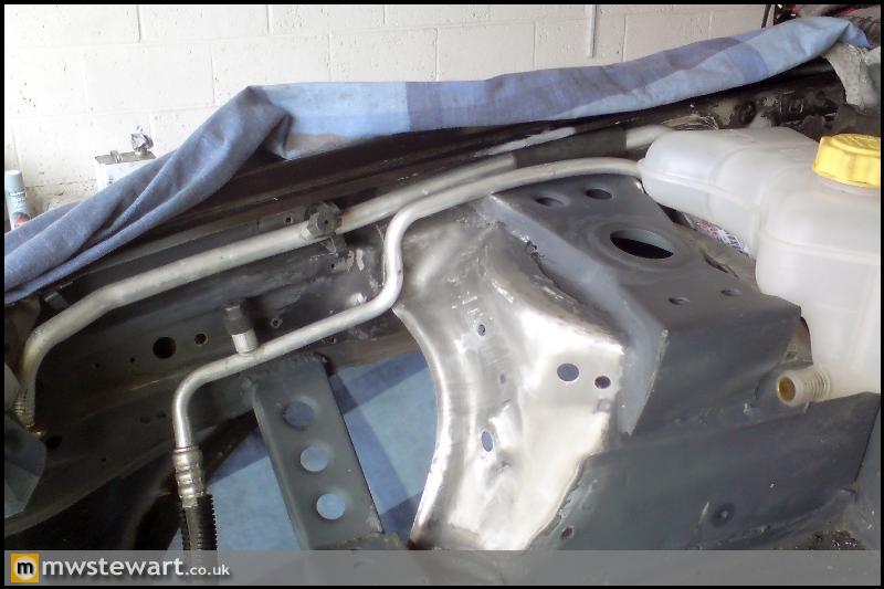
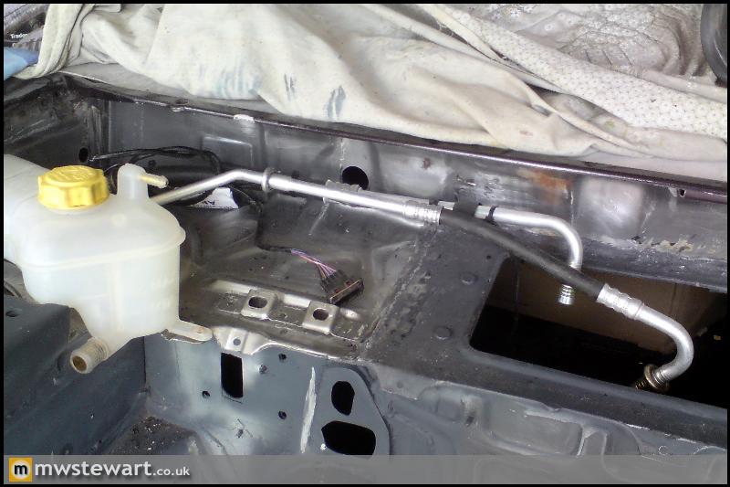
Air Conditioning Pipes - Test Fit
The AC pipes are from a Ford Puma which has an engine bay that is dimensionally very similar to the Mk3 Fiesta, so only a small amount of bending and reshaping was required. I've ordered some heat shrink to fit over areas which come close to the chassis.
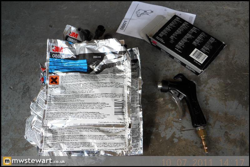
Sealer Application
3M 08800 is regarded as the best sealer available, it's not cheap but the quality and finish is superb - it's OEM for premium brands. A special applicator gun is required and is pictured below.
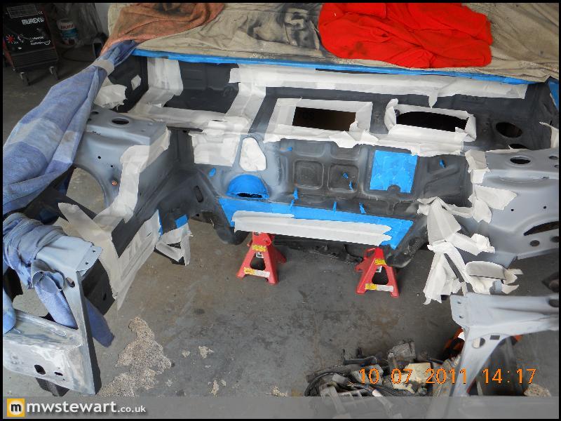
Engine bay masked off and 'panel wiped':
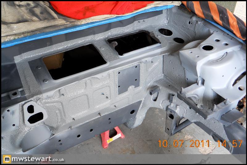
Sealed
Engine Bay Modifications
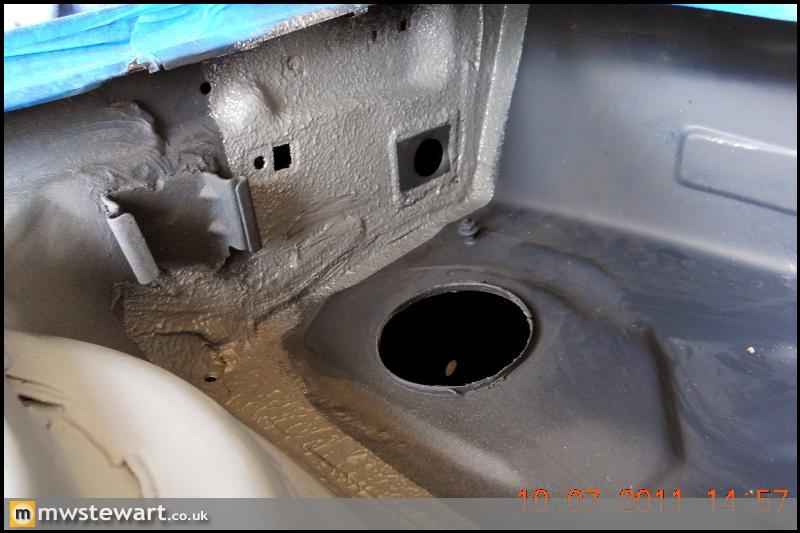
I'm relocating the screen wash reservoir to the rear of the O/S wheel arch in order to liberate space for the AC receiver. I added a swaged plate to the O/S inner wing so I can pass a filler tube through, I have Caravan black waste pipe in mind for this.
Bracket for a battery positive terminal. I'm relocating the battery to the boot so this terminal will let me join the existing positive wires to a 300 Amp cable that will run to the boot.
The original steering column was sealed on the bulkhead with a rubber grommet, and the UJ was still left exposed to the elements. The slight play in my UJ was testament to this. Taking inspiration from a later Fiesta I fabricated a shroud on the bulkhead which will enable me to mount a cover for the UJ.
Lower arm points reinforced to chassis leg
Slam panel clearanced for large radiator, and sectioned to be made removable in order to improve access to the radiators and engine. The first photo is of a standard panel for reference.
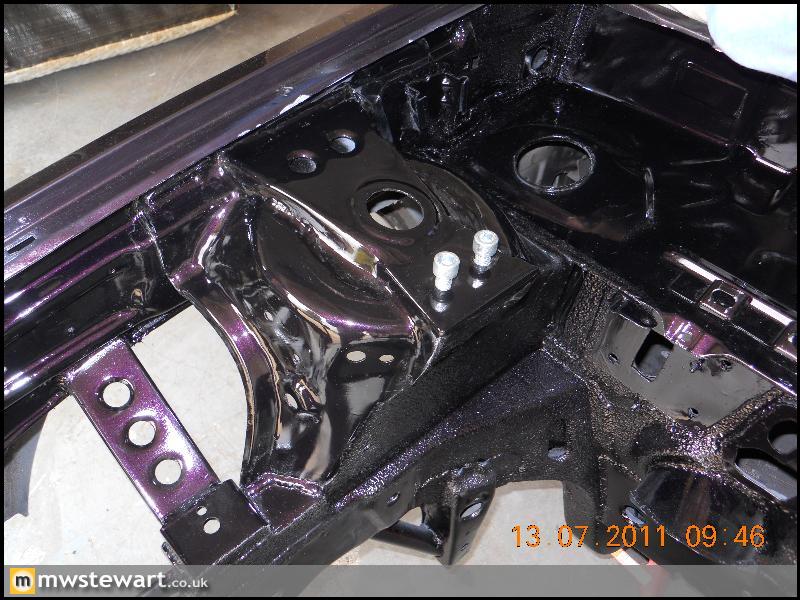
Painting
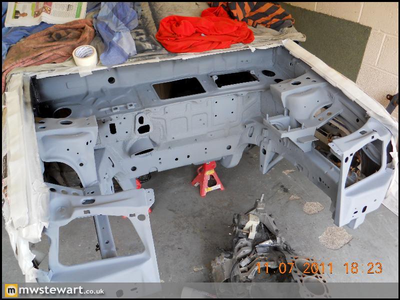
In primer
Painted
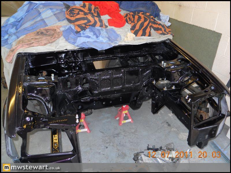
The rich colour really comes through in this shot:
Independent rear suspension
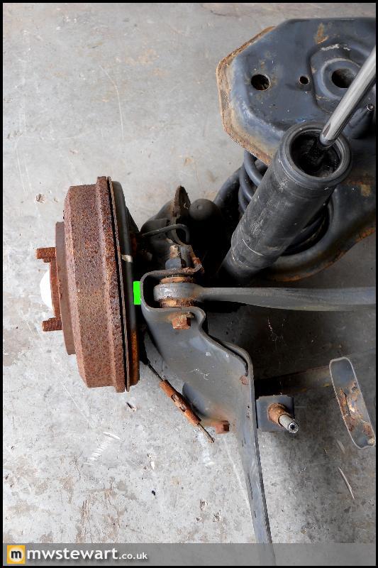
The next phase of the project is independent rear suspension taken from a Focus. I knew the Mk1 and Mk2 Focus shared an identical rear suspension arrangement aside from the hubs (5 bolt vs 4 bolt) so I bought a very low mileage rear beam/sub frame from a 2009 Focus. It turns out that the Mk2 hubs also have a significant track increase which meant I'd be running too much positive offset on the rear wheels when compared with my existing front axle. The green line in the photo below shows the distance between the lower arm and the hub mounting face:
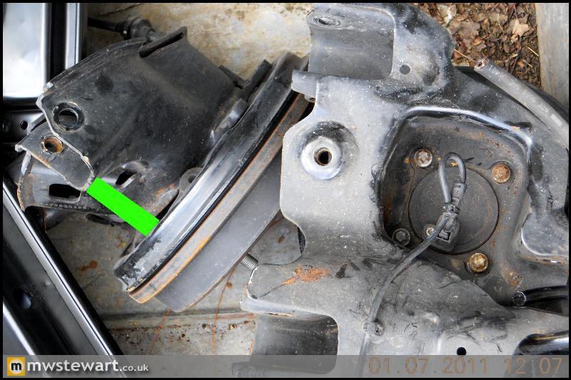
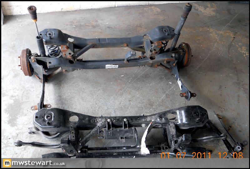
I bought another rear end, this time from a Mk1 Focus and the photo below shows the dramatic reduction in track width:
A comparison shot. I will use the newer Mk2 subframe and arms but with the Mk1 hubs and my own disc brake conversion.
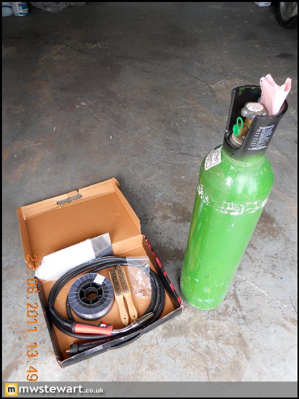
MIG Welding Aluminium
I wanted to break the dependence I had on local engineering firms for Alloy welding, so I bought some parts for my Mig Welder that will let me perform the job myself; pure Argon, Alloy wire (a general grade), oversize tips, Stainless Steel wire brushes and a Teflon lined torch.
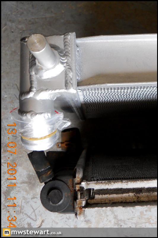
My first Alloy welding job will be to make some radiator brackets for my new radiator. It is an 'uprated' Mondeo radiator, all alloy and double capacity.
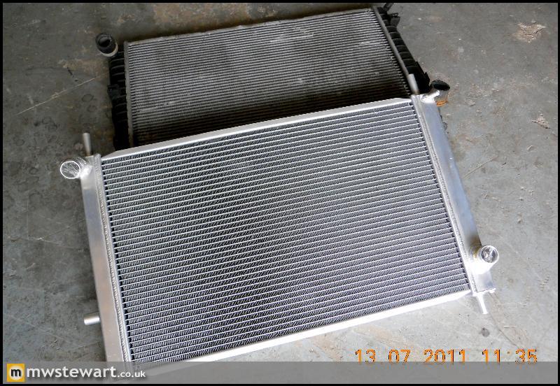
50mm vs 27mm core.
I stripped back to bare metal in key areas of the engine bay, to ensure a good finish.
Air Conditioning Pipes - Test Fit
The AC pipes are from a Ford Puma which has an engine bay that is dimensionally very similar to the Mk3 Fiesta, so only a small amount of bending and reshaping was required. I've ordered some heat shrink to fit over areas which come close to the chassis.
Sealer Application
3M 08800 is regarded as the best sealer available, it's not cheap but the quality and finish is superb - it's OEM for premium brands. A special applicator gun is required and is pictured below.
Engine bay masked off and 'panel wiped':
Sealed
Engine Bay Modifications
I'm relocating the screen wash reservoir to the rear of the O/S wheel arch in order to liberate space for the AC receiver. I added a swaged plate to the O/S inner wing so I can pass a filler tube through, I have Caravan black waste pipe in mind for this.
Bracket for a battery positive terminal. I'm relocating the battery to the boot so this terminal will let me join the existing positive wires to a 300 Amp cable that will run to the boot.
The original steering column was sealed on the bulkhead with a rubber grommet, and the UJ was still left exposed to the elements. The slight play in my UJ was testament to this. Taking inspiration from a later Fiesta I fabricated a shroud on the bulkhead which will enable me to mount a cover for the UJ.
Lower arm points reinforced to chassis leg
Slam panel clearanced for large radiator, and sectioned to be made removable in order to improve access to the radiators and engine. The first photo is of a standard panel for reference.
Painting
In primer
Painted
The rich colour really comes through in this shot:
Independent rear suspension
The next phase of the project is independent rear suspension taken from a Focus. I knew the Mk1 and Mk2 Focus shared an identical rear suspension arrangement aside from the hubs (5 bolt vs 4 bolt) so I bought a very low mileage rear beam/sub frame from a 2009 Focus. It turns out that the Mk2 hubs also have a significant track increase which meant I'd be running too much positive offset on the rear wheels when compared with my existing front axle. The green line in the photo below shows the distance between the lower arm and the hub mounting face:
I bought another rear end, this time from a Mk1 Focus and the photo below shows the dramatic reduction in track width:
A comparison shot. I will use the newer Mk2 subframe and arms but with the Mk1 hubs and my own disc brake conversion.
MIG Welding Aluminium
I wanted to break the dependence I had on local engineering firms for Alloy welding, so I bought some parts for my Mig Welder that will let me perform the job myself; pure Argon, Alloy wire (a general grade), oversize tips, Stainless Steel wire brushes and a Teflon lined torch.
My first Alloy welding job will be to make some radiator brackets for my new radiator. It is an 'uprated' Mondeo radiator, all alloy and double capacity.
50mm vs 27mm core.
Thanks guys!
Andy - You are absolutely correct! The MTX75 is what I'm using. Ford recently sold off all of their Focus RS Mk1 parts stock so I took the opportunity to pick up a couple of Quaife ATB's (they were very cheap) and a Focus RS Gearbox, which has the Quaife ready fitted together with shot peened gears.
Is the 6 speed the MMT6? which was fitted to the Mk3 Mondeo and later? I know there's also a Getrag MT285 which was fitted to the Focus ST170, but I don't think that's rated as highly as even the MTX.
Very good to know that your friends are putting 500 through the MTX; I knew it was a pretty sturdy box. It should be even better for me as I won't have any where near the level of the grip your Noble has.
Gassing Station | Readers' Cars | Top of Page | What's New | My Stuff