Diagram for the HVAC control knobs
Discussion


I've seen the diagram for the HVAC control module, and it doesn't appear to show anything for the control switch panel. Looking at pictures, the switches appear to be connected to the module, via a ribbon. I can only presume that's the reason for a lack of diagram ?
Does anybody know what each pin is doing, please ?
I'm guessing minimum of 12v+, 0v-, cold fan position, hot fan position, AC request, Rear screen request, AC acknowledge for the Blue LED, Rear screen acknowledge for the Red LED.....
So at least 8 pins (8 way ribbon) ?
I suppose the timer for the Heated screen could be built in to the switch pcb, so maybe at least 7 pins.
Edit... just found a picture, and they've used a 10 way ribbon. Presuming they're all utilised, each fan knob could use Two wires.
Hopefully one of you kind people, will have done the hard work for me
Edited by RUSSELLM on Tuesday 25th April 10:47
Finally got round to having a look at this today
Might come in handy for anyone using the search facility.
I can’t quite work out how the HVAC control knobs are held into the dash, so i’ve took these readings from the controller in the footwell, whilst plugged in at both ends....
This is a ‘sort’ of working system, but my cold and hot fans aren’t reaching full speed.
Pin 1 sends 4V for the Blue Air Con LED
Pin 2 is an electronic ground, when you turn the hot blower on, it changes to 1.5v variable to 2.3v as you twist the hot knob
Pin 3 is 5V
Pin 4 is an electronic ground, when you turn the cold blower on, it changes to 1.5v variable to 2.4v as you twist the cold knob
Pin 5 is 5V
Pin 6 is an electronic ground that goes to 5V when you turn the cold blower on
Pin 7 appears to be a hard ground.
Pin 8 sends 2v for the Red heated screen LED
Pin 9 is an electronic ground that goes to 5V when you turn the hot blower on
Pin 10 is 5V
......
That I thought, leaves pins 3,5 and 10 doing nothing. However, I suspect 3 or 10 is the supply for the control knobs pcb. As I found that pin 5 shorts to pin 6 as and when you press the heated rear screen button, in theory 5 is the demand wire.
I then suspect 3 or 10 is the command for the air con, but like you reading this, I was losing the will to live
My cold blower motor/fan is only getting a maximum of 9.6v to it, so lacks a bit of power. I suspect my hot fan is suffering the same. I think that pin 4 of mine, that only gives me a maximum of 2.4v, is the problem. As when I bridge it to 5V, I then get 12v at the cold fan. I reckon those potentiometers should vary from 1.5 to 5V.
HTH someone
There are some potentiometers on the control panel pcb which can be adjusted to increase fan speed. I've also been advised by a TVR electronics guru that the maximum fan speed available is 93% as the control box uses pwm with a max duty cycle of 93%. I've used an arduino to measure the voltage across the cold fan knob vr and at the appropriate point switch a relay connecting the fans directly to ground, bypassing the control box, to give 100% so Ive got the best possible cooling on european road trips.
Cheers.
At the actual fans, I can see a permanent 12v+ there and the control box controls the ground. I threw a good ground straight at the fan and got maximum voltage, so I could always stick a switch there, but ideally i’d like the control knobs to do it properly.
That 1.5v to 2.4v coming out of the cold knob, gives me 3v to 9.6v at the fan. I’d like to think the 3v is probably correct as it’s a nice gentle blow.
The adjustable potentiometers... are they at the knobs or in the control box ?
CerbWill said:
There are some potentiometers on the control panel pcb which can be adjusted to increase fan speed. I've also been advised by a TVR electronics guru that the maximum fan speed available is 93% as the control box uses pwm with a max duty cycle of 93%. I've used an arduino to measure the voltage across the cold fan knob vr and at the appropriate point switch a relay connecting the fans directly to ground, bypassing the control box, to give 100% so Ive got the best possible cooling on european road trips.
RUSSELLM said:
Cheers.
At the actual fans, I can see a permanent 12v+ there and the control box controls the ground. I threw a good ground straight at the fan and got maximum voltage, so I could always stick a switch there, but ideally i’d like the control knobs to do it properly.
That 1.5v to 2.4v coming out of the cold knob, gives me 3v to 9.6v at the fan. I’d like to think the 3v is probably correct as it’s a nice gentle blow.
The adjustable potentiometers... are they at the knobs or in the control box ?
HUM. additional cooling for when abroad/in hot weather... sounds interesting...At the actual fans, I can see a permanent 12v+ there and the control box controls the ground. I threw a good ground straight at the fan and got maximum voltage, so I could always stick a switch there, but ideally i’d like the control knobs to do it properly.
That 1.5v to 2.4v coming out of the cold knob, gives me 3v to 9.6v at the fan. I’d like to think the 3v is probably correct as it’s a nice gentle blow.
The adjustable potentiometers... are they at the knobs or in the control box ?
I’ve had a play with the potentiometers and you can get a bit of a mixed bag
I’ve left mine with an output of between 6v and 9.5V at the fan.
I could adjust it to get between ov and 10v at the fan, but you’d never know the fan switch had been pressed at less than 5V, as you wouldn’t hear the fan.
Did manage 10.5v at the fan, but the minimum became 10.4 and the control knob worked the opposite way to usual
My options are to swap the potentiometers out, as I know that sending a 5V signal back to the controller, gives me full power at the fans.
Alternative is to put a solid ground on to the fan, via a switch, as this gives you full power too. Easiest way to do that, appears to be the OV permanent supply for the controller, to a switch, then spliced in to the OV controller’s variable output to the relevant fan.
I’m not so certain my HVAC switchpack is at fault, anymore.
For both the hot and cold blowers, I get 1.5v to 2.5v coming out of the switchpack, depending on the position of the dial. This gives me between 6v and 9.5v at the fans.
Chucking a direct 5v out of the switchpack, gives me the full 12v at the fans.
I’m tempted to get the switchpack adapted, to solve the problem, but I’m wondering if I’m just cheating a fix.
The thing that’s got me concerned, is that the blowers get a permanent 12v+, from the HVAC control module. It’s the negative that gets switched. Having seen the state of the various connectors around the car, it’s got me wondering if a poor ground at the HVAC module, would give me my current symptoms. It’s another thing for me to chase tomorrow.
I got fed up of the crap setup and have made my own controller using an arduino and a bts7960b, using the standard output from the cold fan control knob to set the speed. I also rewired power to the fan directly from the battery, with a small fuse box hidden in the passenger footwell, which now also powers my heated seats and Emerald ECU, to keep everything safe.
The old control box controls speed by low side PWM and at full chat the 'earth' from the cold fan to the heater control box would be at about 2v above battery negative terminal. Measuring between the power earths of the control box and battery negative is 0.1v so I don't have an earthing issue, the box is just crap.
The old control box controls speed by low side PWM and at full chat the 'earth' from the cold fan to the heater control box would be at about 2v above battery negative terminal. Measuring between the power earths of the control box and battery negative is 0.1v so I don't have an earthing issue, the box is just crap.
That’s good info, thank you.
I just realised that I’ve answered my own question, as well. I know sending 5v to the controller, gives me a full ground at the fan, so it’s safe to assume the ground to the controller will be ok.
I think this car’s had at least One controller over the years, and I seem to recall the switchpack was replaced at some point.
It would be nice to test a working system, and see which bit’s wrong on mine. But then, I wonder how many people have their fans working at full tilt ?
The other thing to consider is the standard control box apparently has a max pwm duty cycle of 93% so it'll always appear to rob you of some voltage. I also found that the supply voltage drops off at full power, hence my re-wiring job. Might be masking a problem by doing that, but the standard TVR setup of powering stuff at the front of the car from fusebox at the back via insufficient gauge wiring is crap to start with.
I've also had fun and games with the fan. I was convinced my fan was on it's way out as current draw was way down vs the SPAL spec sheet (9A in free air vs spec of 15A). I ordered a new one only to find it did the same.
I really can't recommend the fan replacement unless you really have to. Removing the steering column and pedal box is pure misery.
Edited by CerbWill on Tuesday 26th May 19:51
Edited by CerbWill on Wednesday 27th May 16:33
Edited by CerbWill on Monday 4th January 13:07
If your fans are just running slower than they used to, it might just be that the fan motors are getting old and need cleaned. They draw in a lot of moist air and debris which gunks up the bearings. Increasing the voltage might get them running faster, but they will still be drawing more current than they should which will be stressing the control unit.
This is all retrospective, since that's exactly what happened to mine. I blew the power FET for the hot fan and the increased current melted the board connector.
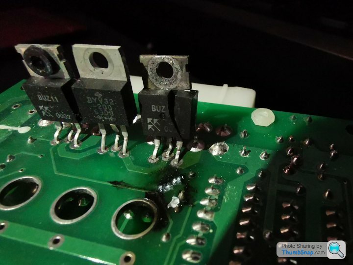
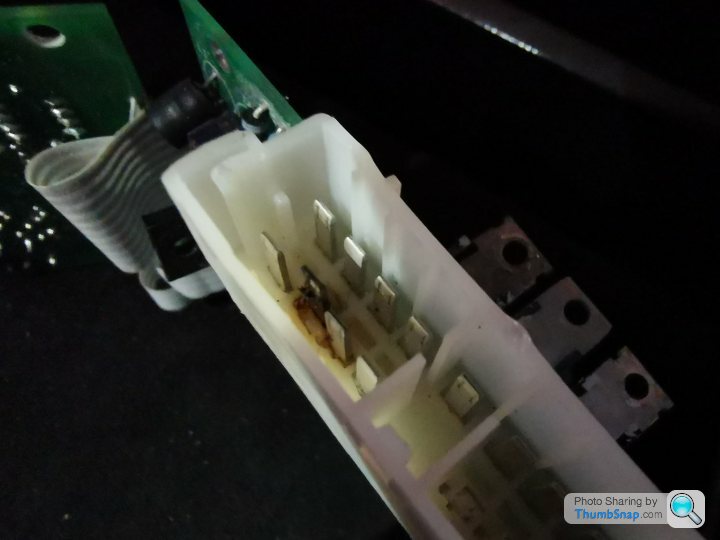
Replacement parts from RS Components only cost a few pounds, but unfortunately you still have to take the fan unit out to clean the motor and oil the bearings. Now runs like new.
This is all retrospective, since that's exactly what happened to mine. I blew the power FET for the hot fan and the increased current melted the board connector.
Replacement parts from RS Components only cost a few pounds, but unfortunately you still have to take the fan unit out to clean the motor and oil the bearings. Now runs like new.
Ok... My hot fan output at the module is restricted by the module itself.
I can take a new 12v to the fan, and get a tiny bit of improvement, as there’s a 1V volt drop, when under load.
However, that variable 0v output from the module to the fan, is the problem. Putting a better 0v feed to the module, still doesn’t improve the 0v output.
Putting a direct 0v feed to the fan, gets me full power.
That HVAC switchpack gives me a 1.5v-2.5v variable output to the controller, which gives me roughly 6v-9.6v at the fan.
Thinking the fan was drawing too much current, I’ve disconnected the fan, and still only get 6-9.6v... so it’s not the fan causing the problem.
I’ve wired the fan directly to the battery, and at start up, it peaks at about 15A for a second, then settles down to 11A.
I suspect the 1.5v-2.5v from the switchpack is correct. My only element of doubt being that when I send 5v to the module, I get full power at the fan. So getting the switchpack modified would solve the problem.
So basically, I don’t know if the switchpack is at fault, the controller is at fault, or it’s designed in, because they don’t want the fan on full whack
I’m leaning towards throwing a switched 0V at it, for when I want maximum attack. Rather than throwing money at parts.
Will’s fix is the best outcome for me
Edited by RUSSELLM on Saturday 30th May 13:53

I’ve ordered some wire and an inline fuse, to improve that 12v. That basically gives me an extra 1V
I’ve got a ground wire from the roll cage, ready to go to a switch, and that gets me closer to 12V when I want full blast.
It’s not doing too bad. I’ve seen it running at 10.5V, just from the controller at times, then 9.6V at other times

Also ordered some jubilee clips to hold that hose on. That was just pushed on originally. That blower’s plenty powerful enough, without the hose on. You can feel it hitting you in the back seats
:Edited by RUSSELLM on Saturday 30th May 18:43
Finally got this done, today.
By the time the 12v+ travels from the front of the car, to the rear fuse box, then back to the HVAC fans, there’s a 1V drop. So I’ve fitted a new feed from the battery. That gets me 10.5v with the fan running.
I’ve run an ‘overide’ ground via a switch, to bypass the HVAC module, that gives me full power when required... Well 11.5v when running... But that’s good enough for now.
Car needs rewiring really, or keep fire fighting the high current draw stuff, like I’ve been doing
With the window relay fix and the HVAC fix, I’ve now ran 4 new wires through the bulkhead grommet, and that’s just to fix the passenger side.
What I did notice, was the positive feed from the battery, goes to a heavy duty fuse in the pax footwell, then on to the rear fuse box. I’m going to see if I can find a small fuse box to replace that fuse. Something to hold 4 relays and 4 fuses would do me. I’ll replace that short positive lead from the battery at the same time, as it looks a bit tired.
Gassing Station | Cerbera | Top of Page | What's New | My Stuff