Algebra for beginners
Discussion


Hi Gang,
Soryy to be begging during a Bank Holiday
BUT
I was trying to connect the wiring for my Oil Pressure Guage.
I am the least talented person with electrics.
In an effort to access the guages I thought that I would remove the plate in which the Clock and Petrol Guage sit.
To access the Allen screws which locate it I decided to remove the Steering Wheel
I had managed to label two of the 2-pin plugs before the event
BUT the Steering Wheel fell.

and has left the four 2-pin plugs free....

Sooooooooooooooo, mt questions are....
From what I could see, I believed that
on the Offside of the wheel
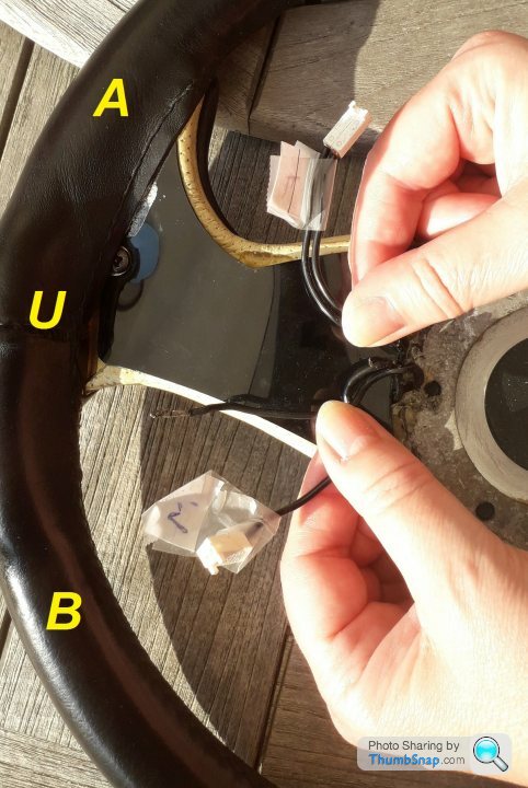
A) is Main Beam
B) is Horn
There is also a disconnected wire (U) which I believe popped out of the Horn plug.
On the Nearside of the Wheel remain

C) Wipe
D) Wash
Now, I am assuming those functions for those plugs because of the physical layout on the wheel.
Does anyone know how the plugs and pins should be connected ?
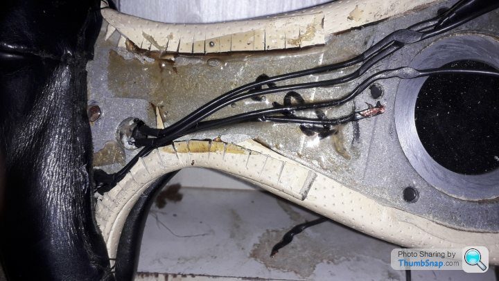
As you will see here, one of the plug wires has broken (O) just at the exit point of the wheel cover (P).
There is one Phillips screw (at point X) If I take this Phillips screw out, will I be able to remove
the covering plate (P) and access the remainder of the wire underneath ?

Sorry that had to be so complicated.
Calculus, a chokkie Bar and a view through the crack in
the Girl's Changing Room Wall for the best answers
Ta !
PJ
Soryy to be begging during a Bank Holiday
BUT
I was trying to connect the wiring for my Oil Pressure Guage.
I am the least talented person with electrics.
In an effort to access the guages I thought that I would remove the plate in which the Clock and Petrol Guage sit.
To access the Allen screws which locate it I decided to remove the Steering Wheel
I had managed to label two of the 2-pin plugs before the event
BUT the Steering Wheel fell.
and has left the four 2-pin plugs free....
Sooooooooooooooo, mt questions are....
From what I could see, I believed that
on the Offside of the wheel
A) is Main Beam
B) is Horn
There is also a disconnected wire (U) which I believe popped out of the Horn plug.
On the Nearside of the Wheel remain
C) Wipe
D) Wash
Now, I am assuming those functions for those plugs because of the physical layout on the wheel.
Does anyone know how the plugs and pins should be connected ?
As you will see here, one of the plug wires has broken (O) just at the exit point of the wheel cover (P).
There is one Phillips screw (at point X) If I take this Phillips screw out, will I be able to remove
the covering plate (P) and access the remainder of the wire underneath ?
Sorry that had to be so complicated.
Calculus, a chokkie Bar and a view through the crack in
the Girl's Changing Room Wall for the best answers
Ta !
PJ
Hi ya Paul.
All normally open buttons, so should have Two wires each.
My best suggestion, would be to turn the ignition on, and short out each pair of pins, to see which set of pins does what.
The connectors in your hand.... Just put a multimeter across the two wires and press a button.... When you get ‘continuity / a dead short / a noise on your multimeter’s buzzer’, you’ll know which connector goes to which button
Edited by RUSSELLM on Saturday 11th April 18:59
RUSSELLM said:
Hi ya Paul.
All normally open buttons, so should have Two wires each.
My best suggestion, would be to turn the ignition on, and short out each pair of pins, to see which set of pins does what.
The connectors in your hand.... Just put a multimeter across the two wires and press a button.... When you get ‘continuity / a dead short / a noise on your multimeter’s buzzer’, you’ll know which connector goes to which button
Cheers Mate.All normally open buttons, so should have Two wires each.
My best suggestion, would be to turn the ignition on, and short out each pair of pins, to see which set of pins does what.
The connectors in your hand.... Just put a multimeter across the two wires and press a button.... When you get ‘continuity / a dead short / a noise on your multimeter’s buzzer’, you’ll know which connector goes to which button
As soon as the Easter Beers wear off I'll try and understand what you've said.
Have a good un, Kiddo !


You may find this of some use for writing notes on

Taken from http://tvr-cerbera.co.uk/WorkshopWiringDiagrams/St...
Taken from http://tvr-cerbera.co.uk/WorkshopWiringDiagrams/St...


Penelope Stopit said:
You may find this of some use for writing notes on
Taken from http://tvr-cerbera.co.uk/WorkshopWiringDiagrams/St...
Cheers Pen,Taken from http://tvr-cerbera.co.uk/WorkshopWiringDiagrams/St...
You're a STAR !
So... back to Work !

Mr Cerbera said:
Penelope Stopit said:
You may find this of some use for writing notes on
Taken from http://tvr-cerbera.co.uk/WorkshopWiringDiagrams/St...
Cheers Pen,Taken from http://tvr-cerbera.co.uk/WorkshopWiringDiagrams/St...
You're a STAR !
So... back to Work !
Your humour never ceases to impress and am not easily impressed
Keep well

RUSSELLM said:
Hi ya Paul.
All normally open buttons, so should have Two wires each.
My best suggestion, would be to turn the ignition on, and short out each pair of pins, to see which set of pins does what.
The connectors in your hand.... Just put a multimeter across the two wires and press a button.... When you get ‘continuity / a dead short / a noise on your multimeter’s buzzer’, you’ll know which connector goes to which button
Yeah this - I had to do the same. I put dots on the plugs, then as it took a couple of weeks, forgot which side I numbered from...All normally open buttons, so should have Two wires each.
My best suggestion, would be to turn the ignition on, and short out each pair of pins, to see which set of pins does what.
The connectors in your hand.... Just put a multimeter across the two wires and press a button.... When you get ‘continuity / a dead short / a noise on your multimeter’s buzzer’, you’ll know which connector goes to which button
Now it has Letters instead H for Horn, etc

Mr Cerbera said:
So there it is.
Remove phillips screw (and countersink) then peel off the protective plate, which is stuck over the cables and ends of leather.
(... and then try and persuade Mark Brown to turn a spacer !)
Mine looked like that, flattened wire which was broken so giving me intermittant wipers, along with the broken ribbon cable. I replaced the wiring, the switches pushed out...Remove phillips screw (and countersink) then peel off the protective plate, which is stuck over the cables and ends of leather.
(... and then try and persuade Mark Brown to turn a spacer !)
Rufus Roughcut said:
Did you find out which wire/plug went where?
98 4.5, my connections as follows:
1 = Headlight Flash
2 = Horn
3 = Washers/Wipers
4 = Wipers
Thanks Rufus Haven't connected the battery up yet.98 4.5, my connections as follows:
1 = Headlight Flash
2 = Horn
3 = Washers/Wipers
4 = Wipers
Still attempting to solder (Looks a bit like the closing scenes in Terminator II)
Byker28i said:
Mine looked like that, ....I replaced the wiring, the switches pushed out...
Hi Dave, thanks !Can you get the wiring, with the appropriate connectors, as a job lot somewhere or did you do it all by hand ?
Ta !
Hi Team,
Having a coupla probs with my Steering Wheels electrics.
Found that the horn cable had snapped.
Found the appaling way TVR had assembled the wheel with the cables trapped between the Boss faces.
Decided to TRY and remedy the situation.
Thought that if I threaded the cables outside the Boss then the problem would be cured.
Although I ground grooves in te Cable protection plates on the back of the wheel....

I realised that, by travelling around the outside, then the Molex Connector Housings were under too much stress on
the shorter RHS,
so
I decided to splice some cable extensions in.
Unfortunately the size of the cable junction blocks I used made it impossible to close the whole thing up while
the Boss was on the Column
so
I decided to follow Byker28i's advice and remove the Boss....
BUT
ater having removed the Steering Adjustment Bolt and unclipping the Ribbon Cables,
when I try and slide the (Triangular) column off, there is a heavy 'clunk' as the collar
- that I've labelled below (from Dave's edited pic) -
bangs into some sort of Stop that is mounted on the chassis, hanging down

Has anyone had any success with Dave's method
OR
Found an alternative way to get the Boss into your hands ?
Thanks all !
PJ
Having a coupla probs with my Steering Wheels electrics.
Found that the horn cable had snapped.
Found the appaling way TVR had assembled the wheel with the cables trapped between the Boss faces.
Decided to TRY and remedy the situation.
Thought that if I threaded the cables outside the Boss then the problem would be cured.
Although I ground grooves in te Cable protection plates on the back of the wheel....
I realised that, by travelling around the outside, then the Molex Connector Housings were under too much stress on
the shorter RHS,
so
I decided to splice some cable extensions in.
Unfortunately the size of the cable junction blocks I used made it impossible to close the whole thing up while
the Boss was on the Column
so
I decided to follow Byker28i's advice and remove the Boss....
Byker28i said:
....
"Just take the bolt out the steering column adjustment,
disconnect a blue and black plug and
disconnect the air vent pipe and ribbon cables - Voila
Now, I know that I'm a Numpty "Just take the bolt out the steering column adjustment,
disconnect a blue and black plug and
disconnect the air vent pipe and ribbon cables - Voila
BUT
ater having removed the Steering Adjustment Bolt and unclipping the Ribbon Cables,
when I try and slide the (Triangular) column off, there is a heavy 'clunk' as the collar
- that I've labelled below (from Dave's edited pic) -
bangs into some sort of Stop that is mounted on the chassis, hanging down
Has anyone had any success with Dave's method
OR
Found an alternative way to get the Boss into your hands ?
Thanks all !
PJ
Edited by Mr Cerbera on Tuesday 19th May 14:28
Or you could just solder some extensions in to the steering wheel button wires and seal them up with heatshrink.
I've removed the upper part of the steering column by undoing the 2 bolts that mount it to the cross member then you can remove it complete with the adjuster assembly, just needs the electrics disconnecting.
I've removed the upper part of the steering column by undoing the 2 bolts that mount it to the cross member then you can remove it complete with the adjuster assembly, just needs the electrics disconnecting.
Edited by CerbWill on Tuesday 19th May 14:39
Just unbolt it from the steering column and screw it back onto the steering wheel. Pop the black plastic TVR logo out of the steering wheel to give access to the bolt when re-attaching to the steering column. Then glue the plastic logo back in with evo stick.
The original connectors do go on ok if you route the wires correctly.
The original connectors do go on ok if you route the wires correctly.


CerbWill said:
Or you could just solder some extensions in to the steering wheel button wires and seal them up with heatshrink.
Aha ! You haven't seen my ability with a soldering iron CerbWill said:
I've removed the upper part of the steering column by undoing the 2 bolts that mount it to the cross member then you can remove it complete with the adjuster assembly, just needs the electrics disconnecting.
Done all that ! 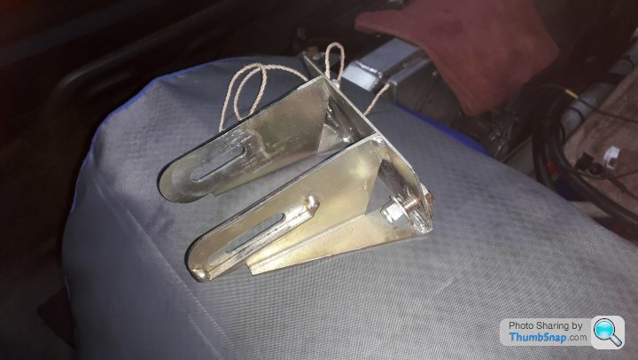
Still won't mudge !
The Clunk feels so solid that it feels as if it is an anchor in the Column
so I'm gonna take the Bolt out tomoz and watch it fall gently into my hand

Edited by Mr Cerbera on Tuesday 19th May 19:41
Gassing Station | Cerbera | Top of Page | What's New | My Stuff