Half the car is dead :-(
Discussion


CerbWill said:
I've been working on some arduino code for the heater ECU. Shared from my google drive here. https://docs.google.com/spreadsheets/d/1O0YG_P0mk7...
My heater box works currently but I have checked this with a very shoddily assembled set of hardware (Arduino Mega with relay & MOSFET boards attached and a step down converter PSU or 2) and it worked on my car. Being an early car mine has the added complication of a solenoid controlled flap in the output from the heater box. First time I've done any sort of coding so it took a while and there may well be a neater way of doing it for people who do this more often. Given my heater box works (thanks Jody!) and I've got bigger problems (leaking water pump) to fix I've given up on this for now.
Hello, I had read your previous comments about this, and was going to contact you about it My heater box works currently but I have checked this with a very shoddily assembled set of hardware (Arduino Mega with relay & MOSFET boards attached and a step down converter PSU or 2) and it worked on my car. Being an early car mine has the added complication of a solenoid controlled flap in the output from the heater box. First time I've done any sort of coding so it took a while and there may well be a neater way of doing it for people who do this more often. Given my heater box works (thanks Jody!) and I've got bigger problems (leaking water pump) to fix I've given up on this for now.

Mine is on it's last legs, so I'll be looking at replacing it. Thank you for sharing your work, this thread could end up being one of the most useful on PH for TVR owners
Juddder said:
Penelope Stopit said:
Are we all to sit back and watch or are you open to input?
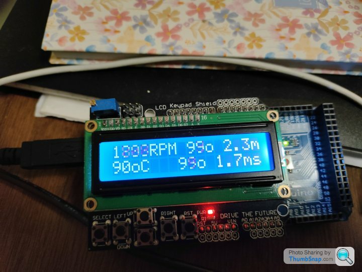
Yes please - I'm just working away on my own so all input very welcomeI'll also share the Arduino ECU diagnostics I built when I was working with Ade (RSAJP) and Greg (OSAJP) on an Arduino version - shows what these little Arduinos can do with a shield or two

Liking the Arduino ECU diagnostics
Asked about input from others as didn't want to be seen as jumping in on your great idea for any reason other than giving possible help
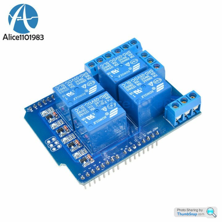
Something that stood out like a sore thumb was the current carrying capacity of a relay shield relay
Max relay current looks to be 8 Amps which is very likely to be far too low for powering window motors especially during motor start up and motor lock-up
Have no idea of the current limitations of the PCB tracks
I forget how much current a door lock actuator draws
Anyway, there's nothing stopping you from powering other larger relays from the relay shield for a prototype or using a different relay board with optocoupler technology similar to what was posted earlier in this topic
Penelope Stopit said:
Max relay current looks to be 8 Amps which is very likely to be far too low for powering window motors especially during motor start up and motor lock-up
No problems and good to have some input and yes your right even if the Arduino itself can't power the circuit as the relay isn't high enough current then we trigger another relay which does the same type of thing, just a bit more long windedThe actual boards I bought have a 10Amp at 24VDC relay on them and in this YouTube video where

Still worth trying out and we'll see how well / slowly it works etc. or not
- Addendum -
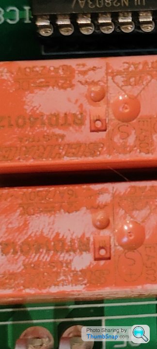
Just checked my Door Control ECU PCB photos and the SCHRACK Relays are 10Amp rated, so those are probably the door latch, and door lock and because those are just pulsed I believe that should be fine with the 10Amp ones on the Arduino

Also, if you look at the bottom of the relay shield PCB, the tracks for the high current part, i.e. the relay, are much thicker than the normal tracks, so designed for this high current

The window relays I'm guessing are these 4 which are RTD14012 SPDT 16 A 12VDC so 16Amp rated so we might need to trigger equivalents of those separately
Edited by Juddder on Saturday 8th January 12:58
Juddder said:
No problems and good to have some input and yes your right even if the Arduino itself can't power the circuit as the relay isn't high enough current then we trigger another relay which does the same type of thing, just a bit more long winded
Ok ThenJuddder said:
Just checked my Door Control ECU PCB photos and the SCHRACK Relays are 10Amp at 240VAC 5Amp at 25VDC, so those are probably the door latch, and door lock and because those are just pulsed I believe that should be fine with the 10Amp ones on the Arduino
Regarding the current ratings of the SCHRACK Relays that read as 10A/5A (NO/NC)This tells us that the NO contacts will carry 10 Amps and the NC contacts will carry 5 Amps
@240VAC or 28VDC
12 Volts won't be a problem
Had to ask Google about the TV Rating which proved to be very interesting
Juddder said:
The window relays I'm guessing are these 4 which are 16Amp rated so we might need to trigger equivalents of those separately
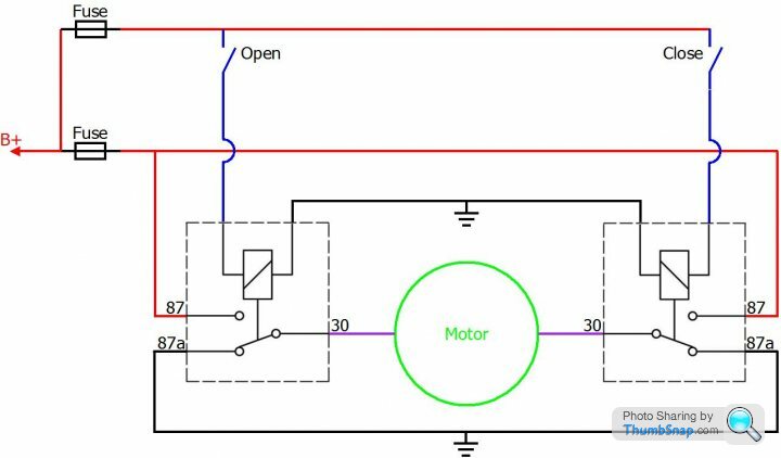
Yes, might be worth measuring window motor current draw @ start-up, run and lock-up, a known lock-up figure might give you ideas about a current sensor circuit that drops the glass if someones head is trapped by the neckDoes the following polarity reverser circuit help you in any way if wanting to use simple 1 wire for up and 1 wire for down signals from the window switches to the Arduino?
Juddder said:
Penelope Stopit said:
Max relay current looks to be 8 Amps which is very likely to be far too low for powering window motors especially during motor start up and motor lock-up
No problems and good to have some input and yes your right even if the Arduino itself can't power the circuit as the relay isn't high enough current then we trigger another relay which does the same type of thing, just a bit more long windedThe actual boards I bought have a 10Amp at 24VDC relay on them and in this YouTube video where
Still worth trying out and we'll see how well / slowly it works etc. or not
- Addendum -
Just checked my Door Control ECU PCB photos and the SCHRACK Relays are 10Amp rated, so those are probably the door latch, and door lock and because those are just pulsed I believe that should be fine with the 10Amp ones on the Arduino
Also, if you look at the bottom of the relay shield PCB, the tracks for the high current part, i.e. the relay, are much thicker than the normal tracks, so designed for this high current
The window relays I'm guessing are these 4 which are RTD14012 SPDT 16 A 12VDC so 16Amp rated so we might need to trigger equivalents of those separately
Edited by Juddder on Saturday 8th January 12:58
Using ohms law of volt x amps to determine the wattage rating of the window motor it works out at 12 (volts) x 11 (amps) = 130 watts give or take a gnats wotsit. Also if you take the headlight bulbs to be 60 watts each, divide the watts by voltage to determine the current drawn, so 60(watts) divided by 12 (volts) = 5 amps per bulb plus sidelights and tail lights to take into account.
Are your test bulbs 100 watts each being powered by 24 vdc and drawing 4 amps per bulb?
Keep plugging away !
So the test hardware arrived and I'm still away from my car, but hopefully from the video below you can see the idea of what I'm trying to do for the Door Control ECU replacement
Relay 1 = Door Unlock
Relay 2 = Door Latch
Relay 3 = Window Down
Basically I'm trying to emulated the existing behaviour where it unlocks the door, drops the window for x amount of seconds, pulses the door latch and then re-enables the lock after y amount of time (*this may not be necessary and / or correct)
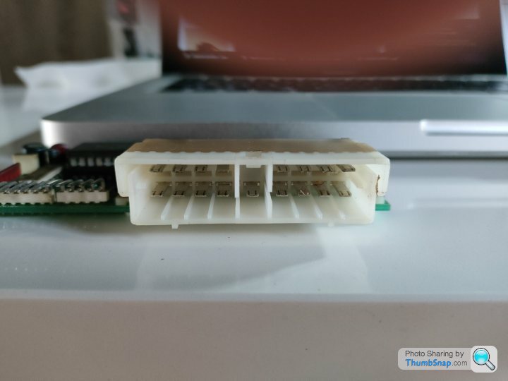
...and just to give a size comparison of how small these boxes are - we can easily use one for each door if we need to (*remember kids, smoking kills!)

Relay 1 = Door Unlock
Relay 2 = Door Latch
Relay 3 = Window Down
Basically I'm trying to emulated the existing behaviour where it unlocks the door, drops the window for x amount of seconds, pulses the door latch and then re-enables the lock after y amount of time (*this may not be necessary and / or correct)
...and just to give a size comparison of how small these boxes are - we can easily use one for each door if we need to (*remember kids, smoking kills!)
Edited by Juddder on Monday 10th January 18:55
CerbWill said:
I've been working on some arduino code for the heater ECU. Shared from my Google Drive here.
https://drive.google.com/file/d/11IcblepCbE1gJqaWl...
My heater box works currently but I have checked this with a very shoddily assembled set of hardware (Arduino Mega with relay & MOSFET boards attached and a step down converter PSU or 2) and it worked on my car. Being an early car mine has the added complication of a solenoid controlled flap in the output from the heater box. First time I've done any sort of coding so it took a while and there may well be a neater way of doing it for people who do this more often. Given my heater box works (thanks Jody!) and I've got bigger problems (leaking water pump) to fix I've given up on this for now.
Damn, blast, can't see your Google filehttps://drive.google.com/file/d/11IcblepCbE1gJqaWl...
My heater box works currently but I have checked this with a very shoddily assembled set of hardware (Arduino Mega with relay & MOSFET boards attached and a step down converter PSU or 2) and it worked on my car. Being an early car mine has the added complication of a solenoid controlled flap in the output from the heater box. First time I've done any sort of coding so it took a while and there may well be a neater way of doing it for people who do this more often. Given my heater box works (thanks Jody!) and I've got bigger problems (leaking water pump) to fix I've given up on this for now.

Door Control - ECU investigation: Day 3
So it's cold and miserable outside and I couldn't be asked to stand around in the cold outside testing with the car, so I put the Door Control ECU on the kitchen side and did some more investigations using a 12V switching power supply
With power connected to J46 (the power for the TTL logic board) and J47 (the power for the door lock relays and the boot lock relay) I can simulate the behaviour of when the Door ECU is powered on by the car
When this happens the first thing it does is apply power to the 4 door lock relays on pins B2, B3, B4 and B5. You can audibly hear them fire as I turn the power on and off below, and measuring between their pins and grounds gives +12V whereas other pins such as A1 [boot lock] and B1 [interior light] and all 0V (GND)

My strategy was to pick a very simple circuit to try and test the Door ECU activation with, and probably the simplest on the whole car is the boot button circuit, as it is actually away from the rest of the mess in the front and is just a simple switch in the boot
If you look at the circuit diagrams as to how this is triggered, by default it is floating, and probably pulled to high (+5V) using a pull-up resistor or similar
When the switch is pressed it is connected to GND and the value of that pin should drop to 0V

Trying this using a jumper lead between connector J45 -> pin A8 and GND results in no obvious relay switching so I am wondering if it is tied to the alarm in some way
Tracing J45 -> pin B3 on the Circuit Diagram connects it to the Alarm ECU J36 on pin 5 which is the Alarm State.

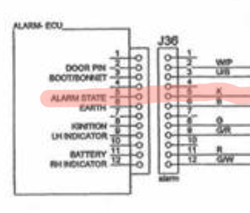
My logic is that if I can either pull this to GND or to +5V like other TTL true or false values I should be able to simulate disabling the alarm, and thus when I then simulate the boot switch being pressed by pulling that to GND is should trigger J37 -> pin A1 which is the BOOT LOCK DRIVE
Does anyone know what this value is by default and which way around it goes when the alarm is disabled?
So it's cold and miserable outside and I couldn't be asked to stand around in the cold outside testing with the car, so I put the Door Control ECU on the kitchen side and did some more investigations using a 12V switching power supply
With power connected to J46 (the power for the TTL logic board) and J47 (the power for the door lock relays and the boot lock relay) I can simulate the behaviour of when the Door ECU is powered on by the car
When this happens the first thing it does is apply power to the 4 door lock relays on pins B2, B3, B4 and B5. You can audibly hear them fire as I turn the power on and off below, and measuring between their pins and grounds gives +12V whereas other pins such as A1 [boot lock] and B1 [interior light] and all 0V (GND)
My strategy was to pick a very simple circuit to try and test the Door ECU activation with, and probably the simplest on the whole car is the boot button circuit, as it is actually away from the rest of the mess in the front and is just a simple switch in the boot
If you look at the circuit diagrams as to how this is triggered, by default it is floating, and probably pulled to high (+5V) using a pull-up resistor or similar
When the switch is pressed it is connected to GND and the value of that pin should drop to 0V
Trying this using a jumper lead between connector J45 -> pin A8 and GND results in no obvious relay switching so I am wondering if it is tied to the alarm in some way
Tracing J45 -> pin B3 on the Circuit Diagram connects it to the Alarm ECU J36 on pin 5 which is the Alarm State.
My logic is that if I can either pull this to GND or to +5V like other TTL true or false values I should be able to simulate disabling the alarm, and thus when I then simulate the boot switch being pressed by pulling that to GND is should trigger J37 -> pin A1 which is the BOOT LOCK DRIVE
Does anyone know what this value is by default and which way around it goes when the alarm is disabled?
Penelope Stopit said:
Been a spanner and linked the wrong file.https://drive.google.com/file/d/11IcblepCbE1gJqaWl...
Hopefully the right one.
Does this
Any idea what this pin is meant to get fed from the Alarm?
Also, the only reference I can see on the Door Control ECU to LED (the green flashing LED on the centre console) is pin B3, J48 which is labelled 'LED DRIVE'
I'm wondering if the Door Control ECU not being connected completely means it starts sending panic signals to the LED DRIVE - of course would be nice if TVR had ever documented any of this!!Found here https://www.pistonheads.com/gassing/topic.asp?h=0&...
verify that the Pink is low when the alarm is unarmed
Juddder said:
tofts said:
Check the pink wire (on the door control unit), if this gets lifted from ground whilst car is unarmed the module will do odd things.
So on the wiring diagrams, Pink is colour 'K' and from the Rear Harness Part 1 diagram here that would be pin B3, J45 on the Door Control ECU which is labelled as 'Alarm Input'Any idea what this pin is meant to get fed from the Alarm?
Also, the only reference I can see on the Door Control ECU to LED (the green flashing LED on the centre console) is pin B3, J48 which is labelled 'LED DRIVE'
I'm wondering if the Door Control ECU not being connected completely means it starts sending panic signals to the LED DRIVE - of course would be nice if TVR had ever documented any of this!!
verify that the Pink is low when the alarm is unarmed
CerbWill said:
Penelope Stopit said:
Been a spanner and linked the wrong file.https://drive.google.com/file/d/11IcblepCbE1gJqaWl...
Hopefully the right one.
Will take a longer look later
This is very interesting
Please bear in mind that Arduino projects with code are new to me but we all have to start somewhere
Enjoying this and hope it works for you, lots of work hey
DuncanM said:
I wouldn't wish the electronic failures on anyone, but in the nicest possible way, if they did have to happen to someone, Alex is the perfect chap to work through the issues. Could end up being amazing for us fellow owners
Ha! Thanks Duncan Truthfully I'd wish it not to happen for anyone as it really is a pain in the hearse but hey as you say if it is going to happen to anyone, more handy if you have some vague idea what you are doing in this area Penelope Stopit said:
Found here https://www.pistonheads.com/gassing/topic.asp?h=0&...
verify that the Pink is low when the alarm is unarmed
Oh that's handy and funnily enough I've just gone out and tested exactly the same!verify that the Pink is low when the alarm is unarmed
I multi-metered between J45 pin B3 - Alarm Input (K) and J46 pin A1 - Earth (B) and can verify that when the alarm is disabled there is a 0V current on the Alarm Input.

As the alarm turns back on this raises to ~ +9V (guessing a low +12V)
I'm guessing from my testing yesterday that as the pin wasn't connected the relays turn on as if the car is alarmed as the input was floating. I'll try grounding it and see what those relays then do.
Also rhetorical question but does this mean that there is a constant 12V to each of these four relays when the alarm is enabled, in another words all of the time the car is parked? If so that will slowly be one of the things draining the battery...
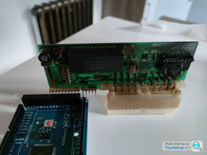
Steering Wheel Functions Control Unit investigation: Day 1
First thing first with this board was to mark up all of the pins and see if we can do anything with our initial investigation as it looks due to the burn damage that it's going to be difficult to repair so we might need to replace it too.
A couple of interesting observations:
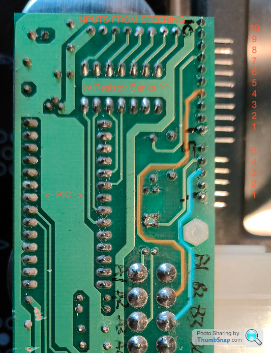
- The HAZARD SWITCH (5 pin connector pin 3 in Blue) and the HORN INPUT (10 pin connector pin 4 in Orange) go straight through to the harness connector bypassing any electronics
- All of the other steering wheel inputs are fed into resistor banks for pull-up(?) to +5V for logic 1 by default and then into the PIC for actioning as when the buttons are closed they connect to GND to give logic 0
So as with the other boards first thing first is to record all of the inputs and outputs:
The 5 pin and 10 pin ribbon connectors aren't keyed so we need to find out which way around the connectors will go else we have a good chance of blowing up our board / Arduino when we reconnect it as +12V is on pin 7 which could be pin 3 if we connect it the wrong way around!
Looking at the wiring diagram, the only GND is pin 10 on the 10 pin ribbon connector, but as it's not keyed we don't know whether that is with the silver contacts facing up, or facing down
So I had a cunning plan which is to connect some long pins to the 10 pin connector, put the meter in continuity mode and then test with one of the switches on the steering wheel and GND
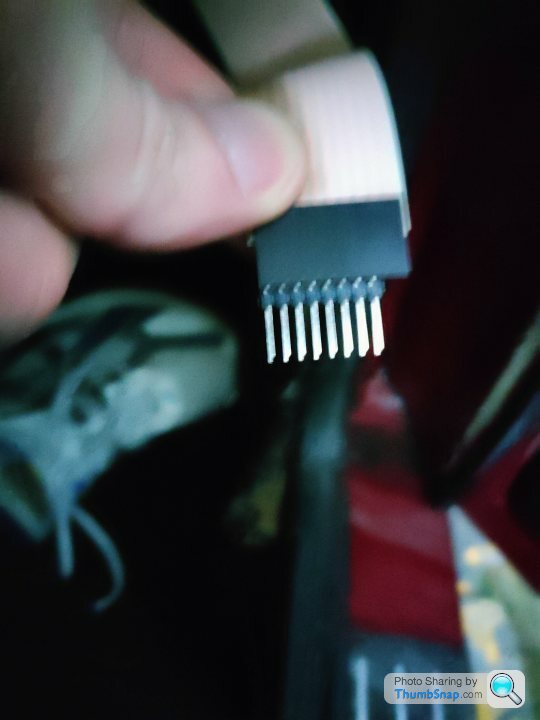
The Wiper Input looks like a good one to go for as it is pin 1 on the connector. Here's it being tested so at least we know which way around we need these ribbons for our board (the beep is what happens from the multimeter when connection is made)
My thoughts are that the role of the PIC is to take the indicator cancel signal from the steering wheel column mounted optical sensors and decide whether to cancel the indicators or not. If so we can easily emulate that with an Arduino and the spacing on the pins is the same so we can piggy back the existing ribbon connectors directly to our Arduino
Does anyone know what manufacture would have made these plugs and sockets because if I can find some matching ones we can probably pretty easily make an Arduino shield that we can solder this to and mount the Arduino on top
BTW one of the brokers quoted me £200 quid for one of these units and that was even if they had one, so making our own seems like a nice option for everyone if they need one in the future
First thing first with this board was to mark up all of the pins and see if we can do anything with our initial investigation as it looks due to the burn damage that it's going to be difficult to repair so we might need to replace it too.
A couple of interesting observations:
- The HAZARD SWITCH (5 pin connector pin 3 in Blue) and the HORN INPUT (10 pin connector pin 4 in Orange) go straight through to the harness connector bypassing any electronics
- All of the other steering wheel inputs are fed into resistor banks for pull-up(?) to +5V for logic 1 by default and then into the PIC for actioning as when the buttons are closed they connect to GND to give logic 0
So as with the other boards first thing first is to record all of the inputs and outputs:
Steering Wheel Functions Control Unit

A1 - N/C
A2 - HEADLAMP SIGNAL
A3 - N/C
A4 - N/C

A6 - WIPER 2 SIGNAL
A7 - MAIN BEAM SIGNAL
A8 - DIP BEAM SIGNAL
A9 - TURN LEFT SIGNAL

B1 - IGNITION
B2 - HORN DRIVE
B3 - HAZARD DRIVE
B4 - BATTERY
B5 - GND
B6 - WIPER 1 SIGNAL
B7 - N/C
B8 - WASHER SIGNAL
B9 - TURN RIGHT SIGNAL

10 Pin Ribbon

10 - GND
9 - CANCEL RHT IP
8 - CANCEL LEFT IP
7 - +12V
6 - N/C
5 - N/C
4 - HORN INPUT
3 - DIP / MAIN
2 - WASHER INPUT
1 - WIPER INPUT

5 Pin Ribbon

5 - N/C
4 - HAZARD W/L
3 - HAZARD SWITCH
2 - INDICATOR RIGHT
1 - INDICATOR LEFT
The 5 pin and 10 pin ribbon connectors aren't keyed so we need to find out which way around the connectors will go else we have a good chance of blowing up our board / Arduino when we reconnect it as +12V is on pin 7 which could be pin 3 if we connect it the wrong way around!
Looking at the wiring diagram, the only GND is pin 10 on the 10 pin ribbon connector, but as it's not keyed we don't know whether that is with the silver contacts facing up, or facing down
So I had a cunning plan which is to connect some long pins to the 10 pin connector, put the meter in continuity mode and then test with one of the switches on the steering wheel and GND
The Wiper Input looks like a good one to go for as it is pin 1 on the connector. Here's it being tested so at least we know which way around we need these ribbons for our board (the beep is what happens from the multimeter when connection is made)
My thoughts are that the role of the PIC is to take the indicator cancel signal from the steering wheel column mounted optical sensors and decide whether to cancel the indicators or not. If so we can easily emulate that with an Arduino and the spacing on the pins is the same so we can piggy back the existing ribbon connectors directly to our Arduino
Does anyone know what manufacture would have made these plugs and sockets because if I can find some matching ones we can probably pretty easily make an Arduino shield that we can solder this to and mount the Arduino on top
BTW one of the brokers quoted me £200 quid for one of these units and that was even if they had one, so making our own seems like a nice option for everyone if they need one in the future
Edited by Juddder on Sunday 16th January 18:05
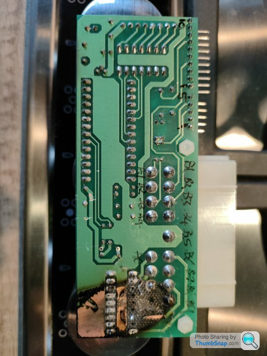
One other note for my own analysis is that the wiring diagram has A1 and A3 as N/C (Not Connected) but as you can see in the photos below there are definitely connections on there (in Orange) as we know that A1 is the middle pin as that is labelled on the top of the board and A is keyed
Bottom:

Top:

Wiring Diagram:

Bottom:
Top:
Wiring Diagram:
Steering Wheel Functions Control Unit investigation: Day 2
So they say a picture says a 1,000 words (or something like that) so here's two pictures and a couple of videos of my replacement Steering Wheel Functions Control Unit Arduino.


Thing to note for others in the future is that the all black side of the ribbon connectors is the top, and the side that shows the silver pins through windows is the bottom - might not be the same for everyone but seems logical
So they say a picture says a 1,000 words (or something like that) so here's two pictures and a couple of videos of my replacement Steering Wheel Functions Control Unit Arduino.
Thing to note for others in the future is that the all black side of the ribbon connectors is the top, and the side that shows the silver pins through windows is the bottom - might not be the same for everyone but seems logical
Gassing Station | Cerbera | Top of Page | What's New | My Stuff