Half the car is dead :-(
Discussion


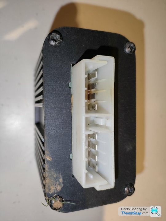
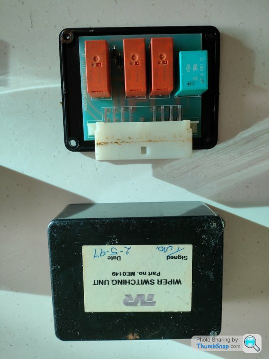
So my replacement Wiper Switching Unit has arrived so the first thing to do is take it apart and try and work out why the other unit is causing the Washer Pump to run continuously
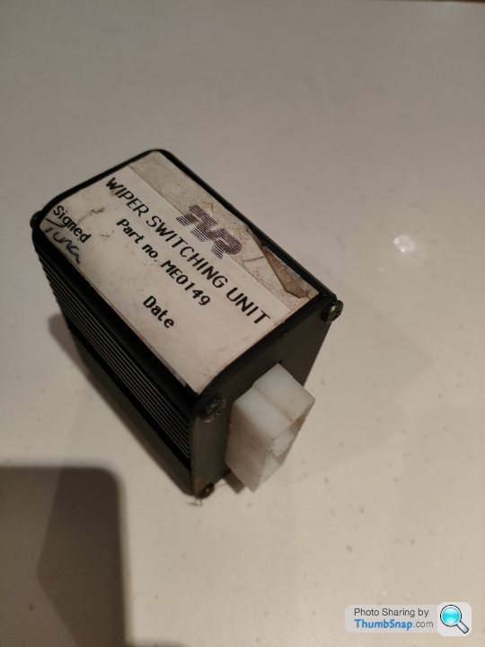
The replacement unit has some corrosion or burn on two of the pins so I'll tidy that up
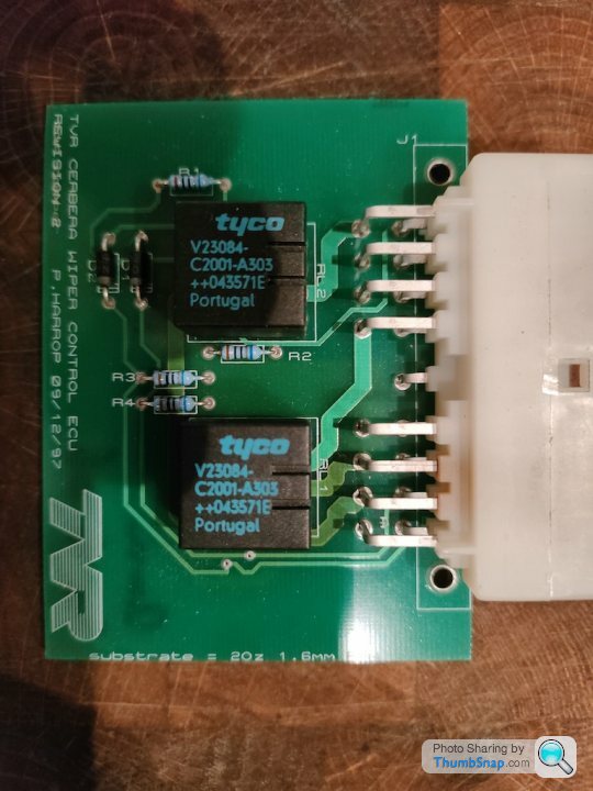
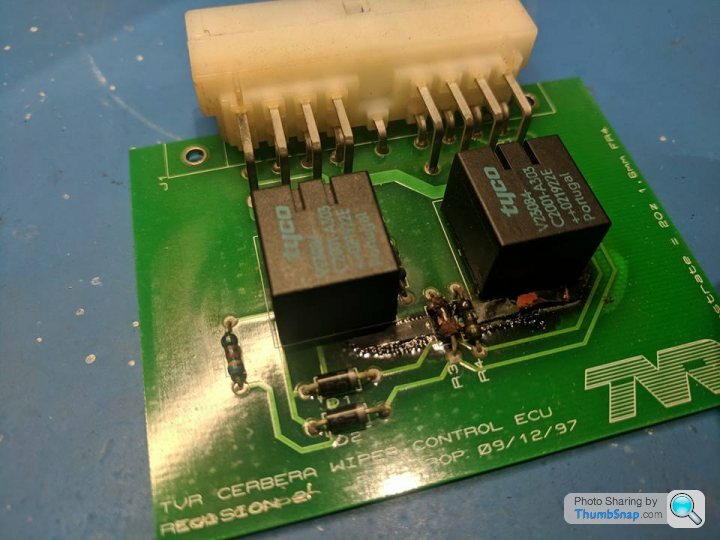
The PCB itself is much more modern than the other Control Box PCBs in that it is two layered (top and bottom) and has Dual Mini Relays on it to save space rather than single larger Relays
Top Layer
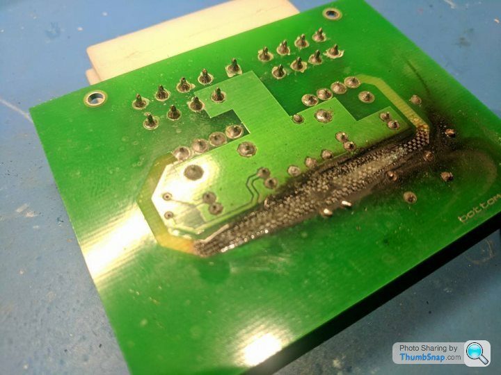
Bottom Layer
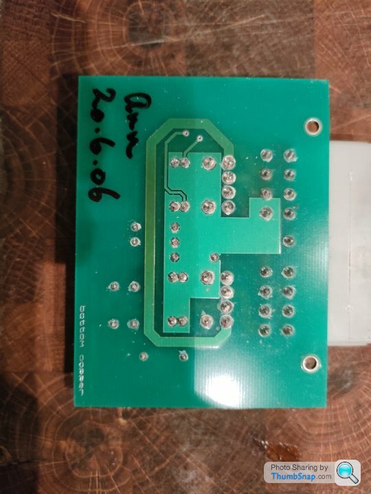
The majority of the bottom layer is being used to share the +12V Ignition Input around to the other parts of the circuit, whereas the 4 main drive lines are on the top board which are for Wiper speed 1, Wiper speed 2, Washer and Wiper Park Disengage
Basically as the inputs for Wiper Speed 1 or Wiper Speed 2 trigger their relays to give +12V to the Wiper motor at Speed 1 or Speed 2, they also trigger the second half of relay R2 to send +12V to the PARK SWITCH IN which tells the wipers not to park and is a relay near or by the Wiper Motor
That counts for 3 of the 4 relays, and the other half of Relay 2 is used to trigger the Washer Pump from the Washer Input
I've tested everything on the boards and it all looks good so I'll clean it up and test it out when I'm next with my car
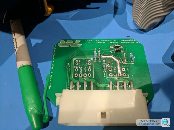
Here's the pin outs, wire colours and parts list to keep everything documented
The replacement unit has some corrosion or burn on two of the pins so I'll tidy that up
The PCB itself is much more modern than the other Control Box PCBs in that it is two layered (top and bottom) and has Dual Mini Relays on it to save space rather than single larger Relays
Top Layer
Bottom Layer
The majority of the bottom layer is being used to share the +12V Ignition Input around to the other parts of the circuit, whereas the 4 main drive lines are on the top board which are for Wiper speed 1, Wiper speed 2, Washer and Wiper Park Disengage
Basically as the inputs for Wiper Speed 1 or Wiper Speed 2 trigger their relays to give +12V to the Wiper motor at Speed 1 or Speed 2, they also trigger the second half of relay R2 to send +12V to the PARK SWITCH IN which tells the wipers not to park and is a relay near or by the Wiper Motor
That counts for 3 of the 4 relays, and the other half of Relay 2 is used to trigger the Washer Pump from the Washer Input
I've tested everything on the boards and it all looks good so I'll clean it up and test it out when I'm next with my car
Here's the pin outs, wire colours and parts list to keep everything documented
Wiper Switching Unit (J28)

A1 - N/C
A2 - PARK SWITCH IN [N/G] [OUTPUT] - TELLS THE WIPERS TO NOT PARK
A3 - SPEED 1 DRIVE [U/G] [OUTPUT] - POWER WIPER MOTOR AT SPEED 1
A4 - IGNITION [O] [INPUT]

A6 - SPEED 2 DRIVE [OUTPUT] - POWER WIPER MOTOR AT SPEED 2
A7 - N/C
A8 - N/C
A9 - WASHER DRIVE [U/Y] [OUTPUT] - TELLS THE WASHER TO RUN

B1 - WIPER 2 SIGNAL [R/G]
B2 - WIPER 1 SIGNAL [U/O]
B3 - N/C
B4 - N/C
B5 - N/C
B6 - N/C
B7 - N/C
B8 - N/C
B9 - WASHER SIGNAL [U/Y]

Colour Codes

B - BLACK
N - BROWN
R - RED
O - ORANGE
Y - YELLOW
G - GREEN
LTG - LIGHT GREEN
U - BLUE
P - PURPLE
K - PINK
W - WHITE
S - SLATE (GREY)

Parts

2 x DOUBLE MINI RELAYS DMR - tyco V23084 C2001 A303 ++043571E Portugal

RL1
- pin 11 IGNITION +12V
- pin 12 WIPER 1 SIGNAL
- pin 13 IGNITION +12V
- pin 15 SPEED 1 DRIVE
- pin 21 IGNITION +12V
- pin 22 WIPER 2 SIGNAL
- pin 23 IGNITION +12V
- pin 25 SPEED 2 DRIVE

RL2
- pin 11 IGNITION +12V
- pin 12 WASHER SIGNAL
- pin 13 IGNITION +12V
- pin 15 WASHER DRIVE
- pin 21 IGNITION +12V
- pin 22 WIPER 1 SIGNAL OR WIPER 2 SIGNAL
- pin 23 IGNITION +12V
- pin 25 PARK SWITCH IN (DRIVE)

2 x DIODES (D1, D2) - STOP CURRENT BACK FLOW FOR WIPER 1 SIGNAL AND WIPER 2 SIGNAL TO RL2 pin 22
4 x RESISTORS (R1, R2, R3, R4)
Edited by Juddder on Friday 25th November 18:13
4 x RESISTORS (R1, R2, R3, R4)
These I believe are pull-up resistors for the inputs, so that they don't float when not connected to GND (the result of pressing the buttons) and instead "weakly" pull the inputs up to +12V
BTW snooping around Jody @ Python Racing's Facebook page I found some pretty scary pictures of what can happen to this box if it gets power reversed or similar - nice repair from Jody though
Output power line to Wiper Park totally burnt out
and what I think is the power for that Output
and Jody's neat fix
This is all very interesting but what we're all waiting for is for you to come out with a neat box that runs the width of the fuel tank with connectors for all the legacy plugs in the right places that allows us to control everything from our phone over bluetooth  .
.
Seriously though, impressive work figuring all this out
.Seriously though, impressive work figuring all this out
FarmyardPants said:
This is all very interesting but what we're all waiting for is for you to come out with a neat box that runs the width of the fuel tank with connectors for all the legacy plugs in the right places that allows us to control everything from our phone over bluetooth .
Seriously though, impressive work figuring all this out
I could have written this word for word .Seriously though, impressive work figuring all this out

More specifically for moi, excited to see his simple heater ecu replacement howto
DuncanM said:
More specifically for moi, excited to see his simple heater ecu replacement howto
The heater box is luckily one of the very few ones I haven't had to look at so far!Once I've got my last gremlin of the water pump running continuously (if I can find the d*mn box) then it's a swap in for the replacement one and hopefully that all goes away
Then I'd be happy to look into the heater box as I came across a few other heater ECU threads where that had blown up for various owners - similar with the wiper ecu like this one
That thread also quotes two owners as saying the Wiper ECU is in the passenger footwell so I'm wondering if rather than being velcro'd to the passenger footwell wall like the other boxes, that it is instead tucked up into the dashboard where the yellow arrow is below?
One to check on my next trip over to my car with a torch and some nausea inducing contortions lying upside down on the passenger floor!

Juddder said:
Byker28i said:
Missed this, sorry - yes it's in the passenger footwell
Could it possibly be anywhere else because from an initial look in my passenger footwell it's not obviously there afaics!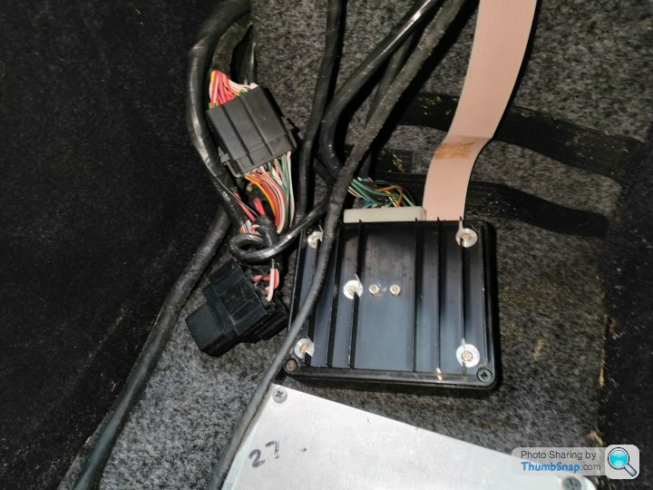
FarmyardPants said:
It might be higher up - cable tied to the horizontal tube near the radio, I think that's where mine is.
Awesome, many thanks - yes we were obviously thinking the same at the same time!How did you access your one - through the radio space or from the bottom of the dash via the passenger footwell?
Taking the dashboard out isn't really on my bucket list of things to do

Edited by Juddder on Friday 27th January 17:55
Juddder said:
Awesome, many thanks - yes we were obviously thinking the same at the same time!
How did you access your one - through the radio space or from the bottom of the dash via the passenger footwell?
Taking the dashboard out isn't really on my bucket list of things to do
It should be to the left of the radio, visible from the footwell. I’ve not had to do anything with mine (yet…)How did you access your one - through the radio space or from the bottom of the dash via the passenger footwell?
Taking the dashboard out isn't really on my bucket list of things to do
Edited by Juddder on Friday 27th January 17:55
Finally got another afternoon with my car (and the sun was out) so I managed to get the final two gremlins fixed and the car is now Fully Functional again - woohoo!
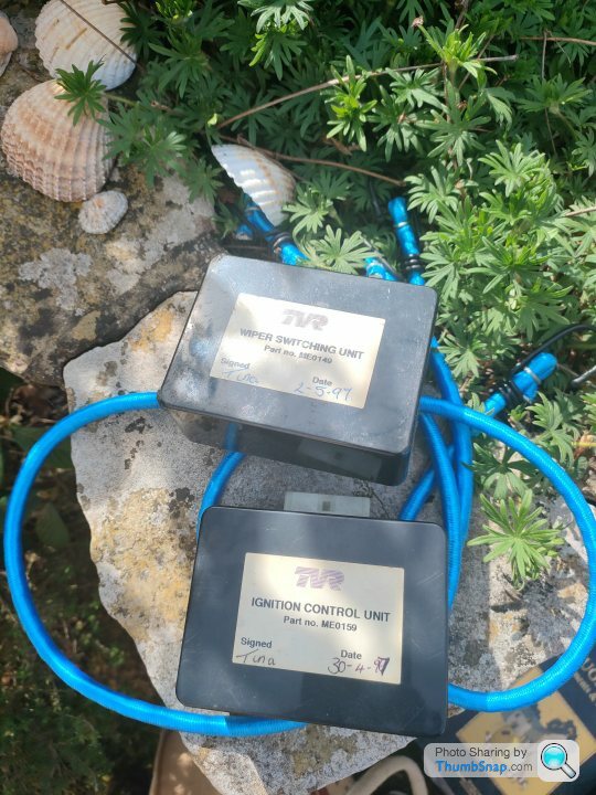
1. Wiper Switching Unit
Symptoms:
Windscreen Washer continually runs
Fix:
First job was to remove the lower F1 panel / scuttle and disconnect the power connectors to the windscreen washer pump and just check that this indeed did work by putting the car in engaged mode and listening for the pump (*unlikely to work with no power) as I can't find a fuse to pull for this pump anywhere on the fuse box or wiring diagrams
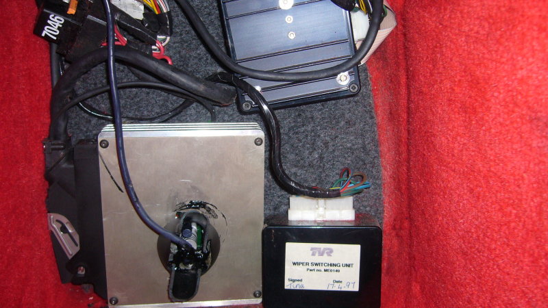
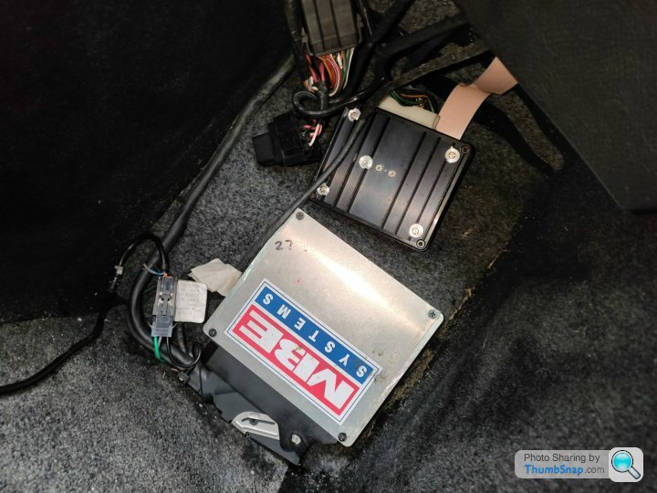
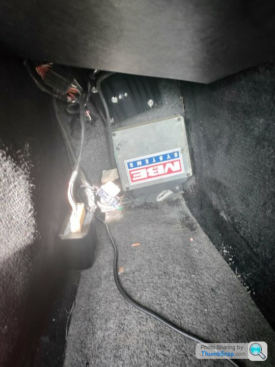
This worked so I went hunting for the Wiper Switching Unit and found it in the passenger footwell, tucked onto the inner lining of the trim that covers the dashboard above the passengers knees. Removed the ECU cover and reached up from the bottom to find it
Replaced with eBay alternative unit, re-connecting power to wiper washer pump and tested
Result:
All working again properly and the wipers and washers run together when the steering wheel button is pressed. Fixed
Wiper Switching Unit (new one) in place in the passenger footwell - needs to be tidied up
Original Wiper Switching Unit (to be investigated)
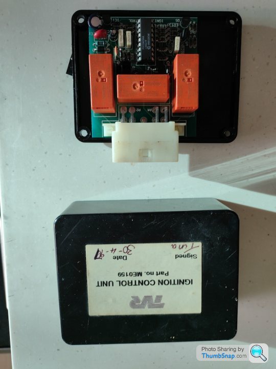
2. Ignition Control Unit
Symptoms:
First time I started the car it started as normal with the green button spinning the starter motor and engaging the engine. After stopping for some tea and then trying again the car refused to start and no results from pressing the green button. Rechecked all of the alarm settings (silver key replacement switch = on, fuel cut-off switch = on) but still no action from pressing the green button
Left the car for 5 minutes then tried again, and the starter started but ran continually and at a much higher pitch than normal and wouldn't stop after releasing the green button. Used the silver key replacement switch to turn off the car
Left for a further 5 minutes and then tried again and continually no response from the car and the normal green button starting process
Fix:
Luckily on my literally-buy-every-cerbera-control-box-on-ebay sweep many months ago I had also bought a replacement Ignition Control Unit so I unplugged the existing unit and replaced it with the new one.
Result:
Car starts perfectly as normal again and the green button functions correctly on multiple tests. Fixed
ignition Control Unit
Summary:
So after what is practically 12 months of diagnostics and replacing / rebuilding / getting fixed / redesigning the various control boxes that blew when the car power shorted I am back with a working Cerbera which I should actually be able to get out and enjoy this summer and doing some driving (*which is what I'm sure someone once told me they were meant to be for rather than a big electronics project :-) )
Alex
1. Wiper Switching Unit
Symptoms:
Windscreen Washer continually runs
Fix:
First job was to remove the lower F1 panel / scuttle and disconnect the power connectors to the windscreen washer pump and just check that this indeed did work by putting the car in engaged mode and listening for the pump (*unlikely to work with no power) as I can't find a fuse to pull for this pump anywhere on the fuse box or wiring diagrams
This worked so I went hunting for the Wiper Switching Unit and found it in the passenger footwell, tucked onto the inner lining of the trim that covers the dashboard above the passengers knees. Removed the ECU cover and reached up from the bottom to find it
Replaced with eBay alternative unit, re-connecting power to wiper washer pump and tested
Result:
All working again properly and the wipers and washers run together when the steering wheel button is pressed. Fixed
Wiper Switching Unit (new one) in place in the passenger footwell - needs to be tidied up
Original Wiper Switching Unit (to be investigated)
2. Ignition Control Unit
Symptoms:
First time I started the car it started as normal with the green button spinning the starter motor and engaging the engine. After stopping for some tea and then trying again the car refused to start and no results from pressing the green button. Rechecked all of the alarm settings (silver key replacement switch = on, fuel cut-off switch = on) but still no action from pressing the green button
Left the car for 5 minutes then tried again, and the starter started but ran continually and at a much higher pitch than normal and wouldn't stop after releasing the green button. Used the silver key replacement switch to turn off the car
Left for a further 5 minutes and then tried again and continually no response from the car and the normal green button starting process
Fix:
Luckily on my literally-buy-every-cerbera-control-box-on-ebay sweep many months ago I had also bought a replacement Ignition Control Unit so I unplugged the existing unit and replaced it with the new one.
Result:
Car starts perfectly as normal again and the green button functions correctly on multiple tests. Fixed
ignition Control Unit
Summary:
So after what is practically 12 months of diagnostics and replacing / rebuilding / getting fixed / redesigning the various control boxes that blew when the car power shorted I am back with a working Cerbera which I should actually be able to get out and enjoy this summer and doing some driving (*which is what I'm sure someone once told me they were meant to be for rather than a big electronics project :-) )
Alex

Is there any possibility that you can explain to all us TVR lovers how removing the fusebox from its original location and dropping into an area of nothing but electrical insulating material such as glass created all the problems
Glass knows It's an insulator
Are we all missing something?
The question was put to you in the past in this topic and you avoided it
What I'm concerned about more than anything else is that Cerbera owners could be frightened away from working on a fuseebox dropped from its original location
Glass knows It's an insulator
Are we all missing something?
The question was put to you in the past in this topic and you avoided it
What I'm concerned about more than anything else is that Cerbera owners could be frightened away from working on a fuseebox dropped from its original location
There are no control unit inputs to a Cerbera fusebox that could possibly damage a Cerbera ECU
Moving on
Why post something as if it's fact when it's impossible that it could happen?
Why has nobody else questioned your comments?
There's something wrong with this topic????? Anybody knowing anything about TVR Cerbera electrics knows that what you've posted about the fusebox shorting out and damaging several ECU's is impossible
No reply expected
Why bother, that is the question
Having a larf is one thing, keeping posting about something that's impossible is another

Thought you all might enjoy this as the forum is relatively quiet at the moment
This is how the Ignition Control Unit works which is one of the boxes on the rear shelf of the car and video showing it being bench tested and how it operates
There's a couple of errors in my video (*just before the eagle eared point them out!) and when I say solenoid initially I mean relay, and when I say B2 is ground that's wrong as A2 is ground, but if you look at the wires and watch the video you will get the idea :-)
The good news is reproducing this box would be pretty easy so if we ever need to do that I can make one now that we know the wiring connections and how it works
The TVR Cerbera uses an Ignition Control Unit to start the car based on the power inputs being present from the battery [A1], and the battery START feed [A5]. By grounding the Start Signal input [B2] when the start button on the steering wheel is pressed the unit turns on the engine [B1] and fires the starter motor [B5]
When the button is released the engine relay [B1] stays on but the start motor relay is released [B5] stopping the starter motor
When the Stop Signal input [B3] from the stop button on the steering wheel is pressed this is then connected to ground and the engine relay is also stopped [B1], stopping the car.
A1 - Battery (IN) [R]
A2 - Ignition Earth [B]
A3 - key
A4 - N/C
A5 - Battery (START) [R]
B1 - Ignition Output [W] = B 15 [W]
B2 - Start Signal [R/W]
B3 - Stop Signal [R/?]
B4 - N/C
B5 - Starter Drive [W/R] = Immobiliser ECU | Starter [Input] (pin 8 W/R) = Immobiliser ECU | Starter [Output] (pin 10 W/R) = D ASL [W/R]
This is how the Ignition Control Unit works which is one of the boxes on the rear shelf of the car and video showing it being bench tested and how it operates
There's a couple of errors in my video (*just before the eagle eared point them out!) and when I say solenoid initially I mean relay, and when I say B2 is ground that's wrong as A2 is ground, but if you look at the wires and watch the video you will get the idea :-)
The good news is reproducing this box would be pretty easy so if we ever need to do that I can make one now that we know the wiring connections and how it works
Bench Testing the TVR Cerbera Ignition Control Unit
The TVR Cerbera uses an Ignition Control Unit to start the car based on the power inputs being present from the battery [A1], and the battery START feed [A5]. By grounding the Start Signal input [B2] when the start button on the steering wheel is pressed the unit turns on the engine [B1] and fires the starter motor [B5]
When the button is released the engine relay [B1] stays on but the start motor relay is released [B5] stopping the starter motor
When the Stop Signal input [B3] from the stop button on the steering wheel is pressed this is then connected to ground and the engine relay is also stopped [B1], stopping the car.
A1 - Battery (IN) [R]
A2 - Ignition Earth [B]
A3 - key
A4 - N/C
A5 - Battery (START) [R]
B1 - Ignition Output [W] = B 15 [W]
B2 - Start Signal [R/W]
B3 - Stop Signal [R/?]
B4 - N/C
B5 - Starter Drive [W/R] = Immobiliser ECU | Starter [Input] (pin 8 W/R) = Immobiliser ECU | Starter [Output] (pin 10 W/R) = D ASL [W/R]
Edited by Juddder on Tuesday 6th June 17:04
Gassing Station | Cerbera | Top of Page | What's New | My Stuff