Half the car is dead :-(
Discussion


Penelope Stopit said:
Don't know what happened to terminal A5 but it won't cause any problems for this job
Nice 
A3 or A5 is missing from most of the pinouts on the wiring diagram as it's the key for the connector so has a missing pin
I did similar to you above with the 3 lights related control boxes, so here's the other two for reference too
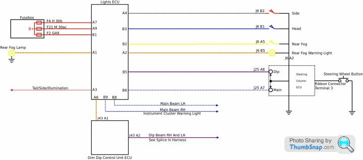
2.1 Lights ECU (J57)
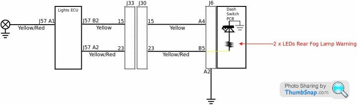
A1 - Rear Fog W/L (Y/R)
A2 - Rear Fog W/L (Y/R)
A3 - Sidelamps (R/W)
A4 - Side Lamp Signal (W)
-
A6 - Dip Beam (R/Y)
A7 - Battery (Dip) (R)
A8 - Ignition (G)
A9 - Battery (Main) (R)
B1 - Battery (Side) (R)
B2 - Fog Lamp Sig (Y)
B3 - Head Lamp Sig (U)
B4 - N/C
B5 - Dip Beam Sig (U/R)
B6 - Main Beam Sig (U/W)
B7 - N/C
B8 - Main Beam (U/W)
B9 - Main Beam (U/W)
2.2 Dim Dip Control Unit - ECU (J43)
B5 - Dip Power (R/Y) [traced from 'Lights ECU']
B4 - Dip Beam Drive (U/R)
B3 - Dim Dip Input (R/B)
B2 - Earth (B)
B1 - Headlamps On (U/Y)
A5 - Main Beam Signal (U/W)
A4 - Ignition (R)
-
A2 - N/C
A1 - N/C
2.3 Dim Dip Unit - ECU (J44-A)
1 - Ignition (G) (Green)
2 - Head Lamps On (U/W) (Blue with White) [traced from 'Dim Dip Control Unit-ECU']
3 - Battery (R) (Red)
4 - Earth (B) (Black)
5 - Side Lamps (R/W) (Red with White)
6 - Dim Dip Output (R/B) (Red with Black) [traced from 'Dim Dip Control Unit-ECU']
Juddder said:
Penelope Stopit said:
Don't know what happened to terminal A5 but it won't cause any problems for this job
Nice A3 or A5 is missing from most of the pinouts on the wiring diagram as it's the key for the connector so has a missing pin
I did similar to you above with the 3 lights related control boxes, so here's the other two for reference too
2.1 Lights ECU (J57)
A1 - Rear Fog W/L (Y/R)
A2 - Rear Fog W/L (Y/R)
A3 - Sidelamps (R/W)
A4 - Side Lamp Signal (W)
-
A6 - Dip Beam (R/Y)
A7 - Battery (Dip) (R)
A8 - Ignition (G)
A9 - Battery (Main) (R)
B1 - Battery (Side) (R)
B2 - Fog Lamp Sig (Y)
B3 - Head Lamp Sig (U)
B4 - N/C
B5 - Dip Beam Sig (U/R)
B6 - Main Beam Sig (U/W)
B7 - N/C
B8 - Main Beam (U/W)
B9 - Main Beam (U/W)
2.2 Dim Dip Control Unit - ECU (J43)
B5 - Dip Power (R/Y) [traced from 'Lights ECU']
B4 - Dip Beam Drive (U/R)
B3 - Dim Dip Input (R/B)
B2 - Earth (B)
B1 - Headlamps On (U/Y)
A5 - Main Beam Signal (U/W)
A4 - Ignition (R)
-
A2 - N/C
A1 - N/C
2.3 Dim Dip Unit - ECU (J44-A)
1 - Ignition (G) (Green)
2 - Head Lamps On (U/W) (Blue with White) [traced from 'Dim Dip Control Unit-ECU']
3 - Battery (R) (Red)
4 - Earth (B) (Black)
5 - Side Lamps (R/W) (Red with White)
6 - Dim Dip Output (R/B) (Red with Black) [traced from 'Dim Dip Control Unit-ECU']
Was about to look at the next ECU to find the run of the Dip Beam Output
Forgive me for stealing your work
Moving on
Using the above information from Juddder, reposted below
2.2 Dim Dip Control Unit - ECU (J43)
B5 - Dip Power (R/Y) [traced from 'Lights ECU']
B4 - Dip Beam Drive (U/R)
B3 - Dim Dip Input (R/B)
B2 - Earth (B)
B1 - Headlamps On (U/Y)
A5 - Main Beam Signal (U/W)
A4 - Ignition (R)
Blue/Red Dip Beam is used to supply both headlamps (single cable doubles further along the harness)
Have a breakdown of the rear fog lamp circuit on paper, will draw and post it shortly
DuncanM said:
I enjoy following all these auto electrical threads, sadly I don't know enough to contribute.
I'm thinking I need to do an auto electrical course because it's interesting, and will be incredibly beneficial as a Cerbera owner.
No need for a course, get drawing, start one end and finish the other, add some bits and pieces in the middleI'm thinking I need to do an auto electrical course because it's interesting, and will be incredibly beneficial as a Cerbera owner.
Penelope Stopit said:
Forgive me for stealing your work
Steal away and the more we can do for documenting all this stuff the better for everyone 
Here's the whole list I have so far of every box I've read through on the wiring diagrams
[Updated to include Ignition ECU]
1. Indicator ECU (J55)
--------------------------------
| A1 A2 A3 A4 | | A6 A7 A8 A9 |
B1 B2 B3 B4 | B5 | B6 B7 B8 B9
------------------------------
A1 - RH Indicators (G/W)
A2 - Flasher Input (LTG/N)
A3 - LH Indicators (O/R)
A4 - N/C
-
A6 - Ignition (G)
A7 - Flash Power (G/Y)
A8 - Battery (R)
A9 - Hazard Signal (N/B)
B1 - RH Turn Signal (G/W)
B2 - N/C
B3 - N/C
B4 - LH Turn Signal (G/R)
B5 - N/C
B6 - N/C
B7 - N/C
B8 - N/C
B9 - Earth (B)
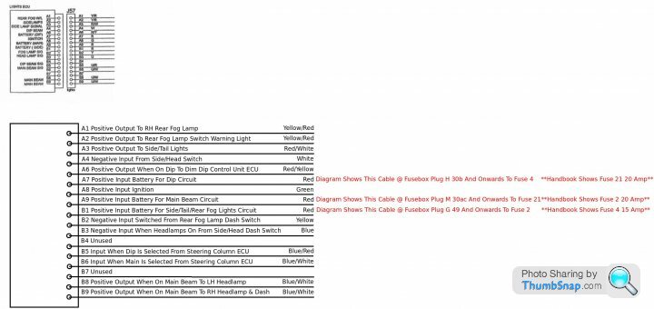
2.1 Lights ECU (J57)
A1 - Rear Fog W/L (Y/R)
A2 - Rear Fog W/L (Y/R)
A3 - Sidelamps (R/W)
A4 - Side Lamp Signal (W)
-
A6 - Dip Beam (R/Y)
A7 - Battery (Dip) (R)
A8 - Ignition (G)
A9 - Battery (Main) (R)
B1 - Battery (Side) (R)
B2 - Fog Lamp Sig (Y)
B3 - Head Lamp Sig (U)
B4 - N/C
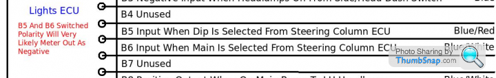
B5 - Dip Beam Sig (U/R)
B6 - Main Beam Sig (U/W)
B7 - N/C
B8 - Main Beam (U/W)
B9 - Main Beam (U/W)
2.2 Dim Dip Control Unit - ECU (J43)
B5 - Dip Power (R/Y) [traced from 'Lights ECU']
B4 - Dip Beam Drive (U/R)
B3 - Dim Dip Input (R/B)
B2 - Earth (B)
B1 - Headlamps On (U/Y)
A5 - Main Beam Signal (U/W)
A4 - Ignition (R)
-
A2 - N/C
A1 - N/C
2.3 Dim Dip Unit - ECU (J44-A)
1 - Ignition (G) (Green)
2 - Head Lamps On (U/W) (Blue with White) [traced from 'Dim Dip Control Unit-ECU']
3 - Battery (R) (Red)
4 - Earth (B) (Black)
5 - Side Lamps (R/W) (Red with White)
6 - Dim Dip Output (R/B) (Red with Black) [traced from 'Dim Dip Control Unit-ECU']
3. Door Control - ECU
J47 -J48-
J46 J45
(J45) door ECU conn 1
A1 - RH Pin Switch (W/P)
A2 - Lock Switch (S/W)
A3 - RH Inner Switch (O/W)
A4 - LH Inner Switch (O/W)
-
A6 - LH Outer Switch (O)
A7 - RH Outer Switch (O)
A8 - Boot Switch (B/R)
A9 - N/C
B1 - LH Pin Switch (W/P)
B2 - RH Window Position (U/V)
B3 - Alarm Input (K)
B4 - LH Window Position ?
B5 - RH Window Down (Y/G)
B6 - LH Window Up (R/B)
B7 - LH Window Down (R/G)
B8 - RH Window Up (Y/B)
B9 - Road Speed (S)
(J46) door ECU conn 2
A1 - Earth (B)
A2 - N/C
-
A4 - Battery (R)
A5 - N/C
B1 - N/C
B2 - N/C
B3 - N/C
B4 - N/C
B5 - N/C
(J47) door ECU conn 3
A1 - Boot Lock Drive (R/V)
A2 - Battery (R)
-
A4 - Earth (B)
A5 - Battery (R)
B1 - Interior Lamp (P/R)
B2 - RH Lock Drive 1 (U/O)
B3 - RH Lock Drive 2 (U/G)
B4 - LH Lock Drive 1 (U/W)
B5 - LH Lock Drive 2 (U/V)
(J48) door ECU conn 4
[Front]
B1 B2 B3 B4 B5
A1 A2 -- A4 A5
A1 - Earth (B)
A2 - RH Window 1 (Y/B)
-
A4 - LH Window 1 (R/G)
A5 - Earth (B)
B1 - RH Window 2 (Y/G)
B2 - Battery (R)
B3 - LED Drive
B4 - Battery (R)
B5 - LH Window 2 (R/G)
4.1 Immobiliser - ECU (J54)
1 - Ignition (G)
2 - Battery (R)
3 - Earth (B)
4 - Ignition ECU (G)
5 - Ignition ECU (G)
6 - Earth (B)
7 - N/C
8 - Starter (W/R) [traced from Ignition ECU B5]
9 - N/C
10 - Starter (W/R)
11 - Fuel Pump (Y)
12 - Fuel Pump (Y)
4.2 Alarm - ECU (J36)
1 - N/C
2 - Door Pin (W/P)
3 - Boot/Bonnet (U/B)
4 - N/C
5 - Alarm State (K)
6 - Earth (B)
7 - N/C
8 - Ignition (G)
9 - LH Indicator (G/R)
10 - N/C
11 - Battery (R)
12 - RH Indicator (G/W)
4.3 Alarm Accessory (J37)
1 - Battery (R) [Alarm ECU 11]
2 - Ignition (G) [Alarm ECU 8]
3 - Earth (B)
4 - Alarm State (K) [traced from Alarm ECU 5]
5 - Door Pin (W/P) [traced from Alarm ECU 2]
6 - N/C
Note: 5 - Door Pin connects to -> diode D1 / diode D2 -> LH Pin Switch [Door Control ECU B1] / RH Pin Switch [Door Control ECU A1] -> J33 [Pin1] / J33 [Pin 7]
5. Ignition ECU (J53)
A1 - Battery (IGN?) (R)
A2 - Ignition Earth (B)
-
A4 - N/C
A5 - Battery (Start) (R)
B1 - Ignition Output (W)
B2 - Start Signal (R/W)
B3 - Stop Signal (?)
B4 - N/C
B5 - Starter Drive (W/?) [Immobiliser ECU 8]
Colour Codes
B - Black
N - Brown
R - Red
O - Orange
Y - Yellow
G - Green
LTG - Light Green
U - Blue
P - Purple
K - Pink
W - White
S - Slate (Grey)
Edited by Juddder on Tuesday 23 November 11:32
Penelope Stopit said:
Updating
Interesting and yes I just double checked A7 the Dim Dip feed and it does indeed go through Fuse 4 according to the wiring diagrams, when the handbook fuse diagram says Fuse 21!So basically
Fuse 21 description = Fuse 4
Fuse 2 description = Fuse 21
Fuse 4 description = Fuse 2
Trace of Fuse 4 below
30b CON-H - J75 (pin 1) - Fuse 4 [along with CON-F - J73 (pin 1)] F 30AL (5 up) -> "Dim Dip Unit" - ECU pin 3 battery
Juddder said:
Penelope Stopit said:
Updating
Interesting and yes I just double checked A7 the Dim Dip feed and it does indeed go through Fuse 4 according to the wiring diagrams, when the handbook fuse diagram says Fuse 21!So basically
Fuse 21 description = Fuse 4
Fuse 2 description = Fuse 21
Fuse 4 description = Fuse 2
Trace of Fuse 4 below
30b CON-H - J75 (pin 1) - Fuse 4 [along with CON-F - J73 (pin 1)] F 30AL (5 up) -> "Dim Dip Unit" - ECU pin 3 battery
Wasn't going to bother looking at the Dim Dip Unit ECU wiring as it will all be redundant if doing away with the 3 ECUs
Couldn't resist looking after viewing your findings which do seem to prove the handbook wrong rather than the diagrams
When posting a step by step lighting circuit modification to https://www.pistonheads.com/gassing/topic.asp?h=0&... in the near future.......
Step 1 will be to verify which fuses are protecting each red cable
Updating
Have now added the Red/Yellow cable from Lights ECU to Dim Dip Control Unit ECU
This cable is important, it supplies 12 (give or take a little) volts positive to the Dip Beam Bulbs via the Dim Dip Control Unit ECU to
give full brightness dip beams. When the dim dip circuit is operating, a lower voltage is switched from the Dim Dip Unit ECU to the Dim
Dip Control Unit ECU, through it and onwards to the Dip Beam Bulbs
This tells us that the correct method for removing Dim Dip is to throw away the Dim Dip Control Unit ECU and Dim Dip Unit ECU then
join the Red/Yellow cable to the Blue/Red cable at the Dim Dip Control Unit ECU plug
Have now added the Red/Yellow cable from Lights ECU to Dim Dip Control Unit ECU
This cable is important, it supplies 12 (give or take a little
) volts positive to the Dip Beam Bulbs via the Dim Dip Control Unit ECU to give full brightness dip beams. When the dim dip circuit is operating, a lower voltage is switched from the Dim Dip Unit ECU to the Dim
Dip Control Unit ECU, through it and onwards to the Dip Beam Bulbs
This tells us that the correct method for removing Dim Dip is to throw away the Dim Dip Control Unit ECU and Dim Dip Unit ECU then
join the Red/Yellow cable to the Blue/Red cable at the Dim Dip Control Unit ECU plug
Edited by Penelope Stopit on Wednesday 24th November 18:11
Penelope Stopit said:
This tells us that the correct method for removing Dim Dip is to throw away the Dim Dip Control Unit ECU and Dim Dip Unit ECU then
join the Red/Yellow cable to the Blue/Red cable at the Dim Dip Control Unit ECU plug
Funnily enough I just wrote myself this note on the control box wiring list I am compiling based on two other posts for bypassing the Dim Dip effectjoin the Red/Yellow cable to the Blue/Red cable at the Dim Dip Control Unit ECU plug
Note: There are multiple ways to disable the Dim Dip Control Unit (called the DIM/DIP Switching Unit [ME0161] on the box), either cut wire B3 (the Dim Dip Input) or bridge a diode between A5 (Main Beam Signal) in the direction of B5 (Dip Power) so that 12V is supplied rather than the dipped 9.6V or so
Based on two posts by alinton here and here
Removing the boxes and joining a wire is a much nicer and more maintainable approach
There's also this good post about using the boot relay high current as the low current switch for new relays in the bonnet which is an OK approach too
Edited by Juddder on Wednesday 24th November 18:44
Edited by Juddder on Wednesday 24th November 18:51
Juddder said:
Penelope Stopit said:
This tells us that the correct method for removing Dim Dip is to throw away the Dim Dip Control Unit ECU and Dim Dip Unit ECU then
join the Red/Yellow cable to the Blue/Red cable at the Dim Dip Control Unit ECU plug
Funnily enough I just wrote myself this note on the control box wiring list I am compiling based on two other posts for bypassing the Dim Dip effectjoin the Red/Yellow cable to the Blue/Red cable at the Dim Dip Control Unit ECU plug
Removing the boxes and joining a wire is a much nicer and more maintainable approach
Edited by Penelope Stopit on Thursday 25th November 10:39
[Additional references added to Dim Dip bypass and a bit of formatting]
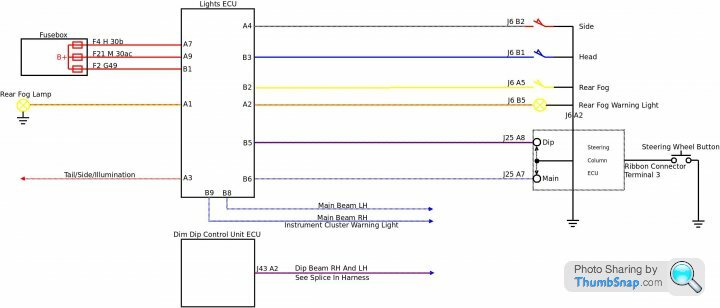
The Red/Yellow cable [B5 - Dip Power] connected to the Dim Dip Control Unit ECU is important as it supplies +12V (give or take a little) to the Dip Beam Bulbs via the Dim Dip Control Unit ECU to give full brightness dip beams.
When the dim dip circuit is operating, a lower voltage is switched from the Dim Dip Unit ECU to the Dim Dip Control Unit ECU, through it and onwards to the Dip Beam Bulbs
This tells us that the correct method for removing Dim Dip is to throw away the Dim Dip Control Unit ECU and Dim Dip Unit ECU then join the Red/Yellow cable [B5 - Dip Power] to the Blue/Red cable [B4 - Dip Beam Drive] at the Dim Dip Control Unit ECU plug (J43)
Received Durite Latching Relay specification this morning, wanted to use steering wheel Dip/Main Button to drive it and use its contacts to flip flop dip/main beams. Current consumption of relay is 0.96 Amps, steering wheel FFC ribbon will likely cope with 0.5 Amps max
Moving on
Now that the circuit has been well and truly broken down by thee and me, it has been proven to be far less complicated than it at first glance looks
The Durite Latching Relay would only need be used if there was a steering column ECU failure
Edited out some of this post due to a change of circuit
Edited by Penelope Stopit on Friday 26th November 17:24
Edited by Penelope Stopit on Saturday 27th November 09:30
Juddder said:
Additional references added to Dim Dip bypass and a bit of formatting
The Red/Yellow cable [B5 - Dip Power] connected to the Dim Dip Control Unit ECU is important as it supplies +12V (give or take a little) to the Dip Beam Bulbs via the Dim Dip Control Unit ECU to give full brightness dip beams.
When the dim dip circuit is operating, a lower voltage is switched from the Dim Dip Unit ECU to the Dim Dip Control Unit ECU, through it and onwards to the Dip Beam Bulbs
This tells us that the correct method for removing Dim Dip is to throw away the Dim Dip Control Unit ECU and Dim Dip Unit ECU then join the Red/Yellow cable [B5 - Dip Power] to the Blue/Red cable [B4 - Dip Beam Drive] at the Dim Dip Control Unit ECU plug (J43)
Purely out of interestThe Red/Yellow cable [B5 - Dip Power] connected to the Dim Dip Control Unit ECU is important as it supplies +12V (give or take a little) to the Dip Beam Bulbs via the Dim Dip Control Unit ECU to give full brightness dip beams.
When the dim dip circuit is operating, a lower voltage is switched from the Dim Dip Unit ECU to the Dim Dip Control Unit ECU, through it and onwards to the Dip Beam Bulbs
This tells us that the correct method for removing Dim Dip is to throw away the Dim Dip Control Unit ECU and Dim Dip Unit ECU then join the Red/Yellow cable [B5 - Dip Power] to the Blue/Red cable [B4 - Dip Beam Drive] at the Dim Dip Control Unit ECU plug (J43)
Are you sure the above is correct?
I've been using plug aperture numbers taken from diagrams for drawing diagrams
Perhaps the diagrams you're using are different to what I have access to
There is surely something incorrect with the following Dim Dip Control Unit ECU diagram, the ECU and plug numbers should surely be the same
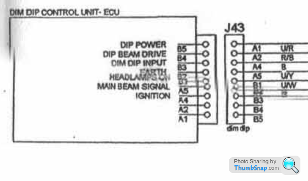
Should
Red/Yellow cable [B5 - Dip Power] to the Blue/Red cable [B4 - Dip Beam Drive] at the Dim Dip Control Unit ECU plug
Read
Red/Yellow cable [J43 A1 - Dip Power] to the Blue/Red cable [J43 A2 - Dip Beam Drive] at the Dim Dip Control Unit ECU plug
Or
Is plug J43 numbered incorrectly? I doubt it very much as every other ECU plug I've viewed is numbered starting with A Pins at the top and B Pins at the bottom
Gassing Station | Cerbera | Top of Page | What's New | My Stuff