Half the car is dead :-(
Discussion


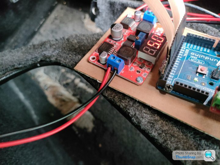
So the test hardware arrived and I'm still away from my car, but hopefully from the video below you can see the idea of what I'm trying to do for the Door Control ECU replacement
Relay 1 = Door Unlock
Relay 2 = Door Latch
Relay 3 = Window Down
Basically I'm trying to emulated the existing behaviour where it unlocks the door, drops the window for x amount of seconds, pulses the door latch and then re-enables the lock after y amount of time (*this may not be necessary and / or correct)
...and just to give a size comparison of how small these boxes are - we can easily use one for each door if we need to (*remember kids, smoking kills!)
Edited by Juddder on Monday 10th January 18:55
Door Control - ECU investigation: Day 3
So it's cold and miserable outside and I couldn't be asked to stand around in the cold outside testing with the car, so I put the Door Control ECU on the kitchen side and did some more investigations using a 12V switching power supply
With power connected to J46 (the power for the TTL logic board) and J47 (the power for the door lock relays and the boot lock relay) I can simulate the behaviour of when the Door ECU is powered on by the car
When this happens the first thing it does is apply power to the 4 door lock relays on pins B2, B3, B4 and B5. You can audibly hear them fire as I turn the power on and off below, and measuring between their pins and grounds gives +12V whereas other pins such as A1 [boot lock] and B1 [interior light] and all 0V (GND)

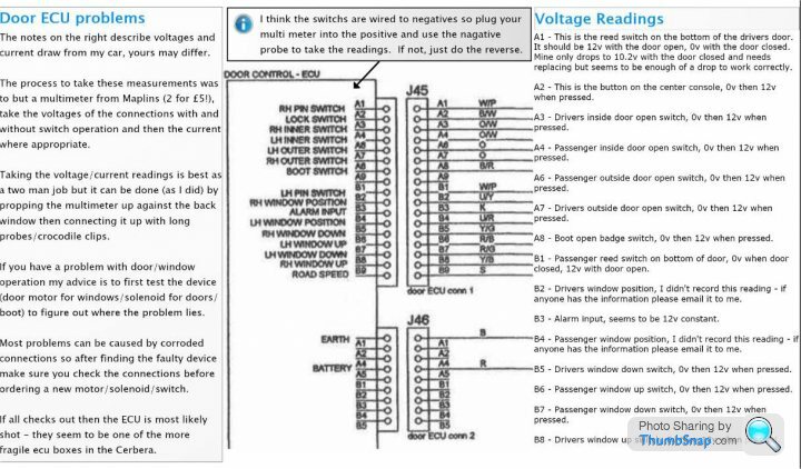
My strategy was to pick a very simple circuit to try and test the Door ECU activation with, and probably the simplest on the whole car is the boot button circuit, as it is actually away from the rest of the mess in the front and is just a simple switch in the boot
If you look at the circuit diagrams as to how this is triggered, by default it is floating, and probably pulled to high (+5V) using a pull-up resistor or similar
When the switch is pressed it is connected to GND and the value of that pin should drop to 0V

Trying this using a jumper lead between connector J45 -> pin A8 and GND results in no obvious relay switching so I am wondering if it is tied to the alarm in some way
Tracing J45 -> pin B3 on the Circuit Diagram connects it to the Alarm ECU J36 on pin 5 which is the Alarm State.

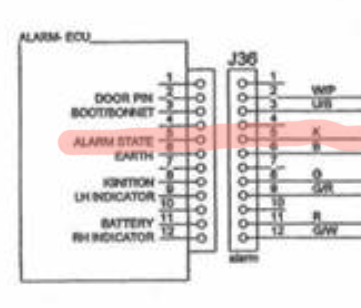
My logic is that if I can either pull this to GND or to +5V like other TTL true or false values I should be able to simulate disabling the alarm, and thus when I then simulate the boot switch being pressed by pulling that to GND is should trigger J37 -> pin A1 which is the BOOT LOCK DRIVE
Does anyone know what this value is by default and which way around it goes when the alarm is disabled?
So it's cold and miserable outside and I couldn't be asked to stand around in the cold outside testing with the car, so I put the Door Control ECU on the kitchen side and did some more investigations using a 12V switching power supply
With power connected to J46 (the power for the TTL logic board) and J47 (the power for the door lock relays and the boot lock relay) I can simulate the behaviour of when the Door ECU is powered on by the car
When this happens the first thing it does is apply power to the 4 door lock relays on pins B2, B3, B4 and B5. You can audibly hear them fire as I turn the power on and off below, and measuring between their pins and grounds gives +12V whereas other pins such as A1 [boot lock] and B1 [interior light] and all 0V (GND)
My strategy was to pick a very simple circuit to try and test the Door ECU activation with, and probably the simplest on the whole car is the boot button circuit, as it is actually away from the rest of the mess in the front and is just a simple switch in the boot
If you look at the circuit diagrams as to how this is triggered, by default it is floating, and probably pulled to high (+5V) using a pull-up resistor or similar
When the switch is pressed it is connected to GND and the value of that pin should drop to 0V
Trying this using a jumper lead between connector J45 -> pin A8 and GND results in no obvious relay switching so I am wondering if it is tied to the alarm in some way
Tracing J45 -> pin B3 on the Circuit Diagram connects it to the Alarm ECU J36 on pin 5 which is the Alarm State.
My logic is that if I can either pull this to GND or to +5V like other TTL true or false values I should be able to simulate disabling the alarm, and thus when I then simulate the boot switch being pressed by pulling that to GND is should trigger J37 -> pin A1 which is the BOOT LOCK DRIVE
Does anyone know what this value is by default and which way around it goes when the alarm is disabled?
DuncanM said:
I wouldn't wish the electronic failures on anyone, but in the nicest possible way, if they did have to happen to someone, Alex is the perfect chap to work through the issues. Could end up being amazing for us fellow owners 
Ha! Thanks Duncan Truthfully I'd wish it not to happen for anyone as it really is a pain in the hearse but hey as you say if it is going to happen to anyone, more handy if you have some vague idea what you are doing in this area Penelope Stopit said:
Found here https://www.pistonheads.com/gassing/topic.asp?h=0&...
verify that the Pink is low when the alarm is unarmed
Oh that's handy and funnily enough I've just gone out and tested exactly the same!verify that the Pink is low when the alarm is unarmed
I multi-metered between J45 pin B3 - Alarm Input (K) and J46 pin A1 - Earth (B) and can verify that when the alarm is disabled there is a 0V current on the Alarm Input.

As the alarm turns back on this raises to ~ +9V (guessing a low +12V)
I'm guessing from my testing yesterday that as the pin wasn't connected the relays turn on as if the car is alarmed as the input was floating. I'll try grounding it and see what those relays then do.
Also rhetorical question but does this mean that there is a constant 12V to each of these four relays when the alarm is enabled, in another words all of the time the car is parked? If so that will slowly be one of the things draining the battery...
Steering Wheel Functions Control Unit investigation: Day 1
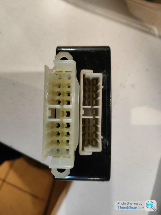
First thing first with this board was to mark up all of the pins and see if we can do anything with our initial investigation as it looks due to the burn damage that it's going to be difficult to repair so we might need to replace it too.
A couple of interesting observations:
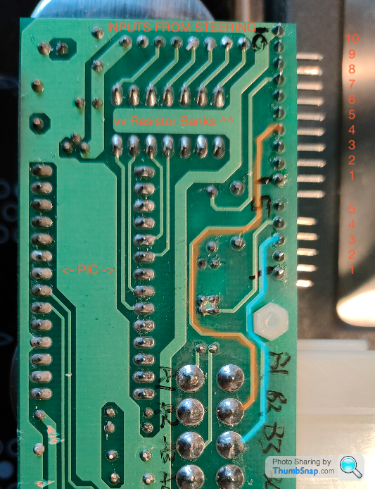
- The HAZARD SWITCH (5 pin connector pin 3 in Blue) and the HORN INPUT (10 pin connector pin 4 in Orange) go straight through to the harness connector bypassing any electronics
- All of the other steering wheel inputs are fed into resistor banks for pull-up(?) to +5V for logic 1 by default and then into the PIC for actioning as when the buttons are closed they connect to GND to give logic 0
So as with the other boards first thing first is to record all of the inputs and outputs:
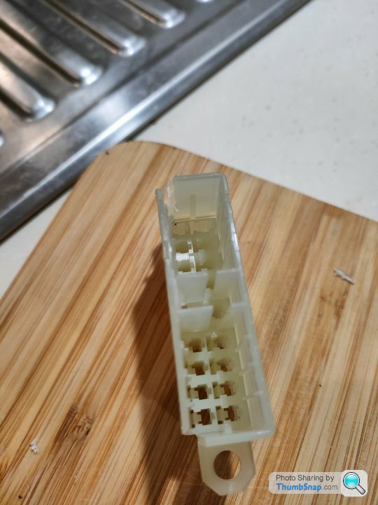
The 5 pin and 10 pin ribbon connectors aren't keyed so we need to find out which way around the connectors will go else we have a good chance of blowing up our board / Arduino when we reconnect it as +12V is on pin 7 which could be pin 3 if we connect it the wrong way around!
Looking at the wiring diagram, the only GND is pin 10 on the 10 pin ribbon connector, but as it's not keyed we don't know whether that is with the silver contacts facing up, or facing down
So I had a cunning plan which is to connect some long pins to the 10 pin connector, put the meter in continuity mode and then test with one of the switches on the steering wheel and GND
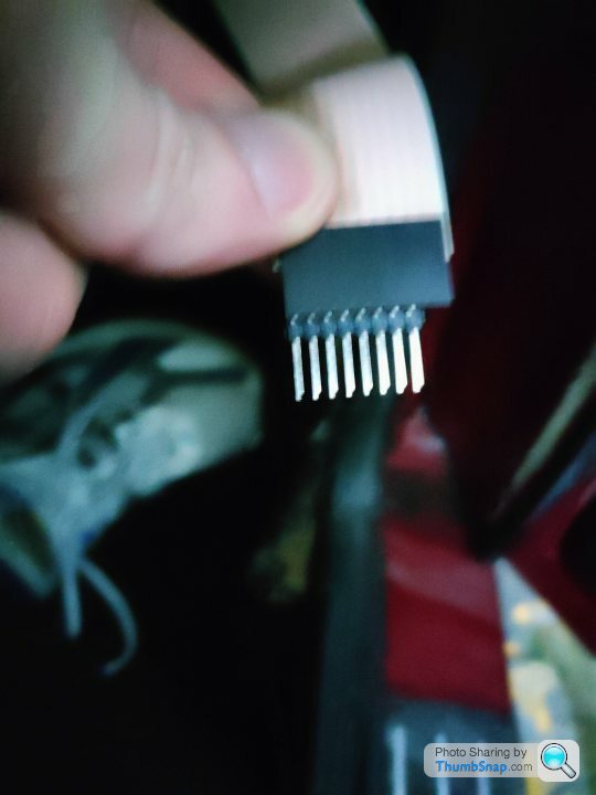
The Wiper Input looks like a good one to go for as it is pin 1 on the connector. Here's it being tested so at least we know which way around we need these ribbons for our board (the beep is what happens from the multimeter when connection is made)
My thoughts are that the role of the PIC is to take the indicator cancel signal from the steering wheel column mounted optical sensors and decide whether to cancel the indicators or not. If so we can easily emulate that with an Arduino and the spacing on the pins is the same so we can piggy back the existing ribbon connectors directly to our Arduino
Does anyone know what manufacture would have made these plugs and sockets because if I can find some matching ones we can probably pretty easily make an Arduino shield that we can solder this to and mount the Arduino on top
BTW one of the brokers quoted me £200 quid for one of these units and that was even if they had one, so making our own seems like a nice option for everyone if they need one in the future
First thing first with this board was to mark up all of the pins and see if we can do anything with our initial investigation as it looks due to the burn damage that it's going to be difficult to repair so we might need to replace it too.
A couple of interesting observations:
- The HAZARD SWITCH (5 pin connector pin 3 in Blue) and the HORN INPUT (10 pin connector pin 4 in Orange) go straight through to the harness connector bypassing any electronics
- All of the other steering wheel inputs are fed into resistor banks for pull-up(?) to +5V for logic 1 by default and then into the PIC for actioning as when the buttons are closed they connect to GND to give logic 0
So as with the other boards first thing first is to record all of the inputs and outputs:
Steering Wheel Functions Control Unit

A1 - N/C
A2 - HEADLAMP SIGNAL
A3 - N/C
A4 - N/C

A6 - WIPER 2 SIGNAL
A7 - MAIN BEAM SIGNAL
A8 - DIP BEAM SIGNAL
A9 - TURN LEFT SIGNAL

B1 - IGNITION
B2 - HORN DRIVE
B3 - HAZARD DRIVE
B4 - BATTERY
B5 - GND
B6 - WIPER 1 SIGNAL
B7 - N/C
B8 - WASHER SIGNAL
B9 - TURN RIGHT SIGNAL

10 Pin Ribbon

10 - GND
9 - CANCEL RHT IP
8 - CANCEL LEFT IP
7 - +12V
6 - N/C
5 - N/C
4 - HORN INPUT
3 - DIP / MAIN
2 - WASHER INPUT
1 - WIPER INPUT

5 Pin Ribbon

5 - N/C
4 - HAZARD W/L
3 - HAZARD SWITCH
2 - INDICATOR RIGHT
1 - INDICATOR LEFT
The 5 pin and 10 pin ribbon connectors aren't keyed so we need to find out which way around the connectors will go else we have a good chance of blowing up our board / Arduino when we reconnect it as +12V is on pin 7 which could be pin 3 if we connect it the wrong way around!
Looking at the wiring diagram, the only GND is pin 10 on the 10 pin ribbon connector, but as it's not keyed we don't know whether that is with the silver contacts facing up, or facing down
So I had a cunning plan which is to connect some long pins to the 10 pin connector, put the meter in continuity mode and then test with one of the switches on the steering wheel and GND
The Wiper Input looks like a good one to go for as it is pin 1 on the connector. Here's it being tested so at least we know which way around we need these ribbons for our board (the beep is what happens from the multimeter when connection is made)
My thoughts are that the role of the PIC is to take the indicator cancel signal from the steering wheel column mounted optical sensors and decide whether to cancel the indicators or not. If so we can easily emulate that with an Arduino and the spacing on the pins is the same so we can piggy back the existing ribbon connectors directly to our Arduino
Does anyone know what manufacture would have made these plugs and sockets because if I can find some matching ones we can probably pretty easily make an Arduino shield that we can solder this to and mount the Arduino on top
BTW one of the brokers quoted me £200 quid for one of these units and that was even if they had one, so making our own seems like a nice option for everyone if they need one in the future
Edited by Juddder on Sunday 16th January 18:05
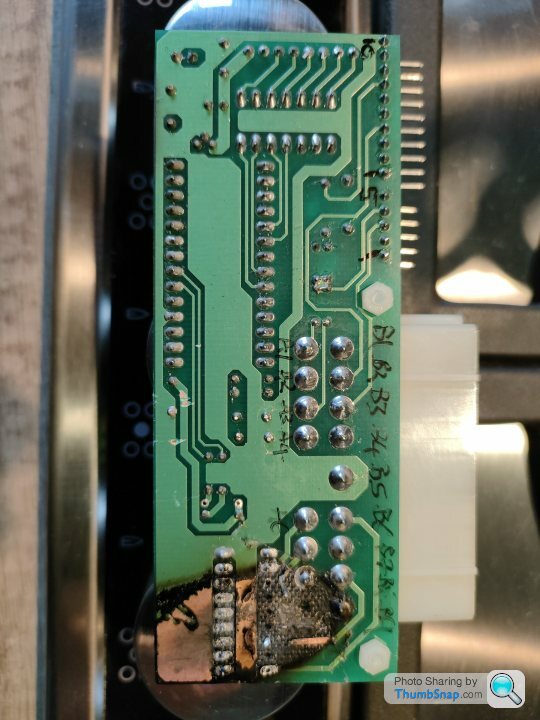
One other note for my own analysis is that the wiring diagram has A1 and A3 as N/C (Not Connected) but as you can see in the photos below there are definitely connections on there (in Orange) as we know that A1 is the middle pin as that is labelled on the top of the board and A is keyed
Bottom:

Top:

Wiring Diagram:

Bottom:
Top:
Wiring Diagram:
Steering Wheel Functions Control Unit investigation: Day 2
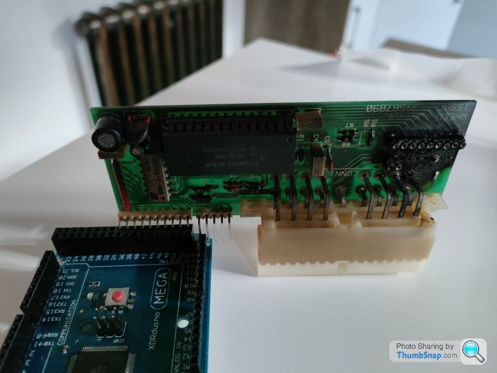
So they say a picture says a 1,000 words (or something like that) so here's two pictures and a couple of videos of my replacement Steering Wheel Functions Control Unit Arduino.


Thing to note for others in the future is that the all black side of the ribbon connectors is the top, and the side that shows the silver pins through windows is the bottom - might not be the same for everyone but seems logical
So they say a picture says a 1,000 words (or something like that) so here's two pictures and a couple of videos of my replacement Steering Wheel Functions Control Unit Arduino.
Thing to note for others in the future is that the all black side of the ribbon connectors is the top, and the side that shows the silver pins through windows is the bottom - might not be the same for everyone but seems logical
FarmyardPants said:
Brilliant progress! Is it event driven or do you have to poll the inputs? I've not worked with Arduinos before.
The Arduino basically runs in an infinite loop and you just pole the buttons every iteration to check for changes - I'm also using the Bounce2 de-bounce library to ensure that we get clean presses of the buttons, rather than noiseI've put the source code as is today up on my GitHub account and here's the bounce library for a bit of reference
This week I've been studying the indicator cancellation PCB as this is an interesting bit of kit, using two optical switches much like the optical spinners of 1980's arcade games such as Tron and Tempest
In the original SWFCU +12V is supplied on pin 7 of the 10 pin ribbon connector and then the two outputs of the optical switches fed back to the unit on pins 8 and pins 9 (with GND on pin 10 to complete the circuit)
As the Arduino is +5V not +12V I've added some test code to put pin 7 into Output mode and pull it HIGH (=+5V) and to put pin 10 into Input mode and pull it LOW (=GND).
So far this code is written blind, but in theory and from reading quite a few slotted optical switches datasheets many of them support +5V as well as +12V so we might be lucky and be able to power them this way
The slotted disc on the steering wheel (I'm theorising) goes through the corresponding optical switch as you turn the wheel in the direction that you are indicating, and then we need to track it coming back through the same optical switch as this will in effect be the cancelation effect we want to trigger
I think the only way I'm going to be able to really test this is jack up both sides of the front and then run in debug with the steering wheel and do multiple turns of the wheel etc to monitor the output of these optical switches. I've also put the code into Digital mode as, in theory, they should either be open or closed, but we can run them as Analogue inputs if we need to and look for a threshold change to indicate the open / close state
For a short term solution I'm going to add some code that has a second trigger of each indicator to act as the cancel - this way you can indicate, turn the car and then bounce the indicator again to cancel the event - not perfect but means I can drive and indicate
Finally here's some good images that I borrowed from this thread and this thread which show the board and it's connectors
From the bottom photo you can see the 4 pin connector that comes in from the indicator stalk, and the 3 pin connector that comes in from the hazard switch. These are simply passed through to the 5 way ribbon cable, but the PCB acts as a junction for all of the connectors to meet and travel down to the SWFCU
The PCB is also pretty well labelled and you can see the input resistors and diodes, as well as the output resistors and the connection from the WHEEL and going to the ECU
Top
Bottom

Circuit Diagram
 ]
]PinOut
Indication Cancellation Sensor PCB

10 Pin Ribbon

10 - GND
9 - CANCEL RHT IP
8 - CANCEL LEFT IP
7 - +12V
6 - N/C
5 - N/C
4 - HORN INPUT
3 - DIP / MAIN
2 - WASHER INPUT
1 - WIPER INPUT

5 Pin Ribbon

5 - N/C
4 - HAZARD W/L
3 - HAZARD SWITCH
2 - INDICATOR RIGHT
1 - INDICATOR LEFT

3 Pin Connector

3 - RIGHT TURN (W)
2 - GND
1 - LEFT TURN (G)

4 Pin Connector

4 - N/C
3 - N/C
2 - GND
1 - HAZARD SWITCH
Steering Wheel ECU Replacement - Ongoing investigation
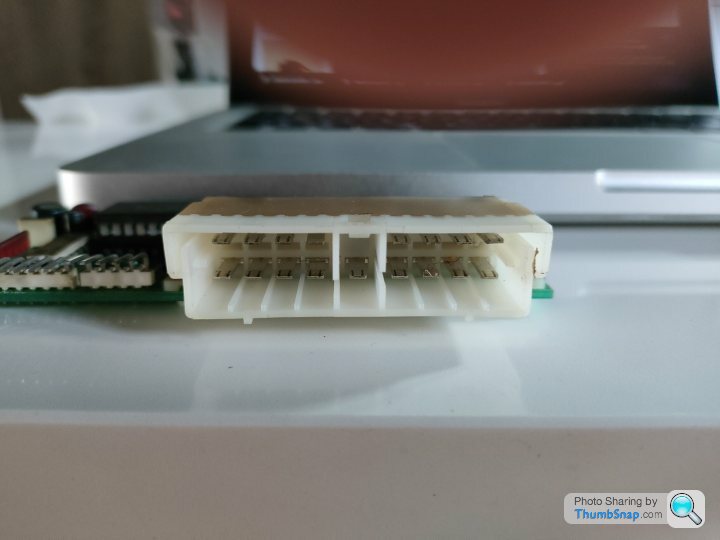
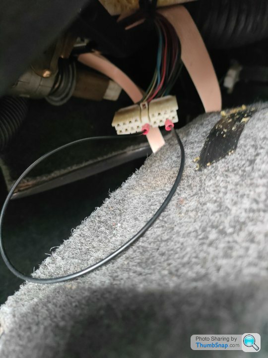
So for the output side of our Arduino replacement Steering Wheel ECU we need to match the socket on the original unit, so that the plug that is on the car already can be connected to it without having to either a. cut and rewrite all the wiring or b. take out the pins and try and rehouse them
Digging around through Google images using the original socket shot, I found these lovely people over at automotiveconnectors.com who identified the socket as a "17 Way TE Connectivity M.I.C Mark II Natural (.118) Female"
So I ordered some of these along with their matching pins however when I got them to the car there is a small problem...
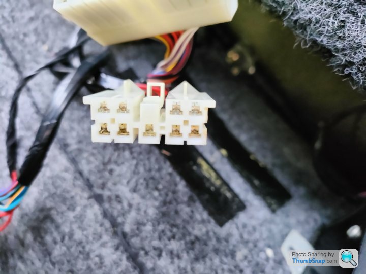
The sockets and plugs that TVR used are very very similar to the TE Connectivity ones however the TVR ones have an added 'wing' on the top sides of the plug and extra corners on the top sides of the socket. Here's a photo showing one of the plugs on the car
So I went back to the guys at automotiveconnectors.com to see if they stocked those, but they don't and I can't find them anywhere else, so I ended up with the cunning plan of let's get out a sharp craft knife and turn the new sockets into matching sockets for the original plugs
If you look at the photo the difference is the 'wings' and the two key elements in the middle are offset from each other in the originals, but not in the new ones
So here's the final new ones with extra cut outs for the wings versus the original
and with an extra bit removed to make the keys match
Now to do the wiring and the crimping and then we can actually test the new unit on the car
So for the output side of our Arduino replacement Steering Wheel ECU we need to match the socket on the original unit, so that the plug that is on the car already can be connected to it without having to either a. cut and rewrite all the wiring or b. take out the pins and try and rehouse them
Digging around through Google images using the original socket shot, I found these lovely people over at automotiveconnectors.com who identified the socket as a "17 Way TE Connectivity M.I.C Mark II Natural (.118) Female"
So I ordered some of these along with their matching pins however when I got them to the car there is a small problem...
The sockets and plugs that TVR used are very very similar to the TE Connectivity ones however the TVR ones have an added 'wing' on the top sides of the plug and extra corners on the top sides of the socket. Here's a photo showing one of the plugs on the car
So I went back to the guys at automotiveconnectors.com to see if they stocked those, but they don't and I can't find them anywhere else, so I ended up with the cunning plan of let's get out a sharp craft knife and turn the new sockets into matching sockets for the original plugs
If you look at the photo the difference is the 'wings' and the two key elements in the middle are offset from each other in the originals, but not in the new ones
So here's the final new ones with extra cut outs for the wings versus the original
and with an extra bit removed to make the keys match
Now to do the wiring and the crimping and then we can actually test the new unit on the car
Polly Grigora said:
Please have you any updates?
Sorry - I have - just been busy with other projects and didn't get a chance to update the thread!Steering Wheel ECU - On going replacement
So in order to drop the +12V Battery positive power supplied on B4 of the 18 pin connector we're going to use a buck/boost convertor as previously mentioned, but we need to tune it before connecting it to the Arduino so that we have the exact power level we want, even if the car is charging (+14V potentially) or just turned on (+12V) or running the starter motor (<+12V potentially)
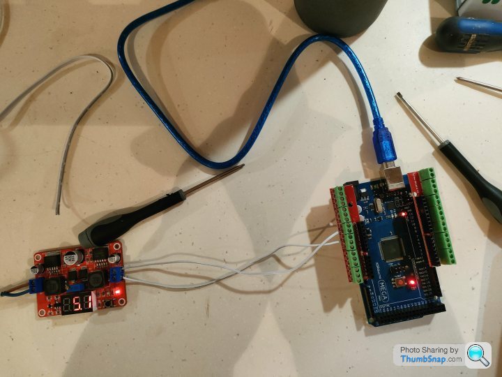
To do this I grabbed a 240V AC -> +12V / +5V DC linear power supply as used on modern arcade machines, and ran the +12V output into the bbc to see what the default output was
Out of the box it's boosting the voltage to around +27V as per this picture
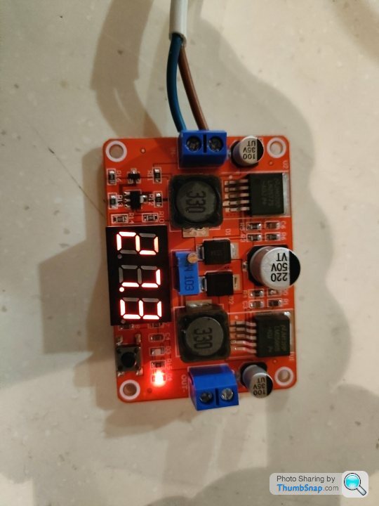
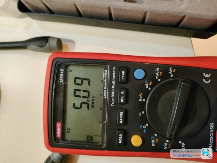
The bbcs have a little variable resistor on them which can be turned with a screwdriver to adjust the output voltage so first step is to drop this down to a steady +5.0V / +5.1V for cleanly feeding the Arduino
BTW just in case anyone is wondering why we don't use the fact that the Arduino Mega itself has a voltage regulation circuit itself that could reduce the +12V to +5V it's because it would produce a lot of heat and as we have this unit potentially powered up for a number of hours it's cleaner just to provide it with a clean power feed
Also bang/boost converters are super cheap so if that packs in we don't really care, where as Arduinos are more expensive ;-)

So now that we've got the unit powered let's have a think about how to case this as we want to dissipate heat and provide some protection for the unit
Luckily both of the units together have a pretty small form factor
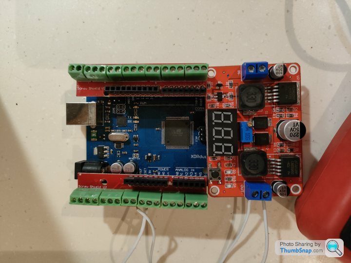
Because we're going to have our connectors coming in the top of the Arduino we need a super slim case so I found this one that allows access to the top pins but still gives a lot of protection

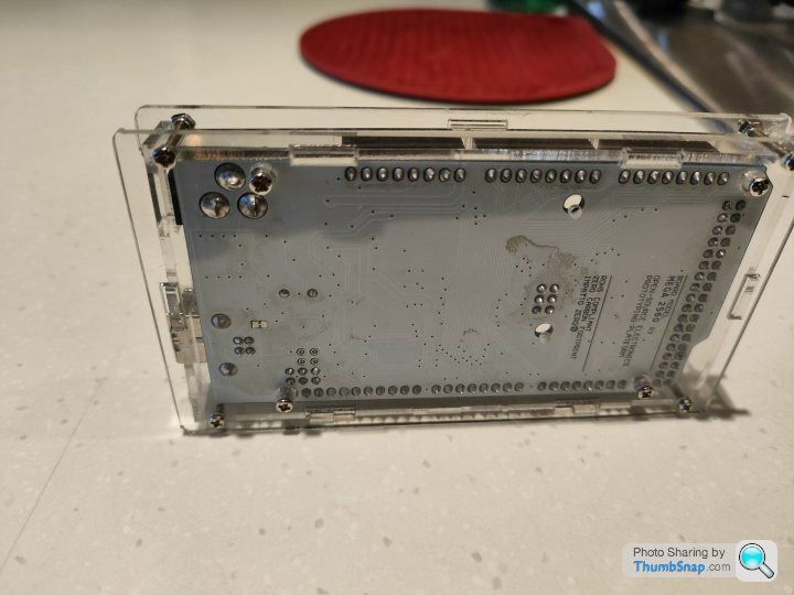
So let's put everything together, power it up with +12V and then after a final check we're ready to plug it into the car for initial live testing.
BTW I haven't crimped on the proper plug pins at this point as I'm going to test it with crimp pins and then just replace those once it's all working as expected

Next update in a couple of weeks when I'm back in the same location as my car
Polly Grigora said:
Update is much appreciated
Are you planning on connecting the steering switches Arduino outputs directly to the rear ECU?
No, not exactly - the steering wheel ECU does some clever stuff in between where it adds modes to the switches so for example pressing the wiper button once does a slow sweep by powering B6 - WIPER 1 SIGNAL and then a second press connects the output to A6 - WIPER 2 SIGNAL, and similar with the headlight button so my Arduino module needs to do the sameAre you planning on connecting the steering switches Arduino outputs directly to the rear ECU?
On update news I'm back with my car in London next week so will try it out for real
Edited by Juddder on Wednesday 16th March 11:37
Polly Grigora said:
Sorry, I didn't make that at all clear
Are you connecting the dip and main beam outputs directly from the Arduino directly to the lights ECU?
Ah, yes I think I get what you meanAre you connecting the dip and main beam outputs directly from the Arduino directly to the lights ECU?
Yes my plan was to have the Arduino outputs drive the rear other ECU inputs, such as the lights ECU, directly as the +5V high of the Arduino outputs should match the +5V output of the original TTL circuit as that wasn't using relays or anything like that to drive the inputs just direct from the +5V supply on the board with some resistor banks iirc
Anything I'm missing?

Ah - OK I get your point
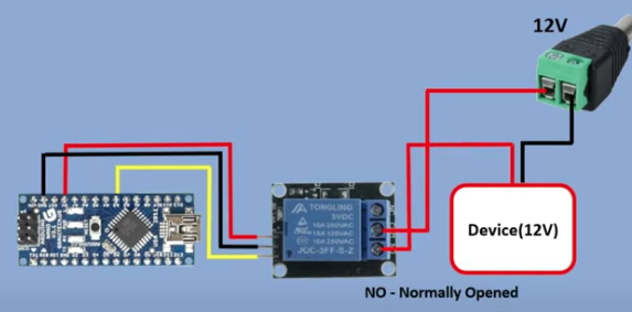
Basically that the 40 ma from the +5V output of the Arduino won't be enough to drive the +12V relays in the boot boxes from their datasheet, so we will need to use our own relays or transistors and the +12V power source instead of a direct connection as per this helpful video
I may therefore need to do a bit more fiddly wiring as we will need to link the +12V from the Steering Wheel Functions Control Unit pin B4 battery to each of the relays as a normally open circuit (NO) or transistors
Feels like designing a PCB to do this would be best, but for the moment I'm going to get some pinned low Amp Arduino relays as per the shot below and put one in-line to see if that works correctly
This is the same concept with a transistor which will require a PCB but work much more efficiently I think
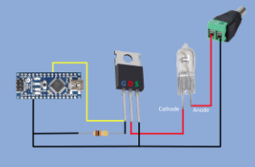
Both images from Mario's Ideas as linked above
Additional:
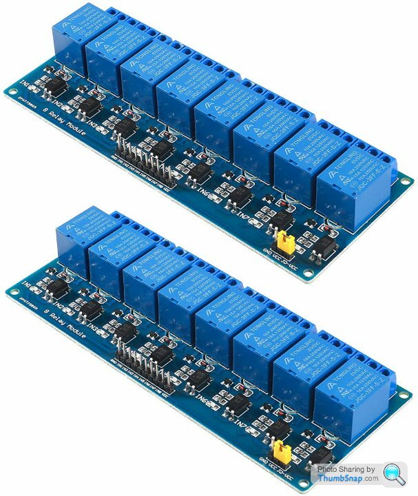
I think using one of these would do the trick as they have a low 5-20mA Driver Current and can easily cope with +12V on the relay side
Basically that the 40 ma from the +5V output of the Arduino won't be enough to drive the +12V relays in the boot boxes from their datasheet, so we will need to use our own relays or transistors and the +12V power source instead of a direct connection as per this helpful video
I may therefore need to do a bit more fiddly wiring as we will need to link the +12V from the Steering Wheel Functions Control Unit pin B4 battery to each of the relays as a normally open circuit (NO) or transistors
Feels like designing a PCB to do this would be best, but for the moment I'm going to get some pinned low Amp Arduino relays as per the shot below and put one in-line to see if that works correctly
This is the same concept with a transistor which will require a PCB but work much more efficiently I think
Both images from Mario's Ideas as linked above
Additional:
I think using one of these would do the trick as they have a low 5-20mA Driver Current and can easily cope with +12V on the relay side
Edited by Juddder on Thursday 17th March 16:21
TVR Cerbera Steering Wheel Functions Control Unit Emulator: Day quite-a-lot
I've been a bit quiet as I moved my car from London out to the country on a loader as a. there is literally no point anymore having a car like a TVR in London as the speed limit is now 20mph and you get fined every time you want to drive it and b. I can spend more time on it if it is nearer to where I am most of the time
So today I checked that the engine still starts, drives and works (which gratefully is does very well) and then put some finishing touches to the bench testing of my TVR Cerbera Steering Wheel Functions Control Unit Emulator
In the video below I'm connecting a test pin to pin 43 which I have setup as the horn input pin, and I've updated the behaviour for the horn and washer buttons so they are not latching buttons as per the rest, but are only active when pressed (which connects them to ground)
Testing pin 43 by connecting it to GND you can see that this then triggers the output pin 7 to LOW which drives the relay for the horn to power on and connect the two output pins of +12V on the car (not connected) to the horn drive pin which should then turn the horn on
Releasing the connection to GND let's the Arduino's internal pull-up resistor come into play and pull the current to +5V which drives the horn drive pin 7 to HIGH which turns the relay off again
Next step is to velcro the boards to the steering wheel undertray, connect it all to the output of the car and try the same test - if this works as planned I will be able to honk the horn, which means that making the rest work is easy from there
More updates when I get it together and start in-car testing!
TVR Cerbera Steering Wheel Functions Control Unit Emulator
Edited by Juddder on Sunday 10th April 19:30
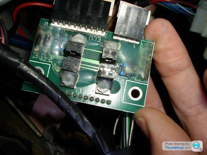
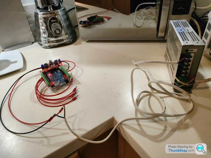
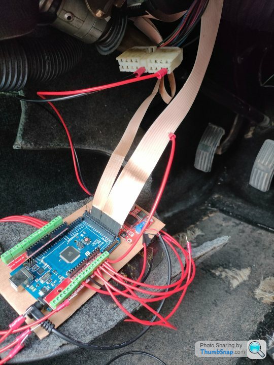
So a bit quiet on the updates but finally had some time to test out my prototype board today
The good news
All the power logic works and I can run everything happily off of the core wiring
The needs improvement news is that my thoughts were wrong on using digital logic to power the switches won't work as the outputs need either floating or ground to trigger / untrigger
Also the Arduino runs to ground when the board is powered off but connected to the power circuit so I will need relays in-between
Here's a couple of photos from the testing today

Jabbah said:
This is very cool. I've been wondering for a while if doing something like this would be possible.
Thanks - necessity was the mother of all invention in my case, but hey at least we should have replacement options going forwards Jabbah said:
Should be possible to fix the issue the window going up inside the A pillar trim when the door almost latches but doesn't.
The challenge we have here is that we have the same inputs and outputs as the original control boxes have, so nothing cleverer like being able to sense the amount of strain on the motor or whether the door latch is fully latched or lot. The mechanisms are actually quite simple in that they simply pulse the door latch release, drop the window and hope that you manage to open the door in timeThe same (in my head) happens with the boot lock solenoid where the software just pulses this three times to release the lock, and hopes that you open the boot in the time
Adding sensors that feedback whether it is open or not such as extra microswitches would be handy - that's the principal of the one that is used in the window position sensor microswitch in the doors. It's closed when the window is ~80% odd closed and then I imagine the software uses a timing loop to turn the motor off expecting it to have reached the top in that time
Jabbah said:
My heater control box is on the way out too and looks like someone else is already almost there with that.
Would be interested in that thread to see what they've used in their project - one thing I am looking for a more production ready version of these is to use a modern day microcontroller such as a Genie® or a PICAXE® and use it with an integrated relay board such as this one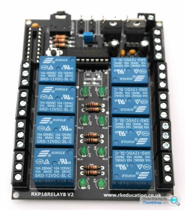
Jabbah said:
I'm thinking that we could add a simple timer and recheck of the reed switch:
- Close door
-- If reed switch activates
--- Wait for n seconds
--- If reed switch still indicates door is shut
Raise window
Going back through my notes I found this diagram which shows we actually have a - Close door
-- If reed switch activates
--- Wait for n seconds
--- If reed switch still indicates door is shut
Raise window
Therefore we can probably easily do as you suggest above as we can track the door
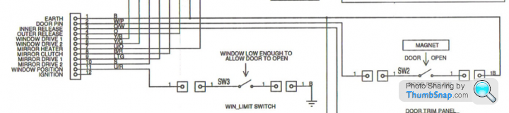
If you look at the original TVR wiring diagrams they use the window reed switch as an indicator that the window is low enough to open the door
Edited by Juddder on Monday 27th June 12:19
FarmyardPants said:
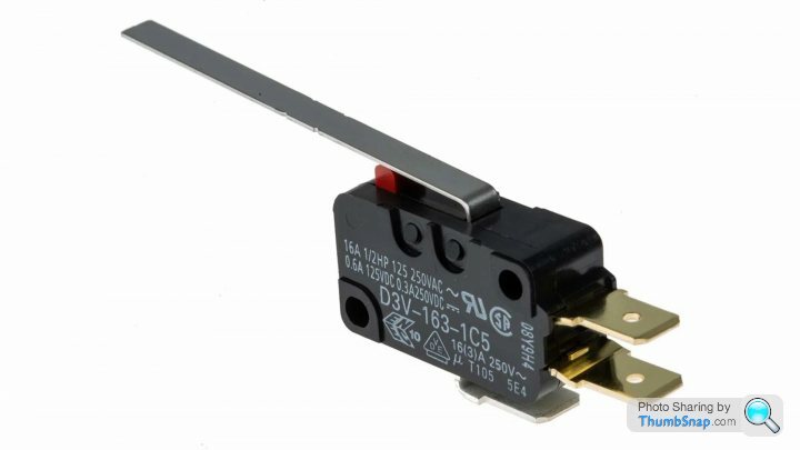
The window limit switch is a microswitch operated by the window
Yes - typing too fast too early in the morning The switch in the door for tracking whether the window is down or up is a microswitch with an extra long closer on it - the same as used in modern arcade joysticks
If I remember correctly from replacing the wiring harness in my drivers door it looks like this, but might have the contacts on the bottom
The bottom of the door switch has the magnet glued into the body of the car where the door closes - I didn't play with the switch actually in the bottom of the door, but good to hear that that can be moved if needed
Gassing Station | Cerbera | Top of Page | What's New | My Stuff