Half the car is dead :-(
Discussion


DuncanM said:
A question for Judder and Penelope:
Are the TVR ECUs that bad (generally, not just lights) ? If so, what reasons do you think TVR had for using them?
I'll answer this question about the Door Control Box as Penelope is much more informed about the lights and dim / dip boxes than I am Are the TVR ECUs that bad (generally, not just lights) ? If so, what reasons do you think TVR had for using them?

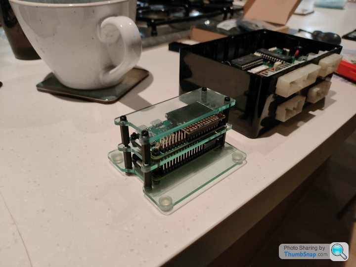
Looking at the Door Control Box yes it's actually pretty well made
TVR were pretty on the ball to use a "powerful (200 nanosecond instruction execution) yet easy-to-program (only 33 single-word instructions) FLASH-based 8-bit microcontroller" [*marketing blurb taken from Microchip who make the PIC] and they've actually made the boards pretty well with nice things such as sockets for the PICs to go into (*cheapskates just solder the chips straight to the PCB)
It just feels like they didn't expect people to be still maintaining them
I'll add an update post below about what I've been doing with the microcontrollers

Edited by Juddder on Sunday 5th December 18:46
Door Control - ECU investigation: Day 2
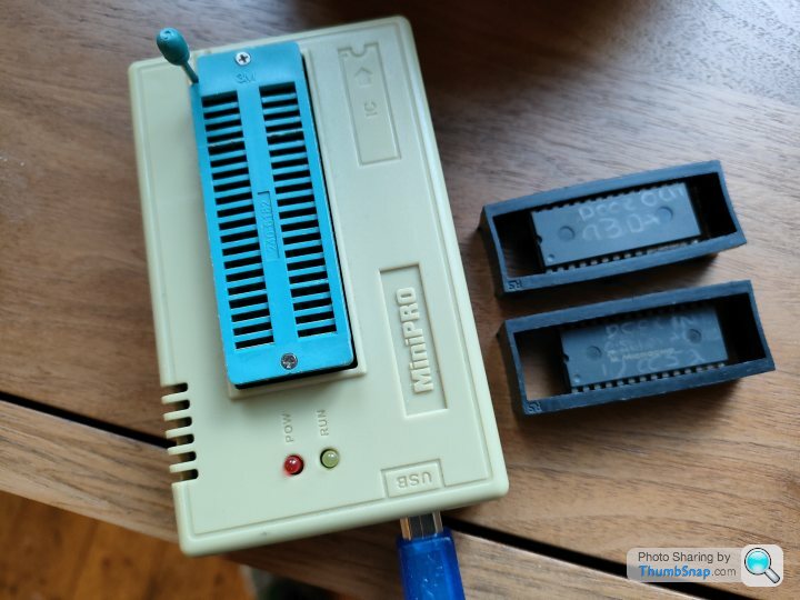
So in order to rule out the PIC16C57C chips from being the problem with the Door Control Box I read through the datasheet for my MiniPro EPROM reader and it turns out it can read the program from them to verify they are alive
Also, strangely a past version of me must have predicted this happening as I bought from eBay a few years ago two chips that were advertised as "ex-TVR factory Cerbera Door Control ECU chips" and stuck them in a drawer for a rainy day
Therefore as we now have two chips, we can use one as the comparison for the other, read them both and then verify the data read against the other one to validate that the chips are a. working and b. the same code
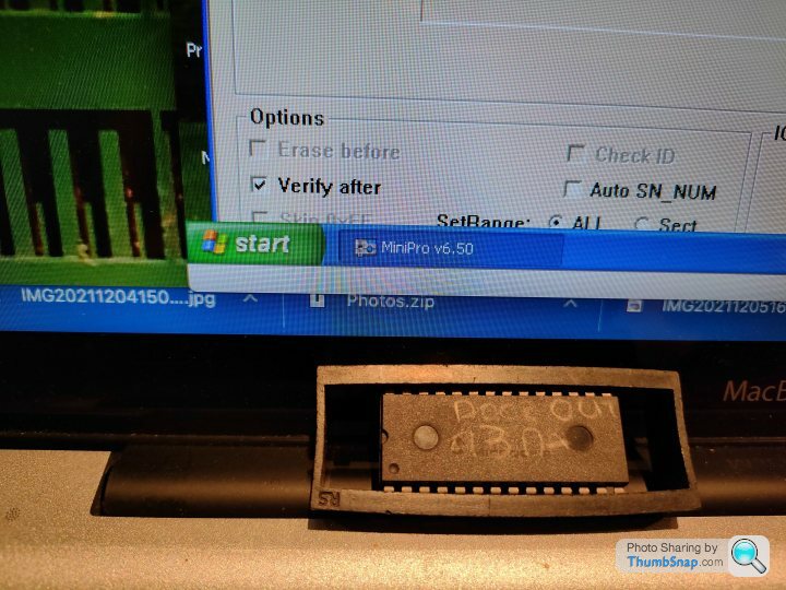
The miniPro software only runs on Windows so I'm running a VM of Windows on my Mac but as you can see from the screen shot below the verification of the first Door Out chip from my backup set versus the Door Out chip from the Door Control Box is verified as identical so it looks like they are actually fine
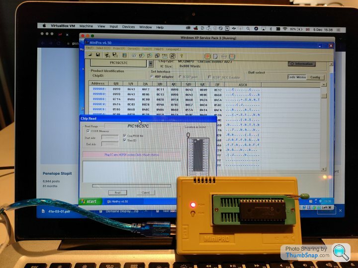
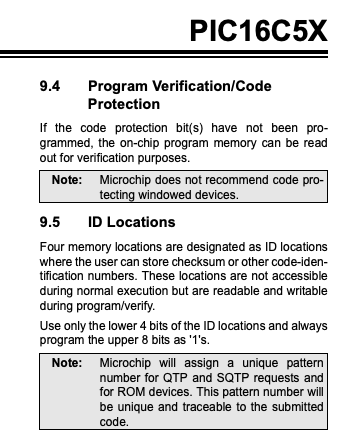
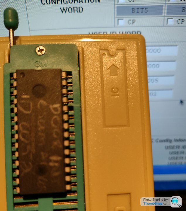
On the ex-factory chips the programmer had very helpfully written on the chip in pencil the checksum / user ID of the chip, which according to the datasheet are 4 programmable locations that are used to verify that what is written to the chip matches the original program code uploaded
On the Door Out chip this is 93DA and as you can see from the second shot below when I read the chip contents we can see an exactly matching number in the Used ID Word section of the chip read details. This proves that we've read the contents of the PIC correctly

Door In has "ID 0052" written on it and that matches the 4 User ID values when we read that one in too, so that's all good as well
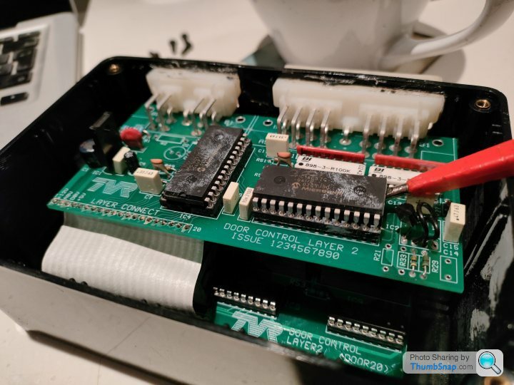
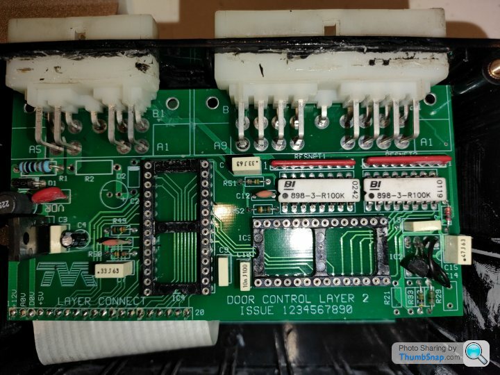
While I had the chips out I took some high resolution shots of the PCB layer as many of the traces are hidden under the chips when in situ so that I can trace which pins of the PICs are triggering the relays to open the door latch, drop the window etc and which pins are being used for the inputs such as the door open button etc.
My cunning plan if the Door Control ECU still refuses to come back to life with more investigation it to replace this top board with an Arduino or similar, and then write my own code to trigger / emulate the same sequences as the current PICs do with the relays for opening and closing the doors
So in order to rule out the PIC16C57C chips from being the problem with the Door Control Box I read through the datasheet for my MiniPro EPROM reader and it turns out it can read the program from them to verify they are alive
Also, strangely a past version of me must have predicted this happening as I bought from eBay a few years ago two chips that were advertised as "ex-TVR factory Cerbera Door Control ECU chips" and stuck them in a drawer for a rainy day
Therefore as we now have two chips, we can use one as the comparison for the other, read them both and then verify the data read against the other one to validate that the chips are a. working and b. the same code
The miniPro software only runs on Windows so I'm running a VM of Windows on my Mac but as you can see from the screen shot below the verification of the first Door Out chip from my backup set versus the Door Out chip from the Door Control Box is verified as identical so it looks like they are actually fine
On the ex-factory chips the programmer had very helpfully written on the chip in pencil the checksum / user ID of the chip, which according to the datasheet are 4 programmable locations that are used to verify that what is written to the chip matches the original program code uploaded
On the Door Out chip this is 93DA and as you can see from the second shot below when I read the chip contents we can see an exactly matching number in the Used ID Word section of the chip read details. This proves that we've read the contents of the PIC correctly
Door In has "ID 0052" written on it and that matches the 4 User ID values when we read that one in too, so that's all good as well
While I had the chips out I took some high resolution shots of the PCB layer as many of the traces are hidden under the chips when in situ so that I can trace which pins of the PICs are triggering the relays to open the door latch, drop the window etc and which pins are being used for the inputs such as the door open button etc.
My cunning plan if the Door Control ECU still refuses to come back to life with more investigation it to replace this top board with an Arduino or similar, and then write my own code to trigger / emulate the same sequences as the current PICs do with the relays for opening and closing the doors
Edited by Juddder on Sunday 5th December 17:09
Edited by Juddder on Sunday 5th December 19:49
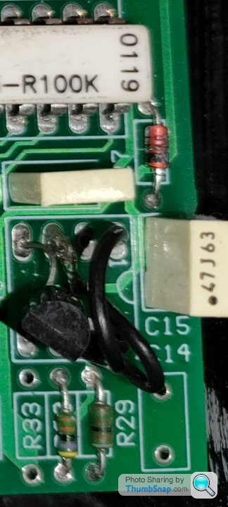
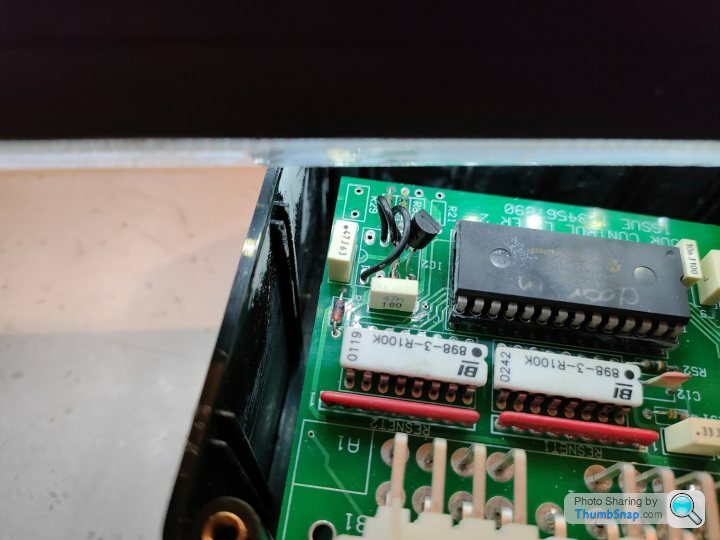
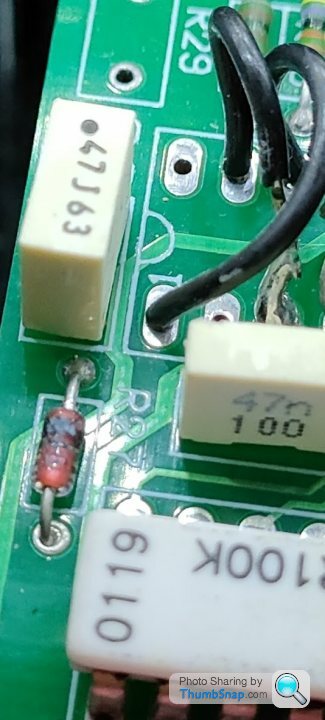
So while tracing out the pins to the IC4 which is the PIC that connects to the lower relay PCB I noticed this in the right hand corner of the board that looks very much like a blown resistor or diode
I've circled it in Orange below
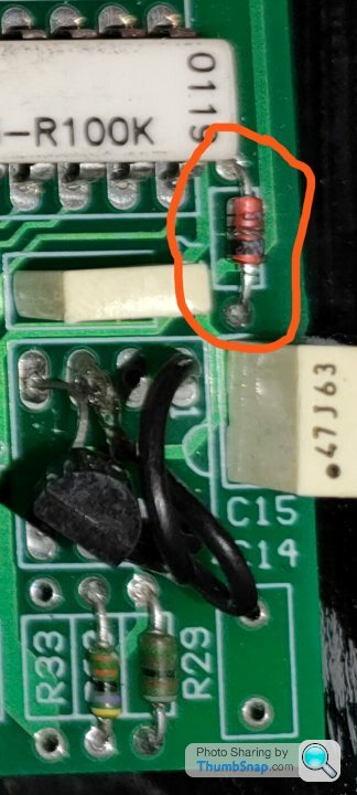
Hopefully the PCB designer was a good electronics citizen and put the value of what it is (I think it says R7 next to it from the shot so should be a resistor) underneath the component on the PCB so I will desolder it tomorrow and see what it says
@Penelope Do you know what the IC circled in blue was meant to be? Looks like they've bodged a transistor in there with some jumper wires instead (*note to post above about good board design - looks like they ran out of components so just did the same as the TTL chip would do with a transistor and some wires - not beautiful!)
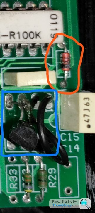
Note to anyone doing investigations like this - take lots of high res photos as you can study them and try and visually see where the problems are. When I initially opened the Door Control ECU it had that melted chip smell in there so I knew that it was highly likely something somewhere was blown on the board...
I've circled it in Orange below
Hopefully the PCB designer was a good electronics citizen and put the value of what it is (I think it says R7 next to it from the shot so should be a resistor) underneath the component on the PCB so I will desolder it tomorrow and see what it says
@Penelope Do you know what the IC circled in blue was meant to be? Looks like they've bodged a transistor in there with some jumper wires instead (*note to post above about good board design - looks like they ran out of components so just did the same as the TTL chip would do with a transistor and some wires - not beautiful!)
Note to anyone doing investigations like this - take lots of high res photos as you can study them and try and visually see where the problems are. When I initially opened the Door Control ECU it had that melted chip smell in there so I knew that it was highly likely something somewhere was blown on the board...
DuncanM said:
A question for Judder and Penelope:
Are the TVR ECUs that bad (generally, not just lights) ? If so, what reasons do you think TVR had for using them?
Going by the number of ECU faults posted to PH, the ECUs are no worse than any other manufacturers ECU'sAre the TVR ECUs that bad (generally, not just lights) ? If so, what reasons do you think TVR had for using them?
The lights ECU consists of 5 relays plus a few diodes and does look up to the job, standard headlight bulbs draw 5 Amps and the relays will be rated well above that
The lack of fused circuits leaves much to be desired
Running cables from the dashboard switches to a box of relays in the boot and then more wires from that box back up front to the headlights is unbelievable yet it happened
A fusebox and relay plate up front and down the back would make much sense
Juddder said:
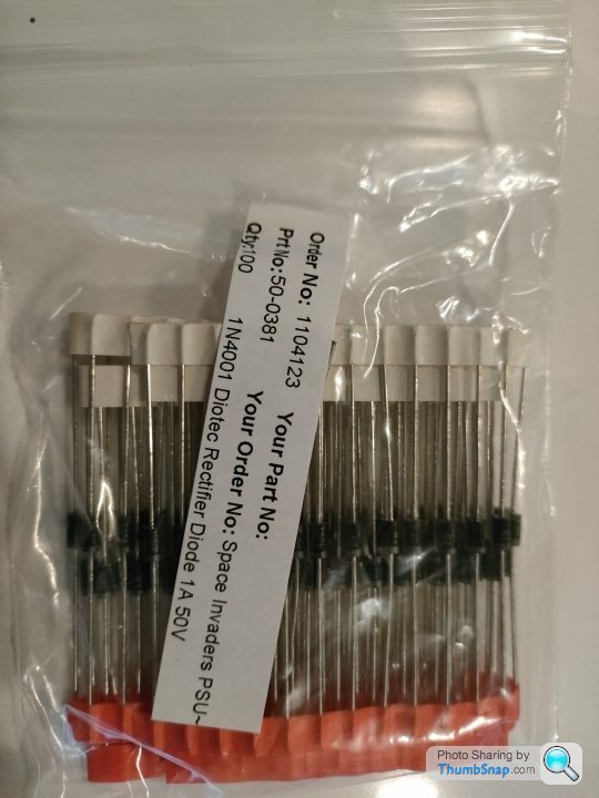
£3.95 for 25 from eBay which didn't seem too bad - link here but will probably expire in the future so just search for similar
Sorry, but just reading this thread, and I don't think that's the right diode for this application.A 'Zener' diode' is a specific device for dropping a certain voltage in a circuit (in this case 12V)
For relay circuits like this board, general purpose diode like IN4001 would be the correct component.
(I think it may work but not sure but better to have correct references for future)
RayTVR said:
For relay circuits like this board, general purpose diode like IN4001 would be the correct component.
(I think it may work but not sure but better to have correct references for future)
Yes - good point - hadn't clocked the Zener part in the product title in my rush to order a replacement - I'll see what other diodes I have around and see if any of them will be a better replacement.(I think it may work but not sure but better to have correct references for future)
As you say the Zener will still work as it will conduct in the required direction, it's just might not do the blocking in the other direction if it gets > 12V+ in the other / wrong direction (if my understanding of Zener diodes is correct!)
Penelope Stopit said:
Have no idea, although sometimes having to dabble with electronic circuits I have no idea how this circuit is built
It's all very interesting though
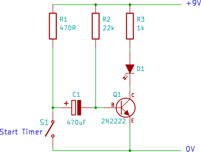
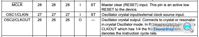
I think it might provide the clock for the PICs as they need a timing circuit on pin 27 if I am reading the datasheet correctly and the space for the IC is the same size as a 555 timer - also being a transistor with various capacitors and resistors connected to it it would lend itself to be a timer of some sortIt's all very interesting though
Something like this...
Juddder said:
I think it might provide the clock for the PICs as they need a timing circuit on pin 27 if I am reading the datasheet correctly and the space for the IC is the same size as a 555 timer - also being a transistor with various capacitors and resistors connected to it it would lend itself to be a timer of some sort
Something like this...
All could possibly be revealed if a few posters to this forum opened up their very same ECUsSomething like this...
Juddder said:
So while tracing out the pins to the IC4 which is the PIC that connects to the lower relay PCB I noticed this in the right hand corner of the board that looks very much like a blown resistor or diode
I've circled it in Orange below
Hopefully the PCB designer was a good electronics citizen and put the value of what it is (I think it says R7 next to it from the shot so should be a resistor) underneath the component on the PCB so I will desolder it tomorrow and see what it says
@Penelope Do you know what the IC circled in blue was meant to be? Looks like they've bodged a transistor in there with some jumper wires instead (*note to post above about good board design - looks like they ran out of components so just did the same as the TTL chip would do with a transistor and some wires - not beautiful!)
Note to anyone doing investigations like this - take lots of high res photos as you can study them and try and visually see where the problems are. When I initially opened the Door Control ECU it had that melted chip smell in there so I knew that it was highly likely something somewhere was blown on the board...
The component circled in orange looks more like a zener diode than a resistor and the bodged transistor circled in blue could have been fitted with an opto- coupler for isolation/screening purposes in a previous life. All these blown components are only to be expected if the modules have been subjected to a large over voltage or reverse polarity shoved up their jacksy, interesting thread all the same I've circled it in Orange below
Hopefully the PCB designer was a good electronics citizen and put the value of what it is (I think it says R7 next to it from the shot so should be a resistor) underneath the component on the PCB so I will desolder it tomorrow and see what it says
@Penelope Do you know what the IC circled in blue was meant to be? Looks like they've bodged a transistor in there with some jumper wires instead (*note to post above about good board design - looks like they ran out of components so just did the same as the TTL chip would do with a transistor and some wires - not beautiful!)
Note to anyone doing investigations like this - take lots of high res photos as you can study them and try and visually see where the problems are. When I initially opened the Door Control ECU it had that melted chip smell in there so I knew that it was highly likely something somewhere was blown on the board...
So tomorrow I'm going to try and get to the Steering Wheel ECU as well as the behaviour of the water pump staying on all of the time, and the steering wheel buttons not working is very reminiscent of this being blown / disconnected as well as referenced in this thread
In my car Fuse 7 provides power to the steering ECU & the effect of the fuse blowing is that the wipers and washer pump stick on, the main beam sticks on, steering wheel button's don't work among other weirdness. Therefore lack of power to the steering ECU seems to result in some strange behaviour from it.
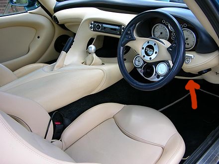
The location is described as being velcro'd to the inside of the lower steering wheel cover panel, which I'm guessing is the panel highlighted in the picture below with the arrow?
If so the helpful post above says there is a wing nut on the back so I'm guessing getting in there with a torch and looking to the back where one's knees usually are is probably around where it will be?
Anyone doing this before tips appreciated
In my car Fuse 7 provides power to the steering ECU & the effect of the fuse blowing is that the wipers and washer pump stick on, the main beam sticks on, steering wheel button's don't work among other weirdness. Therefore lack of power to the steering ECU seems to result in some strange behaviour from it.
The location is described as being velcro'd to the inside of the lower steering wheel cover panel, which I'm guessing is the panel highlighted in the picture below with the arrow?
If so the helpful post above says there is a wing nut on the back so I'm guessing getting in there with a torch and looking to the back where one's knees usually are is probably around where it will be?
Anyone doing this before tips appreciated
Gladers01 said:
The component circled in orange looks more like a zener diode than a resistor and the bodged transistor circled in blue could have been fitted with an opto- coupler for isolation/screening purposes in a previous life. All these blown components are only to be expected if the modules have been subjected to a large over voltage or reverse polarity shoved up their jacksy, interesting thread all the same
Yes I thought the same is it definitely doesn't look like a resistor but from a few more high resolution shots it is definitely labelled 'R27' and the 47n100 capacitor next to it is C13R27 could refer to the 898-3-R100K 100K resistor network and array white chip next to it but it doesn't seem quite right as the label is much more over towards the scorched component
I also measured the resistance of all the resistors around this part of the circuit and both R27 and R29 (left and bottom left of photo) both measured resistance across them of 8.16k (I will double check this) - but hopefully when I desolder it it will be easier to see (the other boxes have the direction of the diode on the PCB so hopefully that will help) [note: from studying the high resolution image below it looks like their is no diode polarity markings under the chip]
Maybe they switched the resistor for a diode to go with the swap of the transistor for the 6 pin chip where the bodged wiring is...
If anyone has a copy of the PCB layouts or the schematics that would be amazing, or even a few shots of another Door ECU PCB if anyone ever took any just to do some comparisons
Update:
So I took the best high resolution images my camera phone can do of the component and it's pretty much definitely a
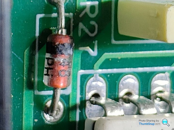
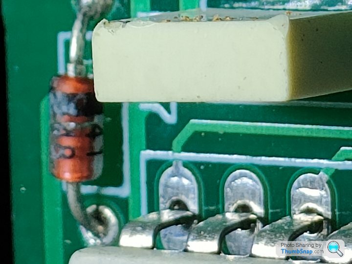
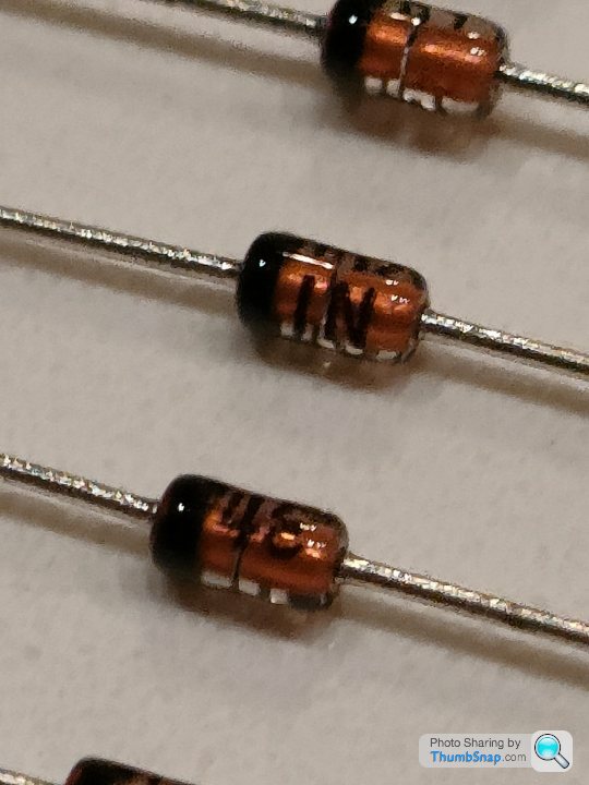
and here's a reference image from the ones I have clearly showing the 1N and the 41 and you can see the 41 and the slightly burnt 48 in the photos above
 |https://thumbsnap.com/hZWFgJWr[/url]
Edited by Juddder on Tuesday 14th December 17:31
Have you managed to work out what could possibly have caused the above ECUs to fail?
Hadn't given the cause much thought until recently
The fusebox dropping down couldn't create a short circuit apart from a main battery positive fusebox terminal (@ L) shorting to a good earth point which would result in a main battery fuse blowing if one is wired upstream into the main battery supply, without fusebox battery supply protection the supply cable would burn out from front to back
I would be looking for a rubbing rear loom and expecting to find an area where several cables had rubbed through and been shorting together or a screw digging into the rear loom shorting several cables together
Am thinking that the fusebox falling away from its mounting could have been enough to tug the loom and cause a damaged wiring harness to short out
Something, well much more than something suggests to me that there are underlying problems yet to be discovered
Hope this is possibly of some help and saves you from the nightmare of more ECU repairs in the near future if the above is proven to be the case
Penelope Stopit said:
Going by the number of ECU faults posted to PH, the ECUs are no worse than any other manufacturers ECU's
The lights ECU consists of 5 relays plus a few diodes and does look up to the job, standard headlight bulbs draw 5 Amps and the relays will be rated well above that
The lack of fused circuits leaves much to be desired
Running cables from the dashboard switches to a box of relays in the boot and then more wires from that box back up front to the headlights is unbelievable yet it happened
A fusebox and relay plate up front and down the back would make much sense
Thank you, that pretty much nails exactly how I see it, and I know next to nothing about auto electrics.The lights ECU consists of 5 relays plus a few diodes and does look up to the job, standard headlight bulbs draw 5 Amps and the relays will be rated well above that
The lack of fused circuits leaves much to be desired
Running cables from the dashboard switches to a box of relays in the boot and then more wires from that box back up front to the headlights is unbelievable yet it happened
A fusebox and relay plate up front and down the back would make much sense
I just can't get my head around the cables running all the way back and forth
Penelope Stopit said:
Have you managed to work out what could possibly have caused the above ECUs to fail?
Hadn't given the cause much thought until recently
Something, well much more than something suggests to me that there are underlying problems yet to be discovered
No not yet to be honest - had in my head thought that the fusebox falling backwards into the wheel arch might have caused it to find something metal to short a +12V on, and I think I replaced fuse 13 as maybe that blew too (it's been and continues to be a long journey so it's hard to completely remember!)Hadn't given the cause much thought until recently
Something, well much more than something suggests to me that there are underlying problems yet to be discovered
On your inklings of there are further problems to come, wait for the next post...


Gassing Station | Cerbera | Top of Page | What's New | My Stuff