Half the car is dead :-(
Discussion


Juddder said:
So tomorrow I'm going to try and get to the Steering Wheel ECU as well as the behaviour of the water pump staying on all of the time, and the steering wheel buttons not working is very reminiscent of this being blown / disconnected as well as referenced in this thread
In my car Fuse 7 provides power to the steering ECU & the effect of the fuse blowing is that the wipers and washer pump stick on, the main beam sticks on, steering wheel button's don't work among other weirdness. Therefore lack of power to the steering ECU seems to result in some strange behaviour from it.
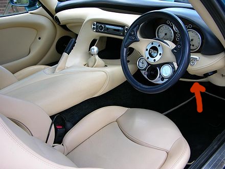
The location is described as being velcro'd to the inside of the lower steering wheel cover panel, which I'm guessing is the panel highlighted in the picture below with the arrow?
If so the helpful post above says there is a wing nut on the back so I'm guessing getting in there with a torch and looking to the back where one's knees usually are is probably around where it will be?
Anyone doing this before tips appreciated
There's quite a few posts I made with photos when repairing my split cable.In my car Fuse 7 provides power to the steering ECU & the effect of the fuse blowing is that the wipers and washer pump stick on, the main beam sticks on, steering wheel button's don't work among other weirdness. Therefore lack of power to the steering ECU seems to result in some strange behaviour from it.
The location is described as being velcro'd to the inside of the lower steering wheel cover panel, which I'm guessing is the panel highlighted in the picture below with the arrow?
If so the helpful post above says there is a wing nut on the back so I'm guessing getting in there with a torch and looking to the back where one's knees usually are is probably around where it will be?
Anyone doing this before tips appreciated
The panel is held by:
Drivers side inner wing is a wing nut at the back to release the righthand side. There's velco at the front and a bolt holding the left side to the tunnel that needs a 10mm socket.
There's only two? plugs connecting the steering wheel column, blue and black so if you remove the nut and bolt from the steering column adjust, making careful note of the order all the parts are in, the column comes straight out making it very easy to work on.
Mark up the ribbon cables to where they attach so you know which way around they go. Its easy to misalign or reverse them.
https://www.pistonheads.com/gassing/topic.asp?h=0&...

from
http://tvr-cerbera.co.uk/WorkshopWiringDiagrams/St...
Also, if you get into the steering wheel, the buttons are connected via 2 pin plugs. Mark which ones they are
https://www.pistonheads.com/gassing/topic.asp?h=0&...
https://www.pistonheads.com/gassing/topic.asp?h=0&...
Edited by Byker28i on Thursday 16th December 09:45
Byker28i said:
Shout if you need any photos and I'll take some for you
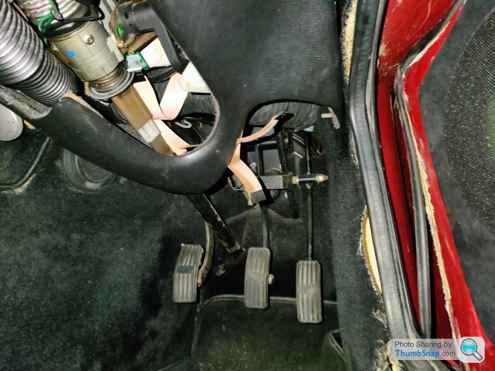
That's great, many thanks and yes it was your post I referenced above so that's been super helpfulYesterday I managed to get in the drivers footwell of my car and found the wing nut you mention and took a photo of it just so any future selves can reference it - you can see it on the right middle in this photo to the diagonal top right of the top of the accelerator pedal
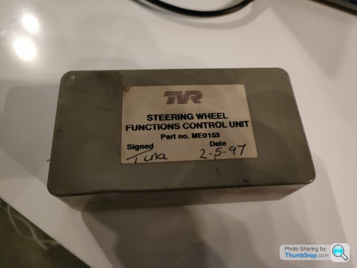
Attached to the back is the Steering Wheel ECU which is even more of a fudge job that the boxes in the boot - mine is hand-cut to fit the plugs and only had three screws in it - you can see the 9x9 connector with keyed pin as per the other boxes for the high current inputs and outputs, the 10 pin head connector for the steering wheel ribbon that the steering wheel buttons connect to and the 5 pin head connector for the indicator stalk and hazard button
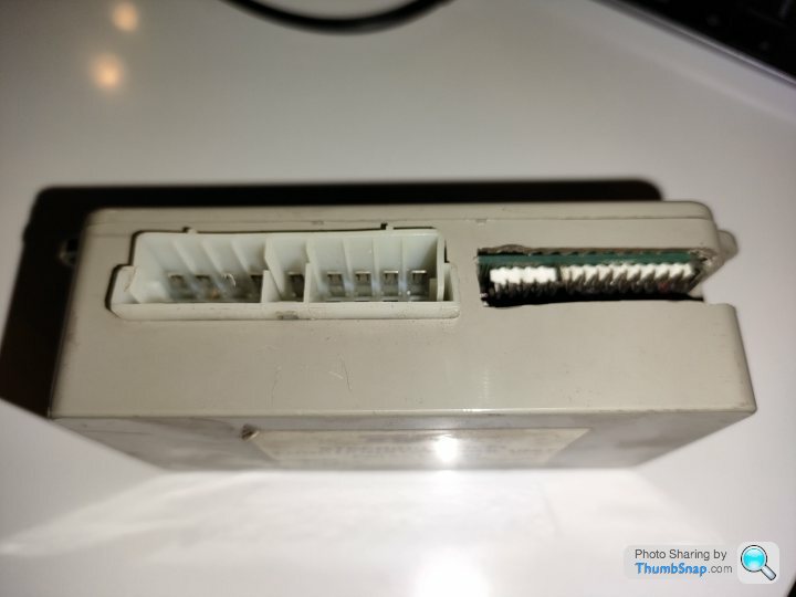
On closer inspection I think I've figured out why mine isn't working...
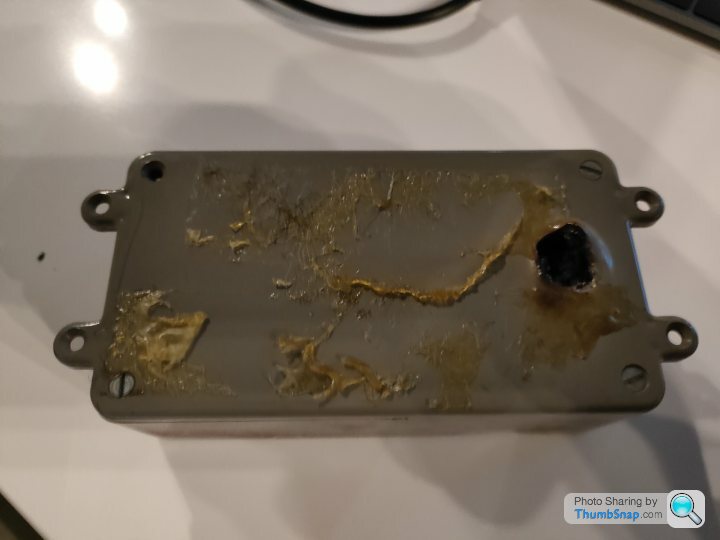
For something to melt like that means it a. wasn't fused and b. didn't like getting 12V shorted through it so time to open it up and have a look...
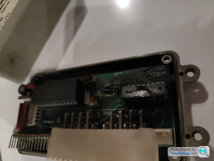
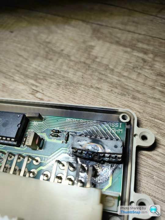
As you can see there is a TTL chip over by the high current 9x9 connector that has literally melted with the voltage and burnt through the PCB on the way - I've seen them crack before but never quite melt like this!
The good news is we can see the wiring traces, and the PIC (*same as Microchip PIC16C57C used on the Door ECU) so we can read that to download the ROM code and potentially either jumper the wires or do similar where the PCB has melted
I think I should also be able to emulate / do similar behaviour to this box with an Arduino, a +12V to +5V transformer and some relays so I'm going to have a think and see what will work best - might be better just to start with a new circuit and some more modern electronics...
and this is the part of the main harness wiring diagram I'm going to need which shows the Steering Column connector as per Biker's diagram above and the Steering Column ECU which is the part I will need

and here's the connections for the signal and high current drive part of the ECU
A1 - N/C
A2 - Headlamp Signal (V)
A3 - N/C
A4 - N/C
A5 -
A6 - Wiper 2 Signal (R/S)
A7 - Main Beam Signal (U/W)
A8 - Dip Beam Signal (U/S)
A9 - Turn Left Signal (?)
B1 - Ignition (O)
B2 - Horn Drive (F/S?)
B3 - Hazard Drive (W/R?)
B4 - Battery (R)
B5 - Earth (B)
B6 - Wiper 1 Signal (V/O?)
B7 - N/C
B8 - Washer Signal (U/V)
B9 - Turn Right Signal (G/W?)
Notes:
A2 is connected to Dash Switch A5 Headlamp Signal, and thus J30 (to rear harness) pin 19
Most of the other signals also feed into J30 for travel to the ECUs in the rear
Edited by Juddder on Thursday 16th December 16:48
Byker28i said:
There's a few of the indicator and hazard units for sale on ebay, all from Douglas Valley Breakers, for around £55-60. Worth asking if he has a steering wheel functions unit for the same sort of price which would save you some work?
Yes many thanks and good idea 
I already bought from them the last Ignition ECU they had and an extra Hazard / Lights ECU a couple of weeks ago when I started on this journey so I think I have everything from them they have that will help unluckily. Another suggestion was to try TVR Glen so I will ping him / them a message today and see what they might have
FarmyardPants said:
What percentage of the car is still dead? Any updates?
Well I've been away from the car for nearly a month with Christmas etc. but I have been working on building my own Door Control ECU to replace the ones that TVR made out of an Arduino Mega and a daughter relay shield Any updates?I've pretty much finished the programming and now need to get to the hardware and do some actual testing so I will report back when I have - it might be in a couple of weekends with a bit of luck :-) [edit: probably longer as I have no idea how well this will work or not
 ]
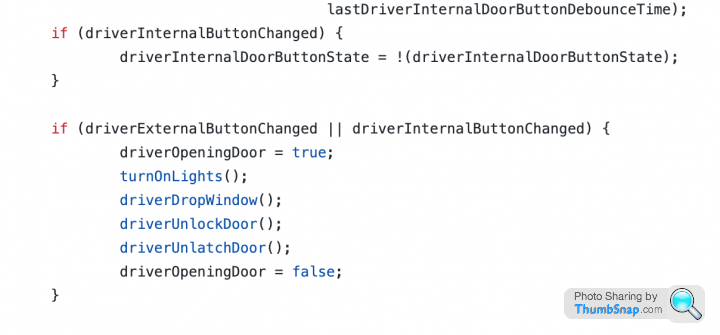
]Here's a sneak peak...
and we can copy and potentially improve the door opening process of the original Door ECU box and maybe even add some nice things like flashing the headlights or similar
Edited by Juddder on Wednesday 5th January 14:27
Sounds like a fun project. Will it integrate with the existing immobiliser or are you going to incorporate the concept of locking and immobilising into the code? You could use a remote control latching relay to arm/lock the car. I have automated my doors and boot with remote control but the problem is the radio frequency is congested and I sometimes go into the garage to find the doors open because someone opened their garage or something  so I have an inline switch to turn it off. I patched into the exterior buttons so the remote only works when the car is unlocked. But it's quite cool to walk up to the car with the remote in your pocket and have the door pop open before you get there
so I have an inline switch to turn it off. I patched into the exterior buttons so the remote only works when the car is unlocked. But it's quite cool to walk up to the car with the remote in your pocket and have the door pop open before you get there Edited by FarmyardPants on Wednesday 5th January 17:13
FarmyardPants said:
Sounds like a fun project. Will it integrate with the existing immobiliser or are you going to incorporate the concept of locking and immobilising into the code? ... But it's quite cool to walk up to the car with the remote in your pocket and have the door pop open before you get there
That does sound cool and yes thinking about it I could potentially add an IR module to the Arduino to add as a 3rd door button press for each doorMy plan with the immobiliser is to find an alarm switched +12V feed and use that to power the Arduino so that it's not powered on all of the time and draining battery power from the main +12V feed
The boot time of an Arduino without a boot loader is < 0.5s [reference here] so it should in theory be fast enough to respond with no lag once the alarm is disabled, and you then press the door button - I would imagine even with a boot loader at ~2s it's probably not too bad
All things to try out when I have some hardware connected and bits of the car to try out - I will report back...
Juddder said:
Well I've been away from the car for nearly a month with Christmas etc. but I have been working on building my own Door Control ECU to replace the ones that TVR made out of an Arduino Mega and a daughter relay shield
I've pretty much finished the programming and now need to get to the hardware and do some actual testing so I will report back when I have - it might be in a couple of weekends with a bit of luck :-) [edit: probably longer as I have no idea how well this will work or not]
Here's a sneak peak...
and we can copy and potentially improve the door opening process of the original Door ECU box and maybe even add some nice things like flashing the headlights or similar
I'm in, this is a super duper ideaI've pretty much finished the programming and now need to get to the hardware and do some actual testing so I will report back when I have - it might be in a couple of weekends with a bit of luck :-) [edit: probably longer as I have no idea how well this will work or not
]Here's a sneak peak...
and we can copy and potentially improve the door opening process of the original Door ECU box and maybe even add some nice things like flashing the headlights or similar
Looking forward to more posts about your progress
Will you use a regulated supply to the Arduino?
Deserves its own topic
Juddder said:
Penelope Stopit said:
Have you managed to work out what could possibly have caused the above ECUs to fail?
Hadn't given the cause much thought until recently
Something, well much more than something suggests to me that there are underlying problems yet to be discovered
No not yet to be honest - had in my head thought that the fusebox falling backwards into the wheel arch might have caused it to find something metal to short a +12V on, and I think I replaced fuse 13 as maybe that blew too (it's been and continues to be a long journey so it's hard to completely remember!)Hadn't given the cause much thought until recently
Something, well much more than something suggests to me that there are underlying problems yet to be discovered
On your inklings of there are further problems to come, wait for the next post...

DuncanM said:
This is hero stuff!
Heater ECU next would be great
I've been working on some arduino code for the heater ECU. Shared from my Google Drive here.Heater ECU next would be great
https://drive.google.com/file/d/11IcblepCbE1gJqaWl...
My heater box works currently but I have checked this with a very shoddily assembled set of hardware (Arduino Mega with relay & MOSFET boards attached and a step down converter PSU or 2) and it worked on my car. Being an early car mine has the added complication of a solenoid controlled flap in the output from the heater box. First time I've done any sort of coding so it took a while and there may well be a neater way of doing it for people who do this more often. Given my heater box works (thanks Jody!) and I've got bigger problems (leaking water pump) to fix I've given up on this for now.
Edited by CerbWill on Friday 7th January 18:02
Penelope Stopit said:
DuncanM said:
This is hero stuff!
Heater ECU next would be great
Yes, today the locking tomorrow the worldHeater ECU next would be great
I may have to dig mine out. Last used for a light wand for writing words on long exposure photos...
Byker28i said:
Hum, you joke, but as arduinos have stacking interfaces.... Is there a possibility of replacing multiple boxes with just one?
I may have to dig mine out. Last used for a light wand for writing words on long exposure photos...
OK - as everyone seems quite excited and doesn't think I'm completely mad it's time for a bit of show and tell... I may have to dig mine out. Last used for a light wand for writing words on long exposure photos...
So for testing I'm going to use either a Arduino Mega or Uno with a Seed Studio Relay Shield as per this
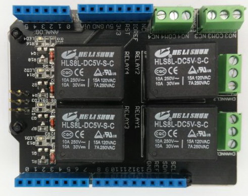
There's only 4 relays on this, but I can test the mechanism for the drivers door if I rig up driver door latch, driver door lock, window up and window down
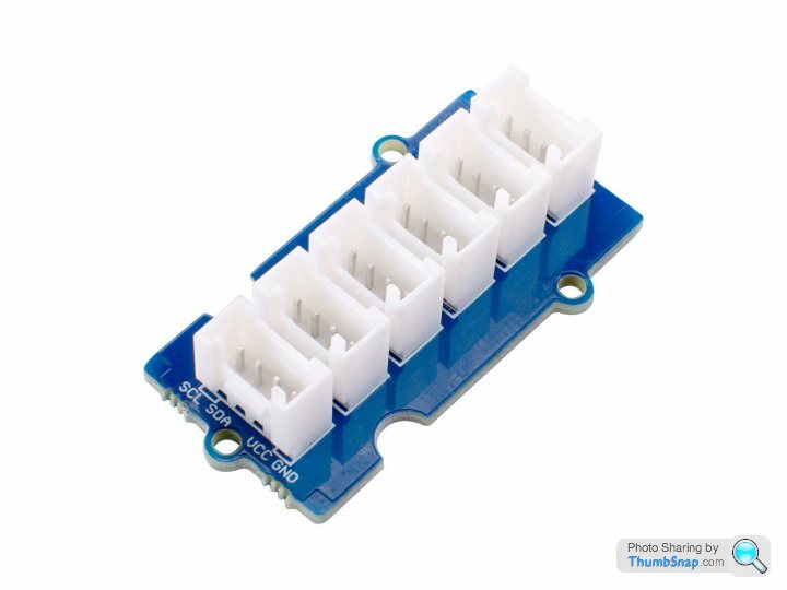
Once I have this working it's either plugging in another one of these for the passenger door, using the same program but just with the inputs for the passenger connectors connected, or moving over to my master plan which is one of these...
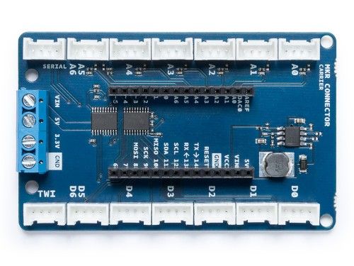
With the Seeed Studio Grove shield I can connect 14 of these each with a relay which basically covers all of the
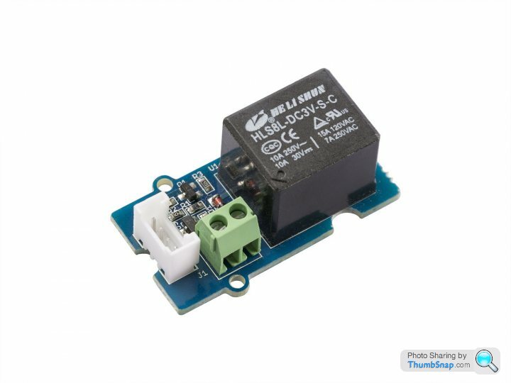
We can also use the Grove kit with hubs for extra ports (*we'll need input ports as well for the buttons etc.) and potentially even add super crazy stuff like fingerprint detection or accelerometers (*but that's not my intent at this point, just to get my car working again
)
Bear with me as I've been writing the code blind as I wait for the hardware to arrive but it compiles and runs and all of the test suite for each function seems to do what I want.
Hardware should be united with me when I'm back in the UK next week, including buck-boost adapters for the +12V supply to drop it to +5V for the Arduinos so I can try some actual switching of 12V electrics and see how we get on and then I'll post up the GitHub link for others to play along too
Edited by Juddder on Friday 7th January 16:31
Byker28i said:
Penelope Stopit said:
DuncanM said:
This is hero stuff!
Heater ECU next would be great
Yes, today the locking tomorrow the worldHeater ECU next would be great
I may have to dig mine out. Last used for a light wand for writing words on long exposure photos...
"tomorrow the world" is a phrase often used for moving forward to greater achievements
Was originally going to post tomorrow the whole car but that didn't come across as good enough for such a great idea
Juddder said:
OK - as everyone seems quite excited and doesn't think I'm completely mad it's time for a bit of show and tell...
So for testing I'm going to use either a Arduino Mega or Uno with a Seed Studio Relay Shield as per this
There's only 4 relays on this, but I can test the mechanism for the drivers door if I rig up driver door latch, driver door lock, window up and window down
Once I have this working it's either plugging in another one of these for the passenger door, using the same program but just with the inputs for the passenger connectors connected, or moving over to my master plan which is one of these...
With the Seeed Studio Grove shield I can connect 14 of these each with a relay which basically covers all of theinputs outputs I could think of and means we can probably get rid of a lot more than just the door control ECU with one single Arduino + Grove shield setup
We can also use the Grove kit with hubs for extra ports (*we'll need input ports as well for the buttons etc.) and potentially even add super crazy stuff like fingerprint detection or accelerometers (*but that's not my intent at this point, just to get my car working again )
Bear with me as I've been writing the code blind as I wait for the hardware to arrive but it compiles and runs and all of the test suite for each function seems to do what I want.
Hardware should be united with me when I'm back in the UK next week, including buck-boost adapters for the +12V supply to drop it to +5V for the Arduinos so I can try some actual switching of 12V electrics and see how we get on and then I'll post up the GitHub link for others to play along too
Nothing mad about any of thisSo for testing I'm going to use either a Arduino Mega or Uno with a Seed Studio Relay Shield as per this
There's only 4 relays on this, but I can test the mechanism for the drivers door if I rig up driver door latch, driver door lock, window up and window down
Once I have this working it's either plugging in another one of these for the passenger door, using the same program but just with the inputs for the passenger connectors connected, or moving over to my master plan which is one of these...
With the Seeed Studio Grove shield I can connect 14 of these each with a relay which basically covers all of the
We can also use the Grove kit with hubs for extra ports (*we'll need input ports as well for the buttons etc.) and potentially even add super crazy stuff like fingerprint detection or accelerometers (*but that's not my intent at this point, just to get my car working again
)Bear with me as I've been writing the code blind as I wait for the hardware to arrive but it compiles and runs and all of the test suite for each function seems to do what I want.
Hardware should be united with me when I'm back in the UK next week, including buck-boost adapters for the +12V supply to drop it to +5V for the Arduinos so I can try some actual switching of 12V electrics and see how we get on and then I'll post up the GitHub link for others to play along too
Technology has moved on much since the cars were built
Are we all to sit back and watch or are you open to input?
Penelope Stopit said:
Are we all to sit back and watch or are you open to input?
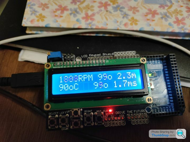
Yes please - I'm just working away on my own so all input very welcomeI'll also share the Arduino ECU diagnostics I built when I was working with Ade (RSAJP) and Greg (OSAJP) on an Arduino version - shows what these little Arduinos can do with a shield or two
Gassing Station | Cerbera | Top of Page | What's New | My Stuff