Light control box modification - pic
Discussion


Hi all,
I finished the modification to my lights switching box. This mod is useful if you've fitted HID (Xenon) lamps to the dip beams on a later style Cerb, as it makes the dip beam stay on when you switch to main beam.
As the HIDs have a ballast circuit and take a few seconds to come to full brightness, its not appropriate to have the control box switching BETWEEN dip and main - you need to keep the dips on.
Modification:
1. Unplug box, remove 4 screws on connector end of box, remove PCB;
2. Solder two diodes between the main beam output connections and the dip beam connection. Diodes should be cathode (stripe) towards the dip beam connection; Scrape a little of the varnish off the PCB pad where the diodes meet to enable it to be soldered.
3. Replace PBC in box, replace cover and screws, reconnect to car.
The diodes I used are 1N5004 types, which are 10A current. Although the HIDs don't draw this all the time, there is a relatively high inrush current when they strike.
Picture of completed mod:

Of course, you undertake this modification at your own risk, I cannot be held responsible if your car explodes.
- Andy.
I finished the modification to my lights switching box. This mod is useful if you've fitted HID (Xenon) lamps to the dip beams on a later style Cerb, as it makes the dip beam stay on when you switch to main beam.
As the HIDs have a ballast circuit and take a few seconds to come to full brightness, its not appropriate to have the control box switching BETWEEN dip and main - you need to keep the dips on.
Modification:
1. Unplug box, remove 4 screws on connector end of box, remove PCB;
2. Solder two diodes between the main beam output connections and the dip beam connection. Diodes should be cathode (stripe) towards the dip beam connection; Scrape a little of the varnish off the PCB pad where the diodes meet to enable it to be soldered.
3. Replace PBC in box, replace cover and screws, reconnect to car.
The diodes I used are 1N5004 types, which are 10A current. Although the HIDs don't draw this all the time, there is a relatively high inrush current when they strike.
Picture of completed mod:
Of course, you undertake this modification at your own risk, I cannot be held responsible if your car explodes.
- Andy.
Edited by alinton on Monday 1st January 18:44
Edited by alinton on Monday 1st January 18:46
http://uk.farnell.com/jsp/endecaSearc
I use these for all sorts of applications on cerbs .. including a recent lighting mod on a cerb with HID conversion.
I use these for all sorts of applications on cerbs .. including a recent lighting mod on a cerb with HID conversion.
Oh sorry. I meant try those suppliers for *any* automotive diode (I give that description to any cheap standard diode). I'm sure an IN5401G would be OK too. 24p from Maplin with high current capability. Stick the word "diode" into the Maplin search engine and ignore anything with "zener" in front.

That's great...I will be doing that mod as part of my general scheme to improve lighting. Main & dip on at the same time will be a great improvement. Currently I have halogen in both main & Dip but am thinking of going HID. My old griff had HID main, halogen dip, but I can see the sense of putting the HID on the dip instead.
Am I correct in recalling that the control box deliveres a reduced voltage to the dip beam lights when on side light setting, so the bulbs burn at a lower level. How does the HID unit cope with this? Or is it better to disable this function (How?) an rely on the side light bulbs.
Jon H
Am I correct in recalling that the control box deliveres a reduced voltage to the dip beam lights when on side light setting, so the bulbs burn at a lower level. How does the HID unit cope with this? Or is it better to disable this function (How?) an rely on the side light bulbs.
Jon H
It is necessary to disable this when using HIDs; You need to cut and insulate a wire coming from the dim/dip box - the small box on the right in the boot.
I _think_ its the black/red wire but can't be sure and I'm not home to check. If you've a voltmeter then its the one with about 7 volts on it when sidelights are on.
Perhaps someone else can confirm the wire colour.
Andy.
I _think_ its the black/red wire but can't be sure and I'm not home to check. If you've a voltmeter then its the one with about 7 volts on it when sidelights are on.
Perhaps someone else can confirm the wire colour.
Andy.
Here is some info from a prior thread I posted on.
There are two control boxes in the boot. Dim/Dip Switching Unit and the Dim/Dip Unit.
Its the Dim/Dip Unit that feeds the voltage into the switching unit.
The Dim/Dip unit has 6 wires going into it.
Red, Red/White, Red/Black, Black, Green and Blue/Yellow.
The Red/Black is the signal wire to the switching unit.
Disconnect the red/black wire and tape it to the unit so its insulated and out of the way.
I suspect the entire unit can be removed but I preferred to disconnect a single wire so I didn't have earths and ignition feeds floating about not connected.
I also think a better way of turning off the dim dip would be to disconnect the ignition or sidelight feeds into the unit (green and red/white respectively) so that the unit never puts a voltage onto the red/black wire. But I haven't gotten around to trying it yet.
alinton said:
Hi all,
I finished the modification to my lights switching box. This mod is useful if you've fitted HID (Xenon) lamps to the dip beams on a later style Cerb, as it makes the dip beam stay on when you switch to main beam.
As the HIDs have a ballast circuit and take a few seconds to come to full brightness, its not appropriate to have the control box switching BETWEEN dip and main - you need to keep the dips on.
Modification:
1. Unplug box, remove 4 screws on connector end of box, remove PCB;
2. Solder two diodes between the main beam output connections and the dip beam connection. Diodes should be cathode (stripe) towards the dip beam connection; Scrape a little of the varnish off the PCB pad where the diodes meet to enable it to be soldered.
3. Replace PBC in box, replace cover and screws, reconnect to car.
The diodes I used are 1N5004 types, which are 10A current. Although the HIDs don't draw this all the time, there is a relatively high inrush current when they strike.
Picture of completed mod:
Of course, you undertake this modification at your own risk, I cannot be held responsible if your car explodes.
- Andy
I want to do this mod, but the picture has gone now.I finished the modification to my lights switching box. This mod is useful if you've fitted HID (Xenon) lamps to the dip beams on a later style Cerb, as it makes the dip beam stay on when you switch to main beam.
As the HIDs have a ballast circuit and take a few seconds to come to full brightness, its not appropriate to have the control box switching BETWEEN dip and main - you need to keep the dips on.
Modification:
1. Unplug box, remove 4 screws on connector end of box, remove PCB;
2. Solder two diodes between the main beam output connections and the dip beam connection. Diodes should be cathode (stripe) towards the dip beam connection; Scrape a little of the varnish off the PCB pad where the diodes meet to enable it to be soldered.
3. Replace PBC in box, replace cover and screws, reconnect to car.
The diodes I used are 1N5004 types, which are 10A current. Although the HIDs don't draw this all the time, there is a relatively high inrush current when they strike.
Picture of completed mod:
Of course, you undertake this modification at your own risk, I cannot be held responsible if your car explodes.
- Andy
However I could have sworn I had seen a different mod to achieve the same thing that only involved cutting a track.
But this is all I can find.
I could be very well be wrong but the above mod seems to be using the power from the main beam to also power the dip beams.
I'd rather find a way of keeping the dips running from their own power. If there is a mod involving cutting a track, I guess that would just be stopping the dips circuit shutting off....
There is a different mod, which might be causing confusion:
For the pod-style lights, from the factory the dipped lamps are given 7v when just the sidelights are on (as well as 12v to the actual sidelights of course) which makes the dipped filament bulbs glow dimly. If you fit HIDs to the dipped, this 7v makes them flicker. There is a mod to snip one of the wires to the dim/dip box which stops any voltage being sent to the dipped lights when on sidelights.
I'm not sure if you are confusing this with alinton's mod, Lucky one?
FarmyardPants said:
There is a different mod, which might be causing confusion:
For the pod-style lights, from the factory the dipped lamps are given 7v when just the sidelights are on (as well as 12v to the actual sidelights of course) which makes the dipped filament bulbs glow dimly. If you fit HIDs to the dipped, this 7v makes them flicker. There is a mod to snip one of the wires to the dim/dip box which stops any voltage being sent to the dipped lights when on sidelights.
I'm not sure if you are confusing this with alinton's mod, Lucky one?
Yes that different mod is discussed towards the end of that old thread. For the pod-style lights, from the factory the dipped lamps are given 7v when just the sidelights are on (as well as 12v to the actual sidelights of course) which makes the dipped filament bulbs glow dimly. If you fit HIDs to the dipped, this 7v makes them flicker. There is a mod to snip one of the wires to the dim/dip box which stops any voltage being sent to the dipped lights when on sidelights.
I'm not sure if you are confusing this with alinton's mod, Lucky one?
I'm putting LEDs in & they seem happy with the 7v feed. Coming on a lot dimmer (with no flicker) just as the old halogen bulbs did. So I'm very keen to keep that feature as I fitted the little side light bulbs in the main beam units meaning with the side lights on I have all 4 lights on at the same (lowish) brightness.
I just want my new dip beam LED bulbs to stay on with the separate main beam bulbs.
I should have done this mod years ago when I first fitted the twin pod lights, I just never got round to it, there was always something more pressing to fix on the car!
Ok so I've been doing some testing my self, I'm reasonably sure these bits are for:
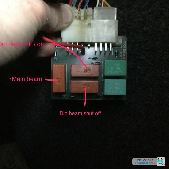
The RTD14012 (the orange things) are just two way relays. One just turns the lights on, the other is the one that cuts the power to the dips when you put on the main beams.
I can't find any info on the VTA00112 (the green things) but they seem to be just a different type of relay. I was only bothered because the dip beam output runs to one of them, but it seems to be the fog light relay, seems logical as you need the dips on to have the fog light on. To back up my thinking I realised that should mean the fog light turned off when you put the main beam on - it did!
So it seems all I need to do is connect these two points permanently together (they are the normally closed terminals)

I tried gingerly shorting them with the main beam on, nothing blew up & I heard the fans of the LEDs kick in so it's looking good. Just need to pluck up courage to make a permanent connection now.
The RTD14012 (the orange things) are just two way relays. One just turns the lights on, the other is the one that cuts the power to the dips when you put on the main beams.
I can't find any info on the VTA00112 (the green things) but they seem to be just a different type of relay. I was only bothered because the dip beam output runs to one of them, but it seems to be the fog light relay, seems logical as you need the dips on to have the fog light on. To back up my thinking I realised that should mean the fog light turned off when you put the main beam on - it did!
So it seems all I need to do is connect these two points permanently together (they are the normally closed terminals)
I tried gingerly shorting them with the main beam on, nothing blew up & I heard the fans of the LEDs kick in so it's looking good. Just need to pluck up courage to make a permanent connection now.
Yes, works fine. The dip beam now stays on with the main beam. I'm not running any other relays down stream, so doing it this way both the dips & main beam continue to use their own power supplies (the LED lights take less current).
My dim dip still works fine, the main beam will still flash with the dim dips on. The only other difference is the rear fog light stays on when the main beam comes on, but that's not really of any relevance.
Those blobs of solder is all it needs:

My dim dip still works fine, the main beam will still flash with the dim dips on. The only other difference is the rear fog light stays on when the main beam comes on, but that's not really of any relevance.
Those blobs of solder is all it needs:
I'm sorry to have to say, but the above is not great advice! Most definitely not the correct way to do it and in actual fact can be a fire risk.
On the back of the module there is a small blue/white, and small blue/red, get any diode you can lay your hand on (1n4007 is standard but pretty much any diode will work) and intercept the two.
Cathode (striped end) on blue/red, anode (clear end) on blue/white.
Its done like that for a reason, please don't change it, and don't do it any other way and it could trash whats left of your already trashed plug and board header (change these too, please!). The fact your fog lights are on as well is a cause for concern and proves my thought that current is being fed elsewhere through the board in an incorrect fashion!
As for the dim-dip issue on HIDs - on the dim-dip control unit, there is a thick red wire and a thick blue/red wire, join these together, take out the DIM Dip control unit and DIM DIP ecu completely and IGNORE all of the other wires, job done forever, safely. The 7v output is actually not 7v, but a Pulse width signal switching around 1000 times a second, you need an oscilloscope to see it, and will work perfectly well with LEDs.
If anyone is confused as to what to do or how to do either of the above SAFELY - RING ME (074OO 889449)
You actually have a very early model control unit, Luckyone (the name is actually ironic, as you're a luckone this hasn't caught fire). the later cars are very different, and there is a different method for doing that which involves putting the diode directly on the board, again, if unsure. ring me, please.
Jody
Edited by tofts on Wednesday 20th December 15:50
Seems like we were only chatting about Cerbera control boxes over on Facebook the other day Jody (wipers that time)!
For reference on this thread here's what I believe is the original diode mod with a picture and instructions:
https://www.pistonheads.com/gassing/topic.asp?t=72...
1. Unplug box, remove 4 screws on connector end of box, remove PCB;
2. Solder two diodes between the main beam output connections and the dip beam connection. Diodes should be cathode (stripe) towards the dip beam connection; Scrape a little of the varnish off the PCB pad where the diodes meet to enable it to be soldered.
3. Replace PBC in box, replace cover and screws, reconnect to car.
The diodes I used are 1N5004 types, which are 10A current. Although the HIDs don't draw this all the time, there is a relatively high inrush current when they strike.

Gassing Station | Cerbera | Top of Page | What's New | My Stuff