Engine rebuild
Discussion


Once again, thank you!
I made it over to Ricky’s this morning. Updates will follow soon enough, but sadly not immediately. The block and heads are with a specialist machine shop in Kent. They were awaiting the cylinder liners before they started. As of today, the scored block has been bored and eight of the liners machined into place. The old, worn valve guides have been pressed out and fitting the new ones shouldn’t take too long.
When they’re finished, Ricky will drive down to Kent to collect them in person so that he can inspect the work. Hopefully the build-up should then be pretty quick.
I’m also having one or two other things sorted whilst the car is off the road, but I’ll write about them as they happen........
I’m as impatient as anybody, but I want this done well and that means time and patience! Fingers crossed for some noticeable progress in the near future.
Although I was quite willing to thrash the engine on the road, I was always dubious about doing so on a dyno. It just seemed a sure-fire way of ensuring the catastrophic mechanical failure of an already worn engine. The thought did cross my mind of doing so to get “before” and “after” figures, but thought that that would REALLY be pushing my luck!
Ricky will use the car for a few days to bed the motor in and will be flashing the ECU with one of his custom maps. After an oil change it’ll be over to me. I’ll agree a regime with him, but I expect, as with any modern engine, it’ll be taking it steady, with no labouring for a couple of hundred miles, and then steadily upping the pace before another oil change at 1000 miles. But as ever, I’ll detail it here when I know more. Professional advice is always welcome!
And yes, it’ll be dyno’d when we’re satisfied that it’s well bedded-in.
Standby........ standby........
The delay has been frustrating and I’ll endeavour to explain the “whys” and “wherefores” when I next post about the rebuild itself........
Which I’m pleased to report should be soon! The block and heads are finally ready for collection. It was machining the former that was causing the delay. I believe that they should be back in Ricky’s hands within the next day or two.
Well…………
After a lengthy and unwelcome hiatus, it’s time to resume this thread!!
Hooray!!!
I shall remind you that I’m only a two finger typist. (Actually, lying abed in a hotel in Vienna, alarm set for 0450 BST, Sunday morning, iPad resting on my chest, strictly speaking I’m a two thumbs typist!) So forgive me if I keep the recaps to a minimum.
But you may recall that the time frame from initially asking for recommendations for a rebuild specialist, to buying a knackered Mk1 focus to get me by, to dropping the car off with Ricky, was short: three weeks?: a month? And I’ve been mindful throughout that Ricky, until recently a sole trader, has to maintain a steady income through bread-and-butter work: servicing: aftermarket exhausts: remaps......
Still.... I suspect that we both thought that I’d be back on the road with a rebuilt engine by early summer. Five months maybe?
The engine came out of my car in very short order and was stripped straight away. Ricky ordered all of the parts that he would need, many of them for bespoke manufacture stateside, whilst the block went away for specialist work at a third party contractor......
And somewhere along the line a b k was dropped.
I want to make it quite clear that it wasn’t Ricky’s fault in the slightest. He’s been between a rock and a hard place for a few months. My block needed extensive machine work, and one false move would require the purchase of a new £5500 casting. Second hand, the 5.2s are available. But not the 5s.
So the work needed to be done by extremely competent people and they are few and far between. For this sort of work, Ricky sends his blocks and heads to the best. I know of them by reputation and if I name them, then you may well have heard of them too. But I’m not going to name names! Which is a pity as their work is superb.
Because somewhere along the line, their organisational skills were found lacking.
It was up to them to order the liners, from LA Sleeve in........ well, Santa Fe as it happens! And whilst the bespoke pistons and valve-train were manufactured and delivered from the States in about a month, the liners apparently took ten weeks!
And the work that should have taken one highly-skilled machinist a week to complete took...... another two-and-a-half months!
The trouble is that there are so few machine shops in the UK whom you would trust this work to. Many will tell you that they could do the work, but what’s their track record? Ricky has to rely on their work being spot-on every time, so you go with the best. And if they’ve forgotten to order the liners for one small job? Or if they sideline the work of one small, sole trader in favour of a bigger, more lucrative job, what do you do? Do you alienate the machine shop who you trust to get the job right?
So, over five months after he sent it off, Ricky received my block (and heads) back from the machinists.
And they’ve done a beautiful job!
Albeit a rather slow one....... But what could he do? This is work that HAS to be outsourced. And it HAS to go to the best. And they’ll survive quite happily without his custom, so you suck it up.
I understand that.
Doesn’t make it any less frustrating though!
Right! My thumbs are aching! And I need to sleep before another day of driving airliners around. Tomorrow, after tapas and Estrella in Barcelona (and if I can then be arsed!) I’ll write about that actual block work, complete with the “why’s” and “where fore’s”.
And some photos!!
After that comes an absolutely fascinating insight into con rods!! (No, really! It’s actually, genuinely fascinating!!! I was quite blown away by it. Trust me, it’ll be worth the wait........)
After a lengthy and unwelcome hiatus, it’s time to resume this thread!!
Hooray!!!
I shall remind you that I’m only a two finger typist. (Actually, lying abed in a hotel in Vienna, alarm set for 0450 BST, Sunday morning, iPad resting on my chest, strictly speaking I’m a two thumbs typist!) So forgive me if I keep the recaps to a minimum.
But you may recall that the time frame from initially asking for recommendations for a rebuild specialist, to buying a knackered Mk1 focus to get me by, to dropping the car off with Ricky, was short: three weeks?: a month? And I’ve been mindful throughout that Ricky, until recently a sole trader, has to maintain a steady income through bread-and-butter work: servicing: aftermarket exhausts: remaps......
Still.... I suspect that we both thought that I’d be back on the road with a rebuilt engine by early summer. Five months maybe?
The engine came out of my car in very short order and was stripped straight away. Ricky ordered all of the parts that he would need, many of them for bespoke manufacture stateside, whilst the block went away for specialist work at a third party contractor......
And somewhere along the line a b
k was dropped.I want to make it quite clear that it wasn’t Ricky’s fault in the slightest. He’s been between a rock and a hard place for a few months. My block needed extensive machine work, and one false move would require the purchase of a new £5500 casting. Second hand, the 5.2s are available. But not the 5s.
So the work needed to be done by extremely competent people and they are few and far between. For this sort of work, Ricky sends his blocks and heads to the best. I know of them by reputation and if I name them, then you may well have heard of them too. But I’m not going to name names! Which is a pity as their work is superb.
Because somewhere along the line, their organisational skills were found lacking.
It was up to them to order the liners, from LA Sleeve in........ well, Santa Fe as it happens! And whilst the bespoke pistons and valve-train were manufactured and delivered from the States in about a month, the liners apparently took ten weeks!
And the work that should have taken one highly-skilled machinist a week to complete took...... another two-and-a-half months!
The trouble is that there are so few machine shops in the UK whom you would trust this work to. Many will tell you that they could do the work, but what’s their track record? Ricky has to rely on their work being spot-on every time, so you go with the best. And if they’ve forgotten to order the liners for one small job? Or if they sideline the work of one small, sole trader in favour of a bigger, more lucrative job, what do you do? Do you alienate the machine shop who you trust to get the job right?
So, over five months after he sent it off, Ricky received my block (and heads) back from the machinists.
And they’ve done a beautiful job!
Albeit a rather slow one....... But what could he do? This is work that HAS to be outsourced. And it HAS to go to the best. And they’ll survive quite happily without his custom, so you suck it up.
I understand that.
Doesn’t make it any less frustrating though!
Right! My thumbs are aching! And I need to sleep before another day of driving airliners around. Tomorrow, after tapas and Estrella in Barcelona (and if I can then be arsed!) I’ll write about that actual block work, complete with the “why’s” and “where fore’s”.
And some photos!!
After that comes an absolutely fascinating insight into con rods!! (No, really! It’s actually, genuinely fascinating!!! I was quite blown away by it. Trust me, it’ll be worth the wait........)
Edited by 4321go on Saturday 10th August 21:18

So, onto the machining of the block.
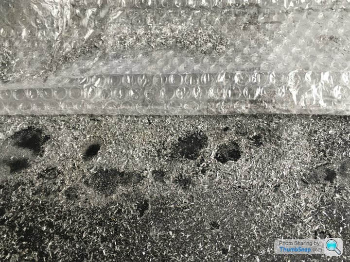
You’ll recall that the bores were badly scored by the ceramic “sand” that had worked its way back up the header pipes from the cats:
As standard, the bores of the cast alloy blocks are plated with Nikasil, a nickel/ceramic coating that provides a hard finish for the piston rings to run against. Boring and re-plating/honing would result in oversize bores, and oversize pistons aren’t available. So the options were a new block, or a sleeved one. The latter would be a £2k saving and would result in a harder-wearing finish. There were no obvious advantages to having a new block for me, so we decided to machine the old one.
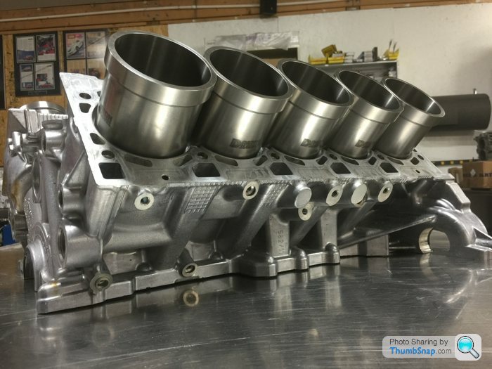
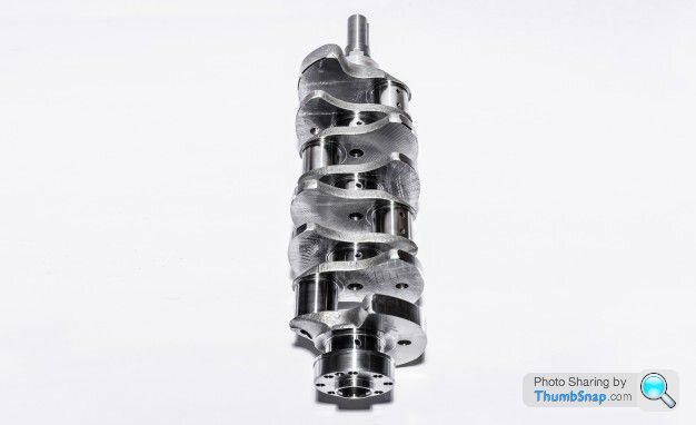
The steel liners came from L.A. Sleeve of Santa Fe, Ca. and are flanged. That is to say that for most of their length, they are a thin-walled steel tube, but towards the top, cylinder head-end, they are much thicker-walled. Therefore they are much more positively seated than a sleeve without a flange. The bores are rebored to the outside diameter of the sleeve, and then counter-bored to the diameter and depth of the flange, before the deck is skimmed flat. With the head torqued down the flange is pressed firmly into its seat. This isn’t my block, nor L.A. Sleeve liners, but I’m sure mine looked very similar:
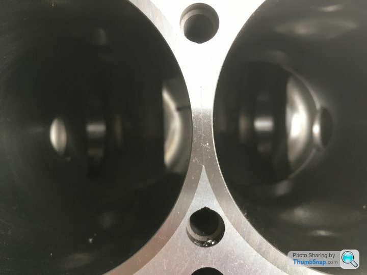
In the following pictures it appears that the bores have become Siamesed, and indeed they have, but only to the depth of the flange. Lower down, the alloy webs remain between the cylinders (and this IS my block):

Lower down in the bores, the liners have “windage” holes drilled through them, and this is a convenient time to show you one of the numerous differences between the 5.0 and 5.2 litre blocks. (Remember that the two V10 units (Lambo’s 5 and Audi’s 5.2) were developed separately from related, but different, 4 and 4.2 litre V8s.)
Here is an end shot of a (later) 5.2 litre block:
And my (earlier) 5.0 litre block
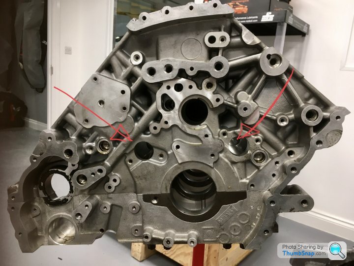
Note the two extra holes in the earlier block. These are the windage holes and pass through the lower end of each cylinder for the entire length of each bank. As the pistons thrash up and down, the air in the volumes below them is repeatedly being compressed and expanded. In the earlier engine, these pressure changes are alleviated and reduced by the air being allowed to pass from one bore to the next through the windage holes (in addition to it passing under the base of each bore). This extra alleviation of the pressure changes wasn’t needed in the later engines due to the increased efficiency of the oil scavenge pump fitted to the latter. Of much greater power (six chambers rather than three?) it can pump oil from the dry sump back to the oil tank at a much greater rate. Therefore the oil is less likely to become aerated in the short time that it spends under the thrashing pistons, and so there is less need to reduce the air pressure differences with the later oil pump.
Who knew? (Well, Ricky for one!)
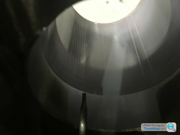
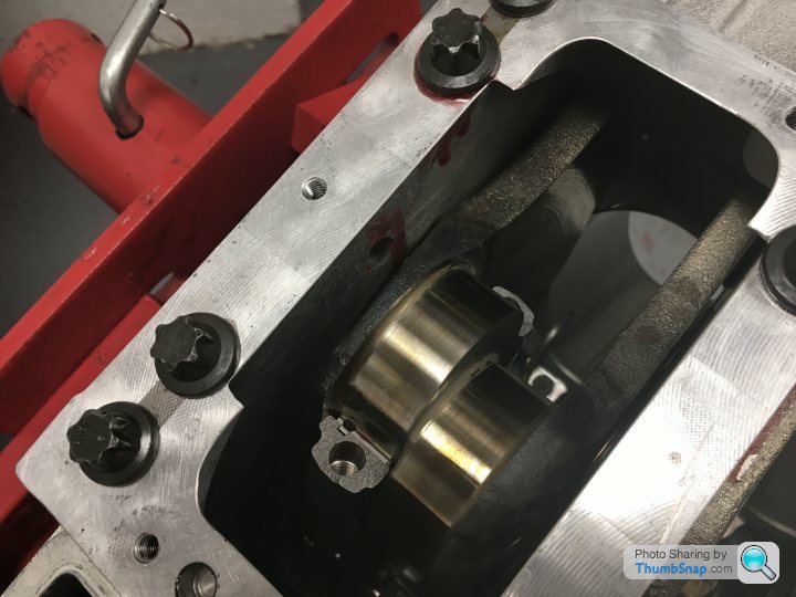
Anyway, here is one of the windage holes in a cylinder sleeve, as seen down one of the bores of my block:
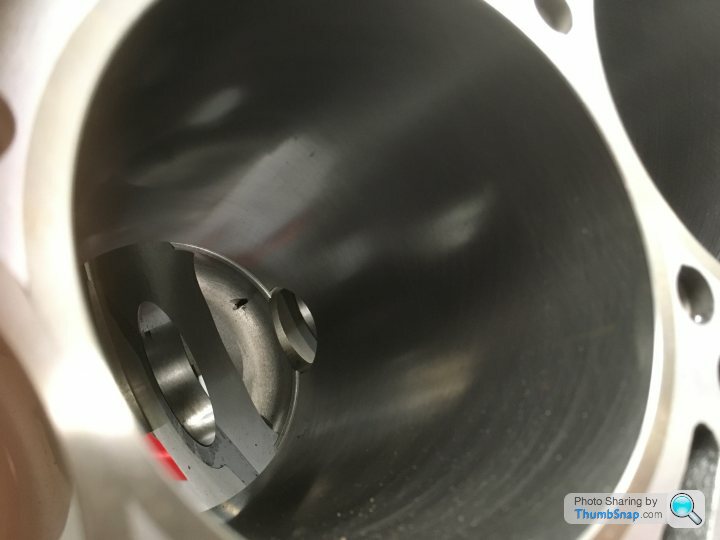
(I should add that all of the shots of my block were taken shortly after it arrived back from the machinist. Ricky had been measuring up for the crank shell sizes and then it was going into his parts cleaning tank for several hours. That should have shifted not only the swarf in the galleries, but the dead flies too!!)
With the sleeves machined into place, they then have to be honed to size and shape. And it was this process that led to the biggest delay in the machining process. Because, in all of the photos of my block above, the bore is the wrong shape!!
When you torque down the cylinder head onto the block, it distorts the block itself. (And indeed, how the block is distorted depends on whether the head is held down by studs or bolts, the former squashing the top of the block, the latter the bottom.) As you look at the photos above, the bores are not round! They will only become so again when the cylinder heads are torqued down onto them. Therefore, before the cylinder liners can be honed to size, the block has to be distorted in exactly the same way as if the heads were in place and torqued down.
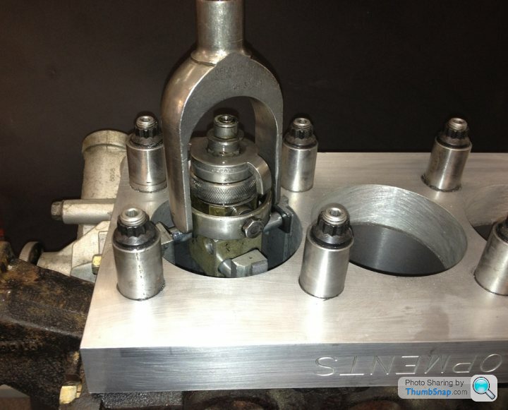
This is achieved by the use of “Torque Plates”. These are THICK metal plates that are bolted down onto the block in exactly the same way as the cylinder heads are (either studs or bolts) and to the same torque, but with large holes in them allowing the honing tool to pass through them. The machinists “had” them, but couldn’t find them! Ricky has his own, but they were apparently too deep for the machine shop. So they had to make up a new set.......
Here’s a picture of a bore being honed (again, not my engine). The torque plate is a thick metal plate, but not as thick as the actual cylinder head casting. So here extension tubes have been machined to allow the actual head studs to be used. The honing tool is four abrasive pads held against the cylinder walls by spring pressure:
Next time......... Con rods!! (Trust me; it’s genuinely interesting!!)
You’ll recall that the bores were badly scored by the ceramic “sand” that had worked its way back up the header pipes from the cats:
As standard, the bores of the cast alloy blocks are plated with Nikasil, a nickel/ceramic coating that provides a hard finish for the piston rings to run against. Boring and re-plating/honing would result in oversize bores, and oversize pistons aren’t available. So the options were a new block, or a sleeved one. The latter would be a £2k saving and would result in a harder-wearing finish. There were no obvious advantages to having a new block for me, so we decided to machine the old one.
The steel liners came from L.A. Sleeve of Santa Fe, Ca. and are flanged. That is to say that for most of their length, they are a thin-walled steel tube, but towards the top, cylinder head-end, they are much thicker-walled. Therefore they are much more positively seated than a sleeve without a flange. The bores are rebored to the outside diameter of the sleeve, and then counter-bored to the diameter and depth of the flange, before the deck is skimmed flat. With the head torqued down the flange is pressed firmly into its seat. This isn’t my block, nor L.A. Sleeve liners, but I’m sure mine looked very similar:
In the following pictures it appears that the bores have become Siamesed, and indeed they have, but only to the depth of the flange. Lower down, the alloy webs remain between the cylinders (and this IS my block):
Lower down in the bores, the liners have “windage” holes drilled through them, and this is a convenient time to show you one of the numerous differences between the 5.0 and 5.2 litre blocks. (Remember that the two V10 units (Lambo’s 5 and Audi’s 5.2) were developed separately from related, but different, 4 and 4.2 litre V8s.)
Here is an end shot of a (later) 5.2 litre block:
And my (earlier) 5.0 litre block
Note the two extra holes in the earlier block. These are the windage holes and pass through the lower end of each cylinder for the entire length of each bank. As the pistons thrash up and down, the air in the volumes below them is repeatedly being compressed and expanded. In the earlier engine, these pressure changes are alleviated and reduced by the air being allowed to pass from one bore to the next through the windage holes (in addition to it passing under the base of each bore). This extra alleviation of the pressure changes wasn’t needed in the later engines due to the increased efficiency of the oil scavenge pump fitted to the latter. Of much greater power (six chambers rather than three?) it can pump oil from the dry sump back to the oil tank at a much greater rate. Therefore the oil is less likely to become aerated in the short time that it spends under the thrashing pistons, and so there is less need to reduce the air pressure differences with the later oil pump.
Who knew? (Well, Ricky for one!)
Anyway, here is one of the windage holes in a cylinder sleeve, as seen down one of the bores of my block:
(I should add that all of the shots of my block were taken shortly after it arrived back from the machinist. Ricky had been measuring up for the crank shell sizes and then it was going into his parts cleaning tank for several hours. That should have shifted not only the swarf in the galleries, but the dead flies too!!)
With the sleeves machined into place, they then have to be honed to size and shape. And it was this process that led to the biggest delay in the machining process. Because, in all of the photos of my block above, the bore is the wrong shape!!
When you torque down the cylinder head onto the block, it distorts the block itself. (And indeed, how the block is distorted depends on whether the head is held down by studs or bolts, the former squashing the top of the block, the latter the bottom.) As you look at the photos above, the bores are not round! They will only become so again when the cylinder heads are torqued down onto them. Therefore, before the cylinder liners can be honed to size, the block has to be distorted in exactly the same way as if the heads were in place and torqued down.
This is achieved by the use of “Torque Plates”. These are THICK metal plates that are bolted down onto the block in exactly the same way as the cylinder heads are (either studs or bolts) and to the same torque, but with large holes in them allowing the honing tool to pass through them. The machinists “had” them, but couldn’t find them! Ricky has his own, but they were apparently too deep for the machine shop. So they had to make up a new set.......
Here’s a picture of a bore being honed (again, not my engine). The torque plate is a thick metal plate, but not as thick as the actual cylinder head casting. So here extension tubes have been machined to allow the actual head studs to be used. The honing tool is four abrasive pads held against the cylinder walls by spring pressure:
Next time......... Con rods!! (Trust me; it’s genuinely interesting!!)
Edited by 4321go on Sunday 11th August 21:44
Swampy1982 said:
....... however, a key detail is missing...
Hows the focus?
Unlike Italian exotica, which require almost constant, expensive fettling (and don’t believe those that say otherwise; if you USE these cars, they cost money!), the only failure in 8,000 miles has been a power-steering pump pressure switch; about £50.Hows the focus?
There are better examples out there. The suspension bushes are worn (it sometimes lurches a bit during cornering) and it could really do with a new cat. But you can pedal flat-out everywhere without fear of losing your license.
I worry that when the MoT is due in November, it won’t be economically viable to get it through. In which case I’ll scrap it and buy another as it’s been quite liberating to have a “normal” car, for trips to the “big” Tesco and the tip!!
yzr500 said:
Interesting but a few questions ,would the new piston clearance within the bores be different between Nikasil / iron sleeves ? also the new pistons would have the rings suitable for Nikasil not iron sleeves .
I’d have to ask Ricky for a definitive answer, but my own thoughts on it are that it goes the other way around. That is to say that the Nikasil process is designed to give the bores of an alloy block the same hardness and wear resistance as steel, and to interact with the spring steel of the rings accordingly, rather than the rings needing to be compatible with the Nikasil. As for the clearances, I’m pretty confident that they’d be honed to the same sizes as OEM; it’s the expanding rings that form the gas seal.Besides, we’re using the CP Carrillo aftermarket pistons and rings...... (remember, they’re probably better, certainly lighter and around £2800 rather than £14,000!).
Thanks chaps!
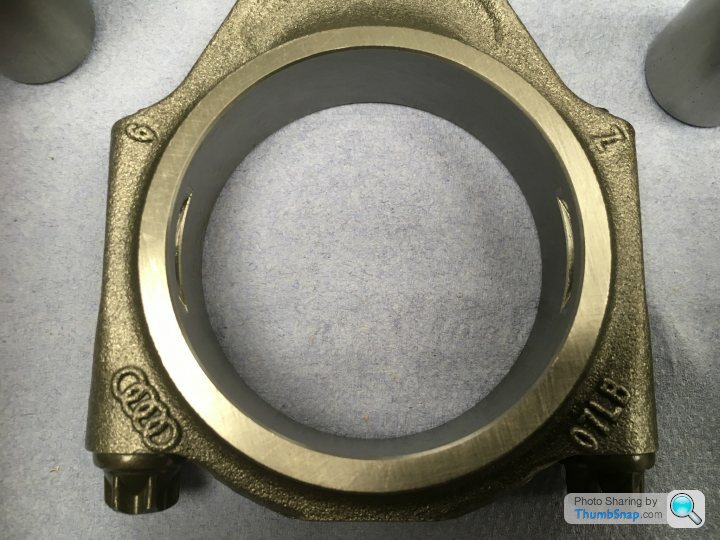
So firstly, how do you make a connecting rod?:
Cast/forge/sinter your rod. Machine the hole in the little end and press in your bushing. Drill your two holes in the big end for the con-rod bolts. Maybe tap these holes too. Now cut the big end in half. The hole for your crank pin will no longer be round, but this isn’t really very important at this stage. Take the rod and it’s end cap and machine their mating surfaces to accept a collet to ensure that when they are joined together, there is no possibility of the two pieces moving relative to one another. Now join them back together and torque-up the con rod bolts. Finally, machine the big-end hole to the correct, round size.
Here’s the finished big end of a connecting rod. It happens to be a CP Carrillo rod for a 5.2 litre, forced induction build of Ricky’s:

I had the choice of Carrillo rods to match the pistons (circa £2800 IIRC) or OEM Audi rods (£1100). The Carrillo rods are perfectly machined things of beauty and it was tempting to spend the extra. But my engine doesn’t need them. They’re a must to contain the extreme forces generated by forced induction; a supercharger or twin-turbo conversion. But the Audi rods are easily good enough for my (relatively) standard build. Besides, the Audi rods are considerably lighter. As are the CP Carrillo gudgeon pins to suit. For forced induction engines, they produce a machine-steel pin, with massively thick walls and a narrow hole down the centre. For a NA engine, we’re still using Carrillo gudgeon pins because we’re using Carrillo pistons, but they’re of a similar wall thickness as the OEM Audi pins. So we’re using the lightest piston/gudgeon pin/con-rod combination available. Good-oh!
But onto those Audi connecting rods. What’s missing from this picture?
That’s right! There’s apparently no break in the big end!! How the hell do you install the bearing shells and clamp it around the crank pin?
And here’s where the economies of scale between an OE manufacturer and an aftermarket manufacturer show. CP Carrillo have to manufacture their rods in something like the fashion that I described above, although I probably missed out several hardening and machining steps. The Audi rods, in comparison, are “cracked”!
Their manufacturing process reads something like this:
Forge rod. Machine little end and press in bush. Drill and tap big end for the con-rod bolts and install said bolts. Machine hole for crank pin in big end. FREEZE the whole rod in liquid nitrogen. Hit with lump hammer.........
Yup, in that photo above, the big end is cracked in half at a crystalline level! And until you undo the con-rod bolts for the first time, you’ll never see the break. And when you’ve fitted the bearing shells and come to join the two halves back together again, they marry perfectly. Every time. And the mating faces can’t possible move relative to one another. So the big-end hole will be perfectly aligned. Every time!
I know! Genius, isn’t it!!!
Here are some shots of one of my rods that has been undone:
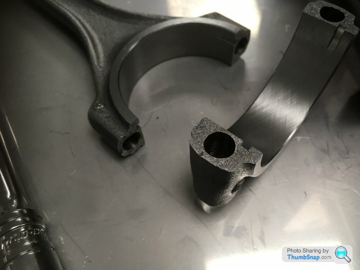
And here are the two end caps; CP Carrillo (with its machined-in collets) in the foreground, the unique crystalline face of the Audi “cracked rod” in the background:
And the rod married whole again. Torque-up the con-rod bolts (they haven’t been here) and that visible crack will be all-but invisible again:
Mind blowing!
So firstly, how do you make a connecting rod?:
Cast/forge/sinter your rod. Machine the hole in the little end and press in your bushing. Drill your two holes in the big end for the con-rod bolts. Maybe tap these holes too. Now cut the big end in half. The hole for your crank pin will no longer be round, but this isn’t really very important at this stage. Take the rod and it’s end cap and machine their mating surfaces to accept a collet to ensure that when they are joined together, there is no possibility of the two pieces moving relative to one another. Now join them back together and torque-up the con rod bolts. Finally, machine the big-end hole to the correct, round size.
Here’s the finished big end of a connecting rod. It happens to be a CP Carrillo rod for a 5.2 litre, forced induction build of Ricky’s:
I had the choice of Carrillo rods to match the pistons (circa £2800 IIRC) or OEM Audi rods (£1100). The Carrillo rods are perfectly machined things of beauty and it was tempting to spend the extra. But my engine doesn’t need them. They’re a must to contain the extreme forces generated by forced induction; a supercharger or twin-turbo conversion. But the Audi rods are easily good enough for my (relatively) standard build. Besides, the Audi rods are considerably lighter. As are the CP Carrillo gudgeon pins to suit. For forced induction engines, they produce a machine-steel pin, with massively thick walls and a narrow hole down the centre. For a NA engine, we’re still using Carrillo gudgeon pins because we’re using Carrillo pistons, but they’re of a similar wall thickness as the OEM Audi pins. So we’re using the lightest piston/gudgeon pin/con-rod combination available. Good-oh!
But onto those Audi connecting rods. What’s missing from this picture?
That’s right! There’s apparently no break in the big end!! How the hell do you install the bearing shells and clamp it around the crank pin?
And here’s where the economies of scale between an OE manufacturer and an aftermarket manufacturer show. CP Carrillo have to manufacture their rods in something like the fashion that I described above, although I probably missed out several hardening and machining steps. The Audi rods, in comparison, are “cracked”!
Their manufacturing process reads something like this:
Forge rod. Machine little end and press in bush. Drill and tap big end for the con-rod bolts and install said bolts. Machine hole for crank pin in big end. FREEZE the whole rod in liquid nitrogen. Hit with lump hammer.........
Yup, in that photo above, the big end is cracked in half at a crystalline level! And until you undo the con-rod bolts for the first time, you’ll never see the break. And when you’ve fitted the bearing shells and come to join the two halves back together again, they marry perfectly. Every time. And the mating faces can’t possible move relative to one another. So the big-end hole will be perfectly aligned. Every time!
I know! Genius, isn’t it!!!
Here are some shots of one of my rods that has been undone:
And here are the two end caps; CP Carrillo (with its machined-in collets) in the foreground, the unique crystalline face of the Audi “cracked rod” in the background:
And the rod married whole again. Torque-up the con-rod bolts (they haven’t been here) and that visible crack will be all-but invisible again:
Mind blowing!
wilksy61 said:
however could I just make a point regarding the honing process
I’m an airline pilot. Whilst I can attack an old-tech British Classic with a spanner, there’s absolutely NO guarantee that it won’t result in a stripped thread!!I positively welcome being corrected and would encourage contributions from the experts as we go along.....
Ha! Yup, that’s me. Well sleuthed!
The clutch and release bearing were replaced about 5000 miles ago. I avoid full-bore standing starts, short-shift around second and double declutch all of my gear changes. So the last clutch lasted over 60,000 miles! As for the exhaust system, I failed to buy a pair of beautiful looking, German manufactured, stainless steel tubular headers on fleabay a few years ago (cheap at £2000 IIRC) so the originals will go back on. With decat pipes and an original OEM Superleggera system (a super-lucky eBay gamble, hardly used and £155!!), it’s pretty free-flowing and sounds incredible.
And talking of sound........
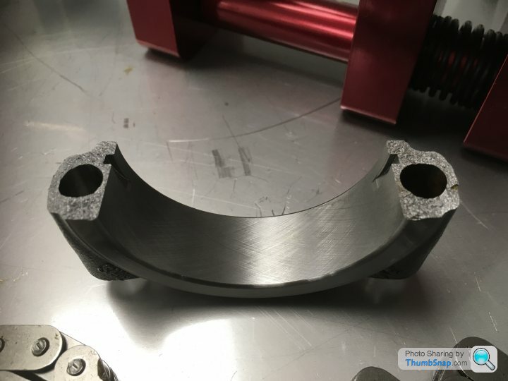
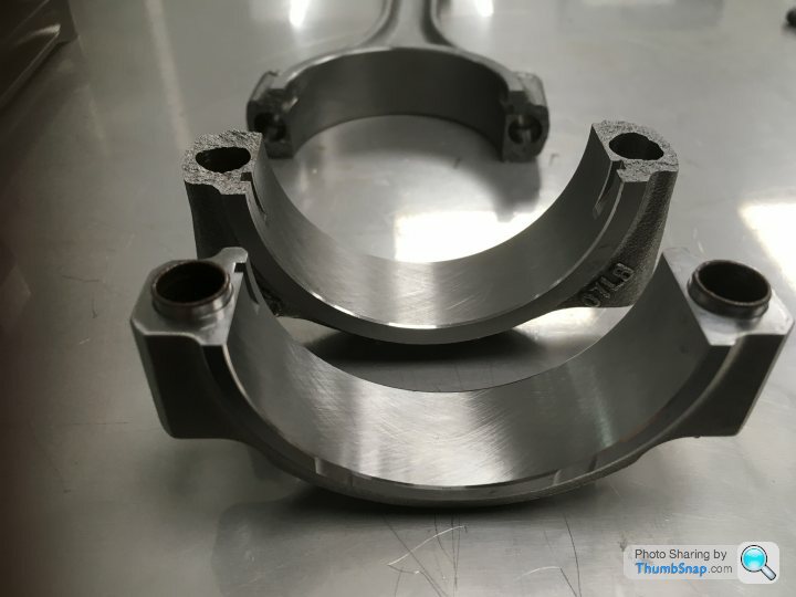
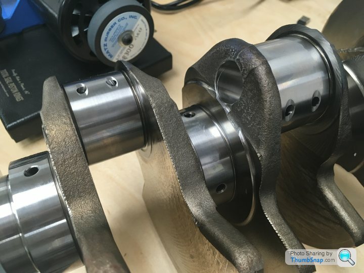
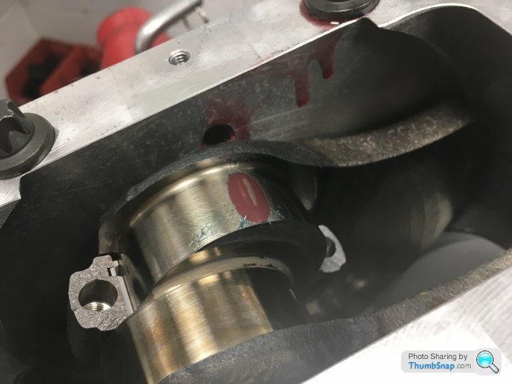
It’s often noted that the 5.0 litre Gallardo engine is one of the best sounding out there. It’s generally agreed that it’s much better sounding than the replacement 5.2 litre LP-series engines. And that’s down to the crank. On any V engine, two con rods sit together on a journal between a pair of crank webs. On the later engine, that journal is a straight one; the pairs of con rods sit side-by-side. But on the earlier engines, the journals are staggered. Which subtly alters the firing angle and hence the sound of the engine. As ever, much easier to illustrate with photos:
My crank, with the staggered journals between the webs (and note crystalline face of one of those fractured rods going into place):
And a later 5.2 engine, with straight journals:
The first photo suggests that my engine is finally coming together again. And it is!
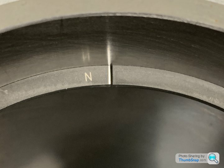
All of the rings have been individually gapped:
And as each component is assembled, Ricky initially does so without any build lube, instead using plastigauge to check that the tolerances that he’s previously calculated by exacting measurements are indeed as expected:
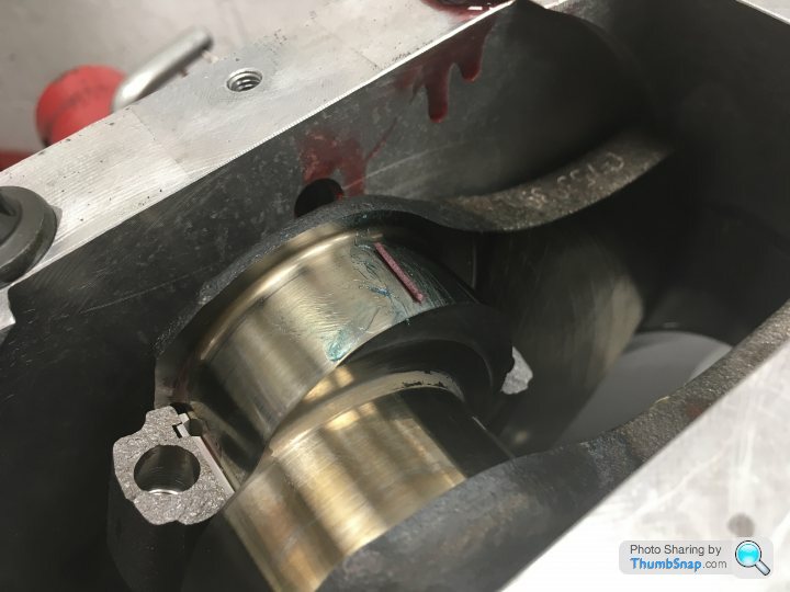
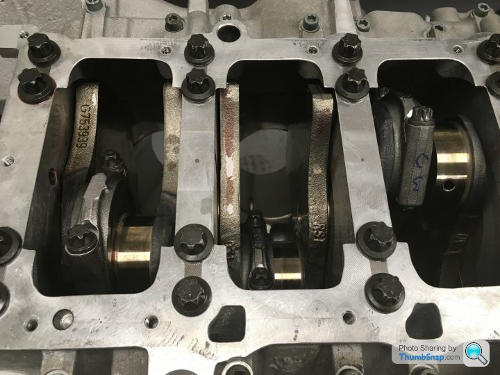
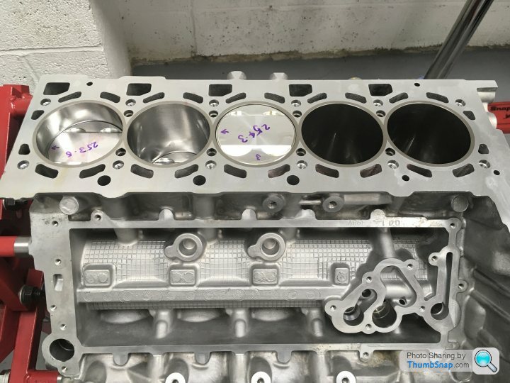
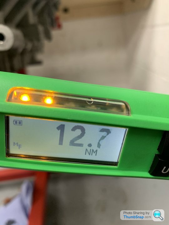
A time-consuming process, and not a level of detail that is bothered with when the engines are originally slapped together on the line, but the results speak for themselves. With the crank and all ten pistons installed, the breakaway torque, the force needed to spin the crank (clamped tightly within the block), all ten con rods (clamped around the crank) and run thirty piston rings up and down the cross-honed bores, is less than 13 Nm. For the non-mechanically minded, that’s an impressively small number!
The clutch and release bearing were replaced about 5000 miles ago. I avoid full-bore standing starts, short-shift around second and double declutch all of my gear changes. So the last clutch lasted over 60,000 miles! As for the exhaust system, I failed to buy a pair of beautiful looking, German manufactured, stainless steel tubular headers on fleabay a few years ago (cheap at £2000 IIRC) so the originals will go back on. With decat pipes and an original OEM Superleggera system (a super-lucky eBay gamble, hardly used and £155!!), it’s pretty free-flowing and sounds incredible.
And talking of sound........
It’s often noted that the 5.0 litre Gallardo engine is one of the best sounding out there. It’s generally agreed that it’s much better sounding than the replacement 5.2 litre LP-series engines. And that’s down to the crank. On any V engine, two con rods sit together on a journal between a pair of crank webs. On the later engine, that journal is a straight one; the pairs of con rods sit side-by-side. But on the earlier engines, the journals are staggered. Which subtly alters the firing angle and hence the sound of the engine. As ever, much easier to illustrate with photos:
My crank, with the staggered journals between the webs (and note crystalline face of one of those fractured rods going into place):
And a later 5.2 engine, with straight journals:
The first photo suggests that my engine is finally coming together again. And it is!
All of the rings have been individually gapped:
And as each component is assembled, Ricky initially does so without any build lube, instead using plastigauge to check that the tolerances that he’s previously calculated by exacting measurements are indeed as expected:
A time-consuming process, and not a level of detail that is bothered with when the engines are originally slapped together on the line, but the results speak for themselves. With the crank and all ten pistons installed, the breakaway torque, the force needed to spin the crank (clamped tightly within the block), all ten con rods (clamped around the crank) and run thirty piston rings up and down the cross-honed bores, is less than 13 Nm. For the non-mechanically minded, that’s an impressively small number!
Neither engine has a flat-plane crank. A flat-plane crank has the crank throws at 180°, like this, from the Shelby GT350
The split crankpins of the 5.0 results in an even firing order, one cylinder firing every 72° of crank rotation.
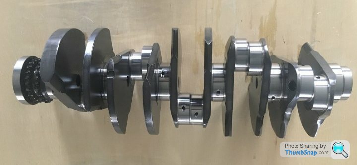
The shared crankpins of the 5.2 apparently results in an uneven firing order, every 54° or 90°.
Apparently.
The split crankpins of the 5.0 results in an even firing order, one cylinder firing every 72° of crank rotation.
The shared crankpins of the 5.2 apparently results in an uneven firing order, every 54° or 90°.
Apparently.
Thank you for showing an interest!
I’d love to say “Yes!” but, er.......... “No!”
The engine IS now complete. As in... “Today”! Ancillaries will go on soon. The oil pump has been stripped, inspected and rebuilt (a relief as a new one is circa £4000!). We need to source a new aircon pump. The rear anti-roll bar and exhaust tip grills are away being powder coated, which I think are the last pieces needing this.
I’ll write a piece on the cylinder head work soon (new valve guides, new valve seats recut with 3 angle valve seating rather than 2, new aftermarket valves with Inconel exhaust valves rather than sodium-filled stainless steel, ported inlet and exhaust tracts). I need to tap Ricky up for some photos he took whilst he was doing the work.
But.....
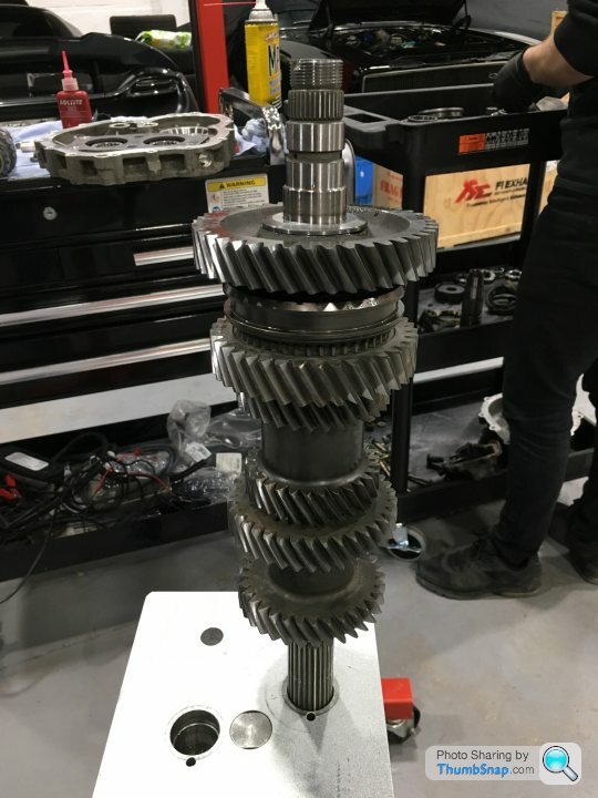
The gearbox is now also in pieces!! I’ve always shifted around a bolshie second gear. It was always usable, but not great. And as Ricky seems to have as many dismantled ‘boxes on site as engines, it made sense to have mine inspected now.
Seems that I could possibly get away with just replacing the 1/2 synchro rings. But to do it right, second gear needs replacing too. And, although I’ve never experienced any problems with third, Ricky showed me the incipient wear on the third-gear wheel and the 3/4 synchro rings. It’d go the same way as second eventually, so we’re replacing them too. And of course, the ‘box is unique to the pre-LP cars and the internals can’t be replaced with the cheaper Audi parts from the later ‘boxes.
So, for those that like them, there’ll be many more updates and photos to come.
Bugger!
I’d love to say “Yes!” but, er.......... “No!”
The engine IS now complete. As in... “Today”! Ancillaries will go on soon. The oil pump has been stripped, inspected and rebuilt (a relief as a new one is circa £4000!). We need to source a new aircon pump. The rear anti-roll bar and exhaust tip grills are away being powder coated, which I think are the last pieces needing this.
I’ll write a piece on the cylinder head work soon (new valve guides, new valve seats recut with 3 angle valve seating rather than 2, new aftermarket valves with Inconel exhaust valves rather than sodium-filled stainless steel, ported inlet and exhaust tracts). I need to tap Ricky up for some photos he took whilst he was doing the work.
But.....
The gearbox is now also in pieces!! I’ve always shifted around a bolshie second gear. It was always usable, but not great. And as Ricky seems to have as many dismantled ‘boxes on site as engines, it made sense to have mine inspected now.
Seems that I could possibly get away with just replacing the 1/2 synchro rings. But to do it right, second gear needs replacing too. And, although I’ve never experienced any problems with third, Ricky showed me the incipient wear on the third-gear wheel and the 3/4 synchro rings. It’d go the same way as second eventually, so we’re replacing them too. And of course, the ‘box is unique to the pre-LP cars and the internals can’t be replaced with the cheaper Audi parts from the later ‘boxes.
So, for those that like them, there’ll be many more updates and photos to come.
Bugger!
I’ll start with my apologies for not having updated this thread for so long. Sorry!
Where were we? Ah yes! Cylinder heads.
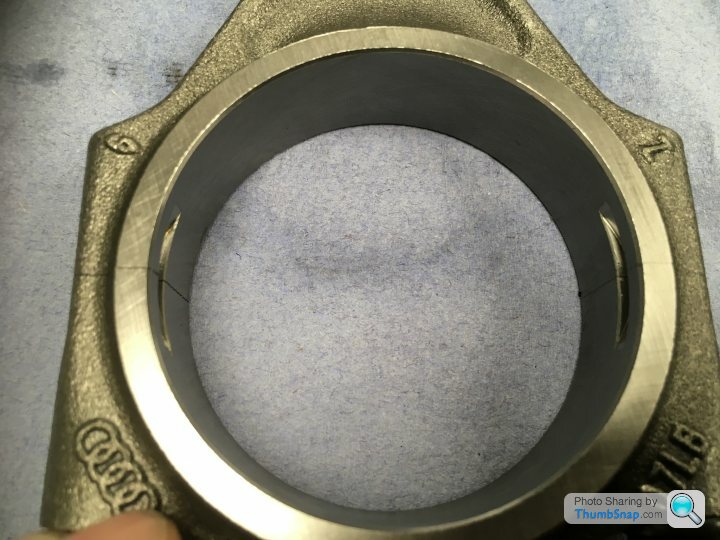
I suppose we could have just bolted the heads straight back onto the refinished block. But, after 14 years and 106,000 miles, there was certainly enough wear evident to justify their rebuild. Again, any mistakes in the following are my own! It went something like this:
The worn valve guides and seats were pressed or reamed out of the alloy heads before being replaced with new, unworn items. I’ve made that sound very simple and I know that it isn’t. I’d love to be able to tell you exactly how the process went. Were the old valve seats simply drifted out from behind (there’s a lip, accessible from the inlet and exhaust tracts that allows this, but risks damaging the head), maybe after having heated the head in an oven? Or were the old seats reamed away until all that was left simply fell out? Both are possible methods. But all of the machining of the heads was carried out by the same (extremely competent and reputable!) engine machine shop that “did” the block, so I was blind to the process.
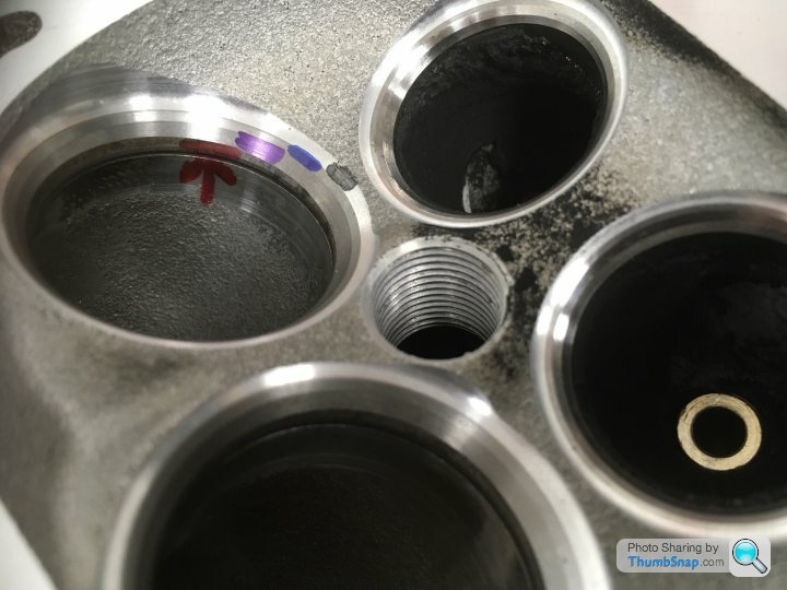
Next, the new valve seats were cut to shape. This is critical! The valves MUST seat perfectly. At 7000rpm, the valves are slamming back onto their seats 60 times PER SECOND. If the seats aren’t perfectly positioned and cut then the valve’s head will flex on the stem and metal fatigue will see the valve break in very little time. The shape of the finished valve seat is also very important. The gasses transition from (inlet) or to (exhaust) a linear flow through the narrow gap between the valve and the seat.
The ideal is a radius cut, the seat being cut to a curved profile, exactly matching the radius of the curve of the transition of the valve from stem to head. However, this is only used in racing applications as the seats subsequently wear at a very fast rate. (No, I don’t know why! It seams counterintuitive to me?) The factory cut the seats at two angles, which isn’t bad. The seats in my engine have been cut at three angles, which will greatly improve the gas flow both into and out of the cylinders. The valves actually seat on the middle of the three angled cuts. The more narrow this land, the more power that you’ll potentially be able to generate, but also the quicker the wear of the seat. In race-engine terms, the 1.1mm central land of my valve seats is apparently huge! But this is a road car and requires decent longevity.
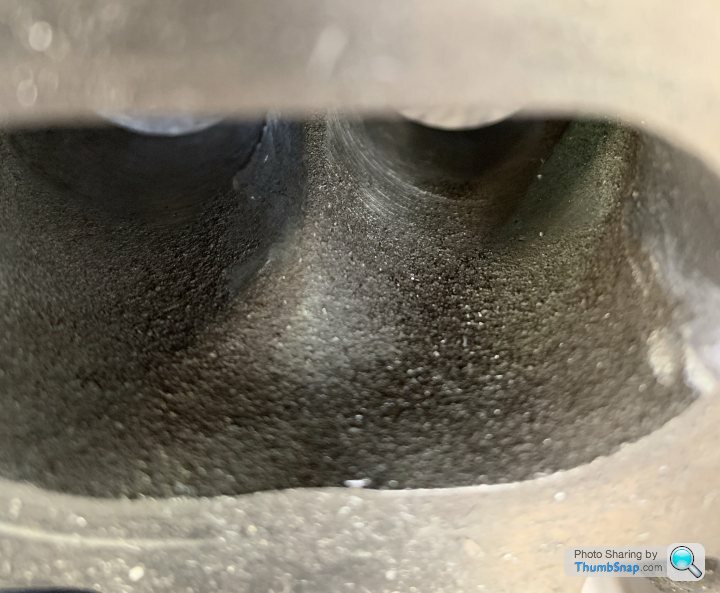
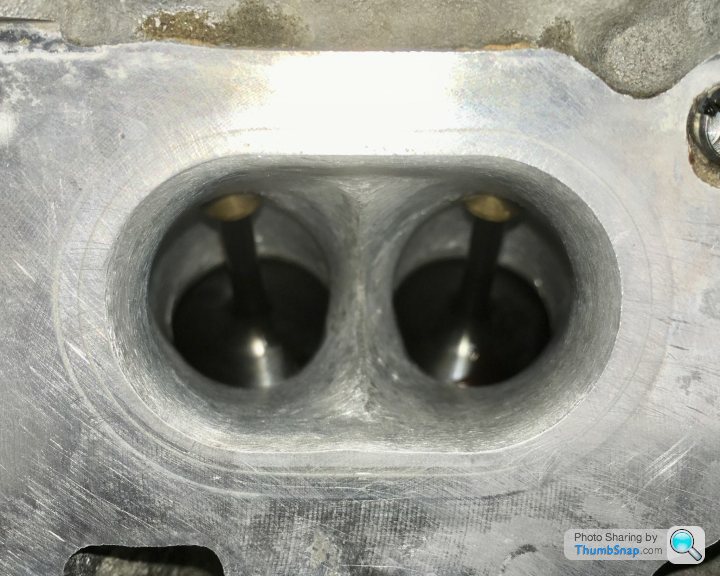
The following photographs show the refinished heads as Ricky received them back from the machine shop, and before he did any subsequent work on them. The marked-up valve seat is an inlet. The black, blue and purple Sharpie marks delineate the three angles cut into the valve seat. The blue line is the 1.1mm wide land that the valve actually seats onto. Note also the nasty (red) step and the sand cast finish of the inlet tract. The exhaust tract is exactly the same under its coat of soot!
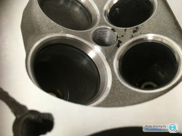
With the re-machined heads back in-house, Ricky ported both the inlet and exhaust tracts. The factory undertake no porting work whatsoever, the tracts retaining the exact shape and sand-cast finish that they left the foundry with.
With rotary porting files, Ricky removed a sizeable amount of metal from the inlet tracts’ walls, making a straighter line from plenum to valve (and hence, hopefully a more linear flow). He also “knife-edged” the previously rather blunt and sloppy (slopie?) part of the casting where each inlet tract bifurcates to accommodate the two inlet valves.
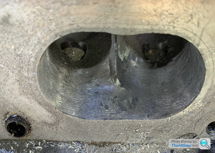
(Neither of the last two photos show the final finish!)
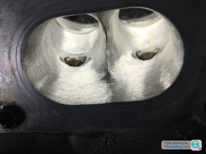
The exhaust tracts required the removal of less metal, but there was scope for the improvement of the gas flows there too. Finally, he surface-finished the tracts to a level resembling brushed aluminium, a massive improvement over the original, sand-cast finish.
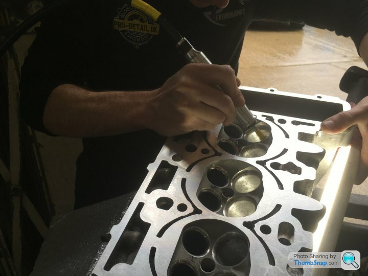
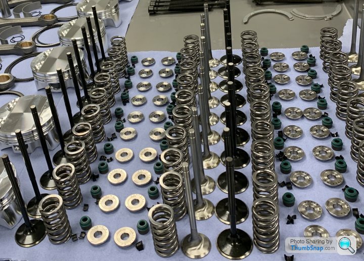
Machined and ported (and after MANY passes through he parts washer!) the heads were reassembled. The entire valve train is a kit from Supertech in California ( supertechperformance.com ). This is because a modern racing supplier is able to supply much improved items for a similar price to the twenty-year-old tech of the OEM. The inlet valves are similar to OE, being simple stainless steel valves, but the final “Black Nitride” coating results in a much smoother valve, again improving gas flow. The stock exhaust valves are stainless steel and sodium-filled for heat dissipation. The Supertech exhaust valves are also sodium filled, but the valve itself is forged from Inconel (a nickel alloy), resulting in a much lighter valve. The Supertech kit also includes titanium collets (again, for lightness; important when the valves are reciprocating at over 60Hz) and updated valve springs (providing more positive control of the valves over the OE springs).
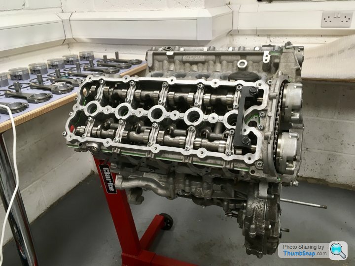
The rebuilt heads were then reattached to the block and torqued down. As this is a normally aspirated engine, stock head bolts were used, there being no need to use the updated bolts that Ricky would use in a forced induction application.
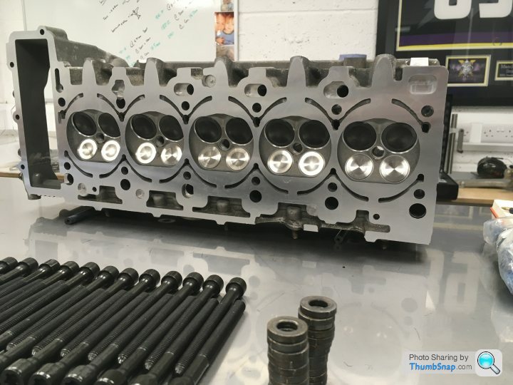
The stock camshafts were then reinstalled, followed by new timing chains and chain guides and tensioners.
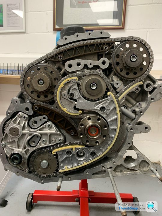
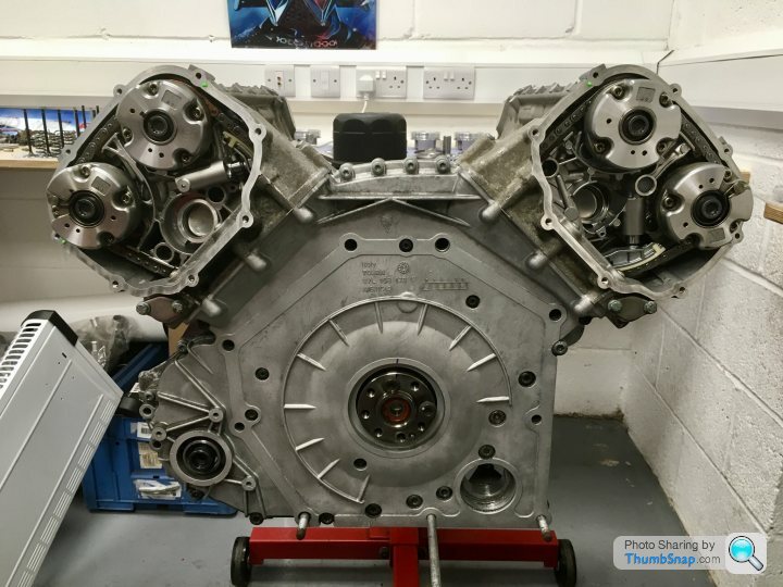
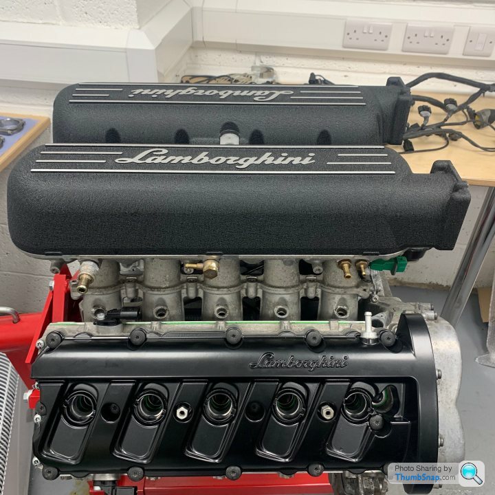
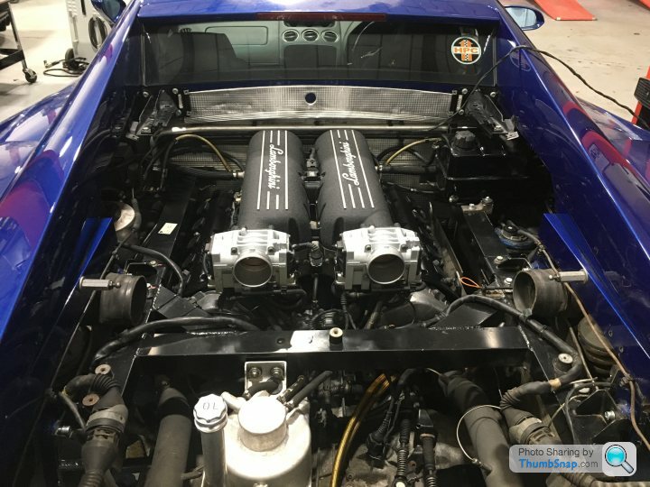
Finally, the intake plenum/throttle body unit was mounted in the vee and the basic engine was closed up with its refinished (powder coated) cam covers and plenum cover.
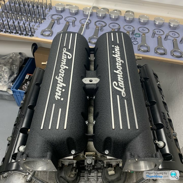
Hoorah!!
Next.......... Engine ancillaries.
Where were we? Ah yes! Cylinder heads.
I suppose we could have just bolted the heads straight back onto the refinished block. But, after 14 years and 106,000 miles, there was certainly enough wear evident to justify their rebuild. Again, any mistakes in the following are my own! It went something like this:
The worn valve guides and seats were pressed or reamed out of the alloy heads before being replaced with new, unworn items. I’ve made that sound very simple and I know that it isn’t. I’d love to be able to tell you exactly how the process went. Were the old valve seats simply drifted out from behind (there’s a lip, accessible from the inlet and exhaust tracts that allows this, but risks damaging the head), maybe after having heated the head in an oven? Or were the old seats reamed away until all that was left simply fell out? Both are possible methods. But all of the machining of the heads was carried out by the same (extremely competent and reputable!) engine machine shop that “did” the block, so I was blind to the process.
Next, the new valve seats were cut to shape. This is critical! The valves MUST seat perfectly. At 7000rpm, the valves are slamming back onto their seats 60 times PER SECOND. If the seats aren’t perfectly positioned and cut then the valve’s head will flex on the stem and metal fatigue will see the valve break in very little time. The shape of the finished valve seat is also very important. The gasses transition from (inlet) or to (exhaust) a linear flow through the narrow gap between the valve and the seat.
The ideal is a radius cut, the seat being cut to a curved profile, exactly matching the radius of the curve of the transition of the valve from stem to head. However, this is only used in racing applications as the seats subsequently wear at a very fast rate. (No, I don’t know why! It seams counterintuitive to me?) The factory cut the seats at two angles, which isn’t bad. The seats in my engine have been cut at three angles, which will greatly improve the gas flow both into and out of the cylinders. The valves actually seat on the middle of the three angled cuts. The more narrow this land, the more power that you’ll potentially be able to generate, but also the quicker the wear of the seat. In race-engine terms, the 1.1mm central land of my valve seats is apparently huge! But this is a road car and requires decent longevity.
The following photographs show the refinished heads as Ricky received them back from the machine shop, and before he did any subsequent work on them. The marked-up valve seat is an inlet. The black, blue and purple Sharpie marks delineate the three angles cut into the valve seat. The blue line is the 1.1mm wide land that the valve actually seats onto. Note also the nasty (red) step and the sand cast finish of the inlet tract. The exhaust tract is exactly the same under its coat of soot!
With the re-machined heads back in-house, Ricky ported both the inlet and exhaust tracts. The factory undertake no porting work whatsoever, the tracts retaining the exact shape and sand-cast finish that they left the foundry with.
With rotary porting files, Ricky removed a sizeable amount of metal from the inlet tracts’ walls, making a straighter line from plenum to valve (and hence, hopefully a more linear flow). He also “knife-edged” the previously rather blunt and sloppy (slopie?) part of the casting where each inlet tract bifurcates to accommodate the two inlet valves.
(Neither of the last two photos show the final finish!)
The exhaust tracts required the removal of less metal, but there was scope for the improvement of the gas flows there too. Finally, he surface-finished the tracts to a level resembling brushed aluminium, a massive improvement over the original, sand-cast finish.
Machined and ported (and after MANY passes through he parts washer!) the heads were reassembled. The entire valve train is a kit from Supertech in California ( supertechperformance.com ). This is because a modern racing supplier is able to supply much improved items for a similar price to the twenty-year-old tech of the OEM. The inlet valves are similar to OE, being simple stainless steel valves, but the final “Black Nitride” coating results in a much smoother valve, again improving gas flow. The stock exhaust valves are stainless steel and sodium-filled for heat dissipation. The Supertech exhaust valves are also sodium filled, but the valve itself is forged from Inconel (a nickel alloy), resulting in a much lighter valve. The Supertech kit also includes titanium collets (again, for lightness; important when the valves are reciprocating at over 60Hz) and updated valve springs (providing more positive control of the valves over the OE springs).
The rebuilt heads were then reattached to the block and torqued down. As this is a normally aspirated engine, stock head bolts were used, there being no need to use the updated bolts that Ricky would use in a forced induction application.
The stock camshafts were then reinstalled, followed by new timing chains and chain guides and tensioners.
Finally, the intake plenum/throttle body unit was mounted in the vee and the basic engine was closed up with its refinished (powder coated) cam covers and plenum cover.
Hoorah!!
Next.......... Engine ancillaries.
A couple of short updates today. I promised “ancillaries”, but first.......
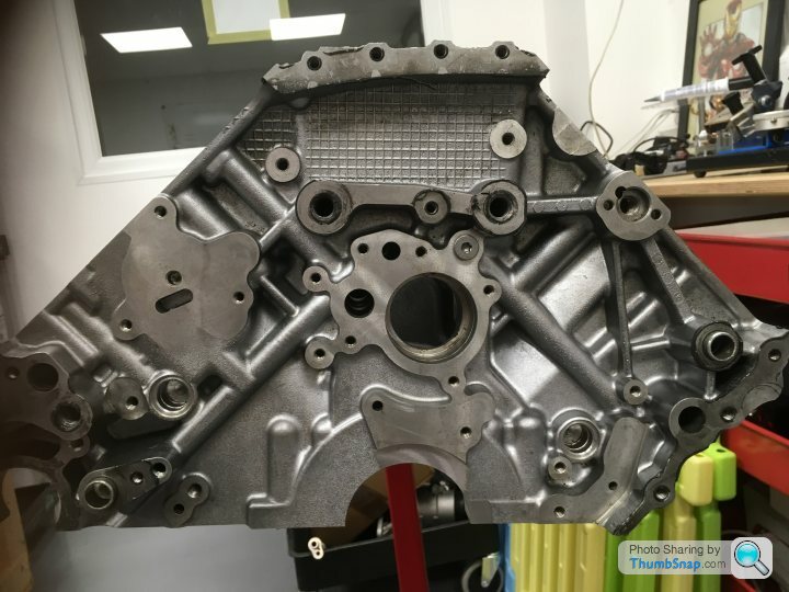
Remember the talk on torque (plates)? Before the cylinder liners are honed to their final finish, thick aluminium plates are bolted down onto the block, deforming it in exactly the same way that the torqued-down cylinder heads do? And that was one of the things that delayed the final finishing of my block; the engineering company doing the machining had to make their own set as Ricky’s extant pair were too deep for their equipment to deal with?
Well, here are the “offending” items. A fairly hefty investment in billet aluminium for what is an uncommon operation on a relatively rare engine!
As for the ancillaries.....
All of the ancillaries are accessible with the engine in situ, so there’s no need to replace any of them as a precaution whilst the engine is out, as is sometimes done with (for example) water pumps when servicing cam belts. And none of the various pumps, etc. are “serviceable” in the conventional sense. Their component pieces aren’t available separately. When they fail, then there’s little option but to replace the whole unit. And we’re talking Lambo prices here! So it’s a case of, “If it ain’t broke, don’t fix it!”
That said......
The water pump was stripped and inspected. There was little wear, so it’s been reassembled and refitted. A new water pump is £684 (inc.)
Same goes for the oil pump (Praise the Lord!!).
If the oil pump fails in a “wet sump” engine then the oil pressure will immediately drop and the red warning light will illuminate on your dash. If you’re sensible and pull over/switch off immediately, then you might get lucky and cause no damage whatsoever! Continue running without oil pressure for a few seconds and you may need a crank grind and new camshafts.
But with a “dry sump” engine two oil pumps are required, although they’re usually combined into the one unit. The “feed” pump feeds the oil galleries with pressurised lubricating oil. Once it’s done it’s lubrication work, the oil falls to the bottom of the engine, from where it is sucked up by the “scavenge” pump (or “pumps”) and returned to the remote oil tank. There is very little volume beneath the crank in which oil can pool. So the scavenge pump must have a higher capacity than the feed pump, to ensure that all of the feed oil is scavenged back to the oil tank and that none remains pooled below crank.
If the scavenge pump fails in a dry sump engine, then in a very short space of time, there will be enough oil accumulated in the bottom of the engine to cause an hydraulic lock. In simple terms, with the pistons thrashing up and down above accumulating oil, sooner rather than later the engine will be trying to compress the incompressible oil. The next event will be catastrophic engine failure. All this goes some way to explaining the cost of a replacement oil pump (that, and the fact that it has a Lamborghini bull cast into it!): £3966 (Yes, you read that right.....)
This (and the cost of a new crank) was one of the reasons why I decided to have my engine rebuilt. Having de-catted it and therefore removed the most likely cause of failure, I could have probable continued to happily run it for many thousand of miles more, as long as I poured oil in (remember: 4 litres or more per thousand miles of gentle driving, and a litre per hundred miles when pressing on!!). But if the engine had gone bang, then in addition to the work that we’ve already undertaken, you could have added (as a minimum) a new crankshaft (£4626) and oil pump (which would have almost certainly been damaged by debris in the oil).
As was, Ricky stripped, cleaned, inspected, declared healthy and reassembled my old pump.
Phew!
(This is what your £4000 buys you. Yes, all of it! Bargain, eh?)
The only ancillary that has required replacement is the HVAC pump (Heating, Ventilation, Air Conditioning). Infrequently (but nonetheless, very annoyingly) in hot weather, when in traffic (or just driving slowly) after the engine had been working hard, the air con pump would cut in and the engine would immediately stall! This (I surmise) is because the pump was stuck at its highest setting. The pump has a variable angle swashplate allowing it’s capacity to be infinitely varied between zero and 100%. Stuck at 100%, when it’s internal clutch engaged, the engine was immediately robbed of enough power to cause it to stall!! A new Nippon-Denso HVAC pump (OEM) is £961. We’ve fitted an identical Lucas unit for less than half of that price.
The alternator and starter motor both sit low down in the engine bay. The back of the alternator was removed to clean out “organic debris” (read: leaf-mould and general crud!), but other than that, both work and were replaced untouched, save for a quick clean.
Edited by 4321go on Friday 17th January 22:53
Well, we’re almost there.......
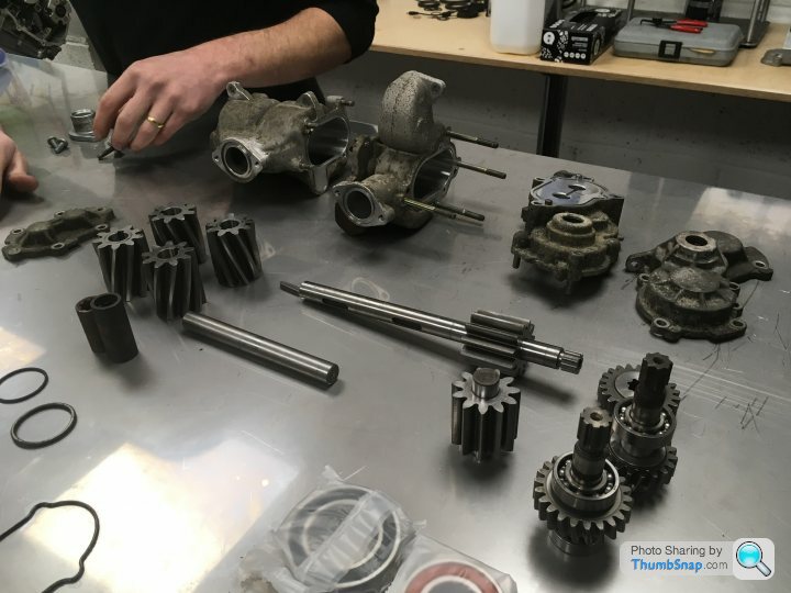
But first, I need to take you back a bit. And step somewhat off topic. The title of this thread is “Engine Rebuild”. So let’s look at a gearbox rebuild instead. Don’t worry, we won’t dwell on it too long; they mystify me too!
When I bought the car (some 65,000 miles ago) second gear was a little bolshy. And it hasn’t improved with age. But shifting around second wasn’t a problem, and once the ‘box was warm you could wrestler it into second if you really wanted to. But it wasn’t a pleasant operation. Ricky has at least as many Gallardo/Gen1 R8 gearboxes knocking about as he does engines (well, they DO tend to come in pairs!) so it made sense to have him open mine up and inspect it.
And yet again, he expressed genuine surprise at how little wear was evident, given the mileage. However, there WAS wear visible on the teeth of both the second gear gear-wheel and the engagement teeth within the locking collar of the second gear synchro set.
Sorry, no photos, largely because it looks like such light wear that I didn’t bother! I’ve only just started to wear reading glasses, and my near-vision is still pretty good without them, yet I had to look really carefully to see the rounding of the engagement faces of the gear teeth. But Ricky assures me that it’s this almost insignificant wear that was the culprit. As ever, prices are silly (but actually comparable to Audi’s prices for the Gen 1 R8, who’s Graziano-supplied gearbox is almost identical). Writing this at home, I’ve just looked at the Eurospares website for the prices, but I’m fairly sure that they’re quite wrong. I’ll edit this post with the actual prices once I’ve looked them out.

More surprising was the almost (but not quite) identical wear to the fourth gear gear-set. I’ve not noticed any difficulties with fourth gear, but Ricky assures me that I would have, probably sooner rather than later. So we elected to also replace both fourth and its corresponding synchro set (and they’re even pricier than second!). However, whilst the fourth gear gear-wheel is available, the synchro set isn’t! Despite having done 106,000 miles, the actual synchro rings were good; Ricky wouldn’t have bothered replacing them alone. But the engagement teeth within the locking collar were worn, and reinstalling it would result in premature wear of the brand new fourth gear. Luckily, Ricky dismantled a couple of his spare ‘boxes and the second one yielded a good-as-new fourth gear locking collar. One of the very many advantages of having your engine rebuilt by someone who really knows his stuff!
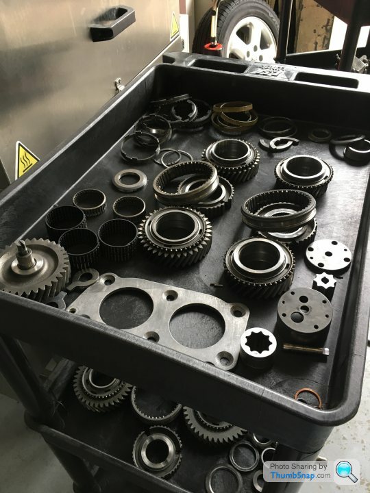
Several runs through the parts washer later and the ‘box was reassembled with new bearings throughout. Some of the gear wheels require heating to expand them before they are dropped onto the shaft. Amusingly, Ricky uses a (very) small domestic countertop oven/grill.

Reinstalled on the car, it was pretty much ready to start........
But first, I need to take you back a bit. And step somewhat off topic. The title of this thread is “Engine Rebuild”. So let’s look at a gearbox rebuild instead. Don’t worry, we won’t dwell on it too long; they mystify me too!
When I bought the car (some 65,000 miles ago) second gear was a little bolshy. And it hasn’t improved with age. But shifting around second wasn’t a problem, and once the ‘box was warm you could wrestler it into second if you really wanted to. But it wasn’t a pleasant operation. Ricky has at least as many Gallardo/Gen1 R8 gearboxes knocking about as he does engines (well, they DO tend to come in pairs!) so it made sense to have him open mine up and inspect it.
And yet again, he expressed genuine surprise at how little wear was evident, given the mileage. However, there WAS wear visible on the teeth of both the second gear gear-wheel and the engagement teeth within the locking collar of the second gear synchro set.
Sorry, no photos, largely because it looks like such light wear that I didn’t bother! I’ve only just started to wear reading glasses, and my near-vision is still pretty good without them, yet I had to look really carefully to see the rounding of the engagement faces of the gear teeth. But Ricky assures me that it’s this almost insignificant wear that was the culprit. As ever, prices are silly (but actually comparable to Audi’s prices for the Gen 1 R8, who’s Graziano-supplied gearbox is almost identical). Writing this at home, I’ve just looked at the Eurospares website for the prices, but I’m fairly sure that they’re quite wrong. I’ll edit this post with the actual prices once I’ve looked them out.
More surprising was the almost (but not quite) identical wear to the fourth gear gear-set. I’ve not noticed any difficulties with fourth gear, but Ricky assures me that I would have, probably sooner rather than later. So we elected to also replace both fourth and its corresponding synchro set (and they’re even pricier than second!). However, whilst the fourth gear gear-wheel is available, the synchro set isn’t! Despite having done 106,000 miles, the actual synchro rings were good; Ricky wouldn’t have bothered replacing them alone. But the engagement teeth within the locking collar were worn, and reinstalling it would result in premature wear of the brand new fourth gear. Luckily, Ricky dismantled a couple of his spare ‘boxes and the second one yielded a good-as-new fourth gear locking collar. One of the very many advantages of having your engine rebuilt by someone who really knows his stuff!
Several runs through the parts washer later and the ‘box was reassembled with new bearings throughout. Some of the gear wheels require heating to expand them before they are dropped onto the shaft. Amusingly, Ricky uses a (very) small domestic countertop oven/grill.
Reinstalled on the car, it was pretty much ready to start........
Gassing Station | Supercar General | Top of Page | What's New | My Stuff