3/5/7 angle valve jobs?
Discussion


spend said:
Only the one set of inlets & headers was what struck me as odd, but I only gave it a quick scan through.
The test was to see which heads worked best though. Introducing more variables would skew it even further.The test did seem to be geared towards a higher rpm setup, with relatively poor performance at the bottom end.
But that's just what the test was. Also they appeared to say they were just targeting a fixed AFR rather than tuning for best power/torque.
No doubt Dave has spotted something the rest of us have no clue about lol
Well this is all a bit disappointing. I hoped at least someone would be able to have a crack at analysing the figures. Two things should leap off the page at you in that test.
1) The modified heads have a fair spread of flow. 343 cfm at best to 313 at worst at the 600 thou valve lift the cam produced. That's nearly 10%, or 60 bhp on that engine, but the power figures barely alter. Apart from two heads they all cluster between 616 and 622 bhp which isn't even a 1% spread. If the engine was really seeing the flow differences in the heads the power spread would be much wider.
2) In the same vein the best modified head flows nearly 45% more than stock. Even the worst flows 32% better yet the average gain is only 70 bhp over the stock head's 550, under 13% gain. Again, if the engine was really seeing the flow figures of the modified heads they should all be producing over 700 bhp.
The conclusion is clear. The engine isn't seeing the real flow of the heads and the reason why should be even more obvious. The single butterfly plenum inlet manifold is strangling all of them down the the same flow number.
Looking up the manufacturer's website that manifold is designed for stock engines and to add a claimed 25 bhp over the stock induction system which I have no reason to doubt it does. Clearly however it can't fit both stock inlet ports and 20% bigger modified ones at the same time. Sure it could be ported out for the big heads and in fact is designed to come apart for this to be done but it never was. Even so it is doubtful it could cope with an extra 45% flow over stock. Only one butterfly per cylinder TBs or a plenum system with much bigger ports could do that.
So no matter which modified head was being tested they were all being limited to the flow the manifold could support and using one of my software programmes I can even calculate that number. To gain the 13% average extra power all the stock heads are showing the peak flow number through the manifold can only have been about 260 cfm. That's plenty for the stock 238 cfm head but for heads flowing between 313 and 343 cfm it's utterly pointless.
In fact this isn't a test of 10 modified heads at all. It's a test of one inlet manifold repeated 10 times and no sh*t sherlock it produced about 620 bhp every damn time. By 400 thou lift the modified heads were already exceeding the flow the manifold could supply and from then on to 600 thou plus they all flowed exactly the same. The only thing the heads could do is present higher or lower gas speeds to the cylinder depending on their port design which is why one stood out and two really sucked.
What a complete frigging waste of time and effort. Even worse I note from the links on the page that the idiot who did this repeated the exercise with other LS heads using a common, and similarly restrictive, manifold and got exactly the same results. They all showed the same bhp number. He even commented on it but apparently hasn't the intelligence to work out why or how pointless his tests are.
A chain is only as strong as its weakest link. Engines are all about combinations and a bottleneck in one component means every other one can't perform as it should. With an optimum inlet manifold the best of those modified heads should have showed nearly 730 bhp. Over 100 bhp was being sacrificed due to sheer stupidity and any differences the heads ought to have produced was being masked away to nothing.
I'm sure the manufacturers of the worst heads supplied to this magazine were highly relieved their products hadn't been shown up as being not very good but the manufacturers of the best heads must have been spitting feathers. All that careful flowbench and CNC work nullified by the tw*tmeister who hobbled their products down to a common level with a restrictive road spec inlet system.
So why was that so difficult for anyone to work out for themselves given I'm betting it now looks obvious with hindsight?
Edited by Pumaracing on Saturday 31st December 13:52
Pumaracing said:
So why was that so difficult for anyone to work out for themselves given I'm betting it now looks obvious with hindsight?
Because you have the experience of many years of dyno testing, flowbench testing etc etc.Edited by Pumaracing on Saturday 31st December 13:52
We do not.
The test is a valid test for upgrades many n/a runners will consider. The FAST intake is a relatively affordable simply bolt on intake.
SO in that respect, yes it may be holding back performance, but for a back to back test with a combination many people might be using, then then results are valid for them.
Very very few people in the US run ITB's on their cars. So what's the point in testing them like that ?
I'd assume that if the head suppliers knew the setup of the test, and werent happy, they would just not have bothered to volunteer heads for testing ?
I guess next question is, what sort of single throttle intake would have been a better option for the test ?
The FAST is pretty much deemed one of the better options. Many cars these engines are in, have bonnet clearance issues with other styles.
Pumaracing said:
So why was that so difficult for anyone to work out for themselves given I'm betting it now looks obvious with hindsight?
It is obvious, but I think you believe that more people looked at this than actually did.It does prove how easy it is to extract money off punters and more importantly, make profit. My bet is the best head has the most R&D and the smallest profit, the cack head, little R&D and big profit and to the punter there is little difference. A cynic could suggest that the manufactures of cack know it is cack, but the most profitable cack!
stevieturbo said:
I guess next question is, what sort of single throttle intake would have been a better option for the test ?
The FAST is pretty much deemed one of the better options. Many cars these engines are in, have bonnet clearance issues with other styles.
The answer has already been given. Only an induction system which doesn't limit the flow through the heads is a suitable choice to actually test the difference between heads. Anything else just tests the induction system and the difference between the heads disappears. What that ideal induction system would be for an LS engine I have no idea because before this thread started I didn't even know what an LS engine was. I had to Google it to find out and ended up at Wikipedia for whatever that's worth.The FAST is pretty much deemed one of the better options. Many cars these engines are in, have bonnet clearance issues with other styles.
I'm somewhat (a little) familiar with the original 350 Chevy engine and even did a pair of those heads once but I didn't know the engine had been redesigned nor do I have any clue about what tuning parts are available for it. I've had to work all this out from first principles with no knowledge of the engine to analyse the data in the magazine test.
If the FAST manifold can be ported out to match the flow of the best heads under test then fine. That would do the job. If not then a better induction system needs to be used.
If it shows anything this test shows just how much power can be lost by not getting the combination right. I'd like to think that even though I've never seen one of these engines I could build one of well over 700 bhp from the same parts, correctly modified, that only produced 620 bhp in the article.
If you understand how engines work in intimate detail it doesn't matter which one you tune. You can calculate the optimum way to go from first principles and prior knowledge of the specifics of that particular engine is unnecessary. That's why though even though so many of my jobs are one-offs I've never seen before they still win whatever they're competing in because the rules of tuning for bhp stay the same whatever the engine design is.
DV goes on at length about the importance of the "combination" in his books and I heartily endorse that but learning by rote a combination that works for one engine doesn't help you in the slightest with another different engine if you never understood the rules that made the first combination optimal.
It's a bit like the old adage "give a man a fish and you feed him for a day. Teach him how to fish and he'll bore the arse off everyone he knows with fishing stories for the rest of his life" or however it goes.
Just telling someone what combination to use on a particular engine is no better than giving him a fish. Teaching him why the combination works is like teaching him how to fish. He can feed himself for ever from then on.
However learning how and why engines work is hard work. Anyone who just wants the answers handed out on a plate and has no desire to think for themselves will never understand the rules.
For those out there who are prepared to do that hard work and think in great detail I'm happy to teach them. For those who aren't I'm wasting my time.
But again, it all boils down to what is available, at what cost and what fitment.
The "best" intake probably wont fit many cars. The "best" intake will likely cost a fortune.
Although it could beg the question would the "best" intake and some budget heads actually offer a better overall package than the most expensive heads and a more conventional intake..
Some Engine masters articles seem to use intakes like this.
http://www.popularhotrodding.com/tech/1112phr_raci...
Obviously highly impractical for most cars.
Then there are "sheet metal" intakes like those, although more commonly used with boost. Beautifully made, and I'd love to own one for that alone. But better performer than the plastic ones or cheaper carb style ? Who knows. I doubt they are worth the extra ( with boost anyway )


But going back to the original query. Brummie does use ITB's so would it be as simple as the best flowing heads with the smallest ports be the best for his setup ? Given his intake should pose little restriction ?
The "best" intake probably wont fit many cars. The "best" intake will likely cost a fortune.
Although it could beg the question would the "best" intake and some budget heads actually offer a better overall package than the most expensive heads and a more conventional intake..
Some Engine masters articles seem to use intakes like this.
http://www.popularhotrodding.com/tech/1112phr_raci...
Obviously highly impractical for most cars.
Then there are "sheet metal" intakes like those, although more commonly used with boost. Beautifully made, and I'd love to own one for that alone. But better performer than the plastic ones or cheaper carb style ? Who knows. I doubt they are worth the extra ( with boost anyway )
But going back to the original query. Brummie does use ITB's so would it be as simple as the best flowing heads with the smallest ports be the best for his setup ? Given his intake should pose little restriction ?
Although a little more googling. Seems there are some ITB that dont cost the earth, even if they have short runners ?
http://www.extrudabody.com/servlet/the-170/Manifol...
Except that's only the manifold price....typical lol
http://www.extrudabody.com/servlet/the-170/Manifol...
Except that's only the manifold price....typical lol
Pumaracing said:
This might indicate that the top cut on an inlet seat needs to be closer to the valve seat angle than previously thought. Perhaps 38 degrees for a 45 degree seat rather than a 30 degree topcut.
A very astute conclusion Mr. Baker - a lot of the NASCAR Cup Car and drag race ProStock heads are using a 38 degree top cut and a chamber wall at that angle.DV
Max_Torque said:
stevieturbo said:
Max_Torque said:
I bet the "charge robbing" is horrendous on that^^^^ ally manifold !
I dont think anyone uses them in n/a form, nearly always boosted.A supercharged V8 engine I was involved in the development of - in early form had a Volumetric efficiency of 110% on one cylinder and 140% on the best cylinder!!

stevieturbo said:
Although a little more googling. Seems there are some ITB that dont cost the earth, even if they have short runners ?
http://www.extrudabody.com/servlet/the-170/Manifol...
Except that's only the manifold price....typical lol
These are mine on 55mm chokes, i am under the impression i need to keep the taper going to the valve to keep airflow speed increasing...but i'm probably wrong!http://www.extrudabody.com/servlet/the-170/Manifol...
Except that's only the manifold price....typical lol
My valves are 51mm (2.02").
Edited by Brummmie on Tuesday 3rd January 22:43
David Vizard said:
I would be very interested in just how you were measuring this??
David Vizard
Inferred from the engine dyno:David Vizard
cylinder specific in the manifold branch 100 mm after the exhuast port using wide band oxygen sensors and emissions probes for spindt calculations for AFR ( spindt method using H and C in the exhaust is typically more trustworthy for AFR at rich ratios)and using a calibrated fuel injector (all fuel injectors were calibrated in the laboratory before being fitted to the engine) per cylinder to get fuel flow. Overall Fuel flow was measured using an AVL coriolis fuel flow measurement device (both in the laboratory and for the OVERALL engine average). From AFR and fuel flow we inferred air flow per cylinder. Not as accurate as using some form of direct measurement such as a hot wire annamometer or viscous flow but other measures helped: Each cylinder was instrumented up using water cooled Kistler pressure transducers. This low cylinder pressure (nominal average for all cylinders was about 80 bar) was lower and corresponded to the lower inferred air flow. In addition a GT Power/Ricardo WAVE model (1 D cycle simulation) was constructed of the engine and several weeks spent correlating to the baseline dyno data to characterise the engine and dynamic flows and pressures within the engine. This simulation corroborated our dyno findings remarkably accurately. Infact cycle sim and 3 D CFD were used as design tools to try to reach better design compromises during the engine development programme. The most fun you can have with your lab coat on

Edited by Marquis Rex on Wednesday 4th January 06:21
David Vizard said:
My new cylinder head book really delves into the myths, misconceptions, underestimations and the realities of port velocity. It actually has diagrams in it that explain why even those who tell you it's important are doing little other than paying lip service to this element of cylinder head modifying. There are also dyno tests to show what happens to the type of engines you and I run (as apposed to F1) when port velocity is changed.
Book will be out late feb and in books stores hopefully by end of March.
And Dave B - please don't spill the beans on this one!!
DV
Hi David, let me add my welcome to you joining the site. As has already been said, this site mainly acts as a place for the ignorant lokking for advice from the well knowledged (often receiving advice from the equally ignorant) but often a useful Q and A session becomes a great read whether one has the sme issue or not...a little rambling nd off topic sometimes but still useful. Should you irk out a deal for a series of articles, I think it would be great to have a ballance between explination of cutting edge technology and actual real world DIYable tips. Book will be out late feb and in books stores hopefully by end of March.
And Dave B - please don't spill the beans on this one!!
DV
I've read some great inadvertant articles from Mr Puma over the years and we've heard some great works of wisdom on how *not* to port a head and what the porter should be looking for, but articles on how one could succesfully port a head at home (f it were possible to construct a home made flow bench or example) would be great.
I think there a a few experts on here (certainly one more now), a few keen amatures and a lot of interested but don't have the knowledge to offer advice types.
I'd love to know how to measure the flow on my heads and any quick wins to improve them...oh and yes...what NOT to do too....
Will be looking out or the book in due course...
Cheers, Neil
Max_Torque said:
I bet the "charge robbing" is horrendous on that^^^^ ally manifold !
The design of single butterfly plenum manifolds is not one of my strong areas so I'd appreciate more explanation of your thoughts above and what would ideally be done to optimise the design to which I suspect you'll answer "much more plenum volume".stevieturbo said:
Although a little more googling. Seems there are some ITB that dont cost the earth, even if they have short runners ?
http://www.extrudabody.com/servlet/the-170/Manifol...
Except that's only the manifold price....typical lol
I really don't like the design of those. The vertical butterfly housings turning abruptly into the ports over a very short distance is not ideal for flow. I flow tested a 4 cylinder DCOE manifold for a 16v Golf once that had a similar design and involved a 45 degree bend within under a couple of inches length and it flowed worse than the stock single butterfly plenum.http://www.extrudabody.com/servlet/the-170/Manifol...
Except that's only the manifold price....typical lol
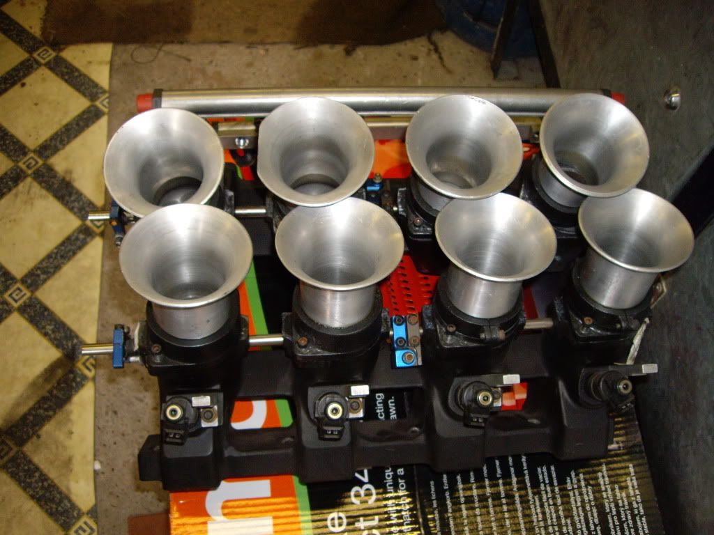
Brummmie said:
These are mine on 55mm chokes, i am under the impression i need to keep the taper going to the valve to keep airflow speed increasing...but i'm probably wrong!
My valves are 51mm (2.02").
The design of those looks pretty decent. You're certainly not short of butterfly size! 55 mm ones would support nearly 100 bhp per cylinder but there's not that much downside to oversizing on FI systems as compared to carb chokes. The overlap of the trumpet edges might be hurting things a bit.My valves are 51mm (2.02").
A flowtest of the manifold mounted on the head as compared to the bare head would tell you a lot more and indicate if there is scope for modification.
The blue anodized throttle linkages look rather familiar. Those are what we made when I did my own TBs many years ago. I wonder who you got those from?
Gassing Station | Engines & Drivetrain | Top of Page | What's New | My Stuff