Ideal Camshaft Lobe Centreline Angle
Discussion


Pumaracing said:
DV and myself are using the term LCA to refer to what you are calling LSA i.e the angle between the inlet lobe peak position and the exhaust lobe peak position. The actual cam timing in terms of advance or retard is given by the inlet full lift position which you are referring to as the LCA.
Maybe both myself and DV should start using the term LSA to refer to what we have previously called LCA. If he will I will.
Mmm.. the confusion has arisen because the graph says 'Lobe Centreline Angle' as does the topic title which is more than a bit ambiguous as I would take that to mean the centre of the lobe, I.E. the full lift point.Maybe both myself and DV should start using the term LSA to refer to what we have previously called LCA. If he will I will.
Essentially if the cam is symetrically timed, LCA and LSA are the same thing or at least have the same value, except one is measured in crank degrees from TDC (the centre of LSA) and the other in cam degrees between the lobe centres.
It also answers the question about whether the tests were undertaken with a different shaft each time
 .
.It occurs to me that rod angle will have an affect on ideal LSA/LCA as it materially affects the differential rates of piston acceleration and therefore the point at which there is maximum draw on the cylinder per crank degree.
Dave
Edited by DVandrews on Thursday 26th January 10:32
Workshop said:
Thanks David, it was really just a stab in the dark while I was having a coffee before I went to work. Really there was no sense trying to adapt CFM to the formula because I have no idea why it is multiplied by 16/14 and then 132 subtracted by it in the first place.
I afraid I assumed everyone would know how to generate the equation of a straight line graph but I suppose I do take maths for granted somewhat. It should be apparent that the LCA rises by 16 degrees as the CID/inch falls by 14 (from 28 to 14). The slope of the line is therefore -16/14 x CID/inch.It should also be clear that the line intersects the X axis at an LCA of 132. The LCA has risen from 100 to 116 as the CID/inch falls from 28 to 14 so a drop in CID/inch of another 14 to zero would add 16 more to the LCA. 116 + 16 = 132.
So the equation of the line is 132 - (16/14 x CID/inch).
So when CID/inch is zero then LCA must be 132 which it is. When CID/inch is 28 then LCA = 132 - (28 x 16/14) = 100 which again it is and similarly for any value in between or even either side of those.
However given we've established that LCA is not dependent on CID/inch in the first place it's sort of academic.
 t now..
I think it is important to clear some things up at this stage
The following applies to 2v single cam engines
The LSA cannot be changed, the LCA can be changed by advancing or retarding the cam, but he LSA will remain the same
LSA cannot be measured directly off the camshaft it has to be measured installed in an engine with lash, with a dial gauge on top of the spring retainer and a large degree wheel (10”+ ) bolted to the flywheel or front pulley
LCA is simply a description of cam timing position in relation to the crankshaft both for inlet and exhaust, this is usually quoted as the full lift point but much more accurately would be to measure the timing events @.010" and .050" lift and determine what the LCA is for both inlet and exhaust and the LSA at these lift points with lash
Some important question for DV:
With all the graphs you have made were you using different LSA's with each of the cams and the same profiles with the same intake LCA, ending up with the same inlet timing but with a change in LCA for the exhaust lobe?
Or were the cams with different LSA's timed in to give the best power curve with varying inlet closing points and the same static compression ratio?
Getting back to selecting an ideal Lobe Separation Angle to get the best power out of a particular engine
Some of the main factors I can think of that influence the ideal LSA to use for a given engine:
1. Engine application, how wide the power band needs to be and at what rpm’s you want best power/torque, (determined by Duration and LSA)
2. The maximum Static Compression Ratio being used to suit the fuel you are using (slightly wider LSA for increased compression)
3. Suitable inlet closing point to suit the SCR
4. Using enough lobe Duration to make the power curve shape you are after judging by the head flow graph
5. Using enough Overlap Area to make the peak power you are aiming for, too little will reduce cylinder filling by not properly getting rid of all the exhaust gasses in the chambers and filling them with fresh charge/using the exhaust overlap to get the inlet charge to move rapidly with the piston still parked at TDC (then piston motion taking over from there)
Too much overlap will reduce idle and low rpm quality, the engine will also come on cam more abruptly due to flow reversals at low rpm
6. Valve size, this has a direct effect on low lift flow which increases the overlap flow with a given camshaft as compared to the same engine with smaller valves
7. Cylinder capacity vs port flow, DV suggests increased cylinder cc needs a tighter LSA and less cc or greater valve size needs a wider LSA
8. Engines with shared ports for each cylinder will need to use a tighter LSA
As said LSA’s around 104 to 111* appear to work best for most engines 2v & 4v with 107* being a good starting point
I would suggest that very tight LSA’s produce an engine that has poor low rpm response, comes into the power band abruptly, great midrange to upper rpm power, wider LSA’s give better low rpm response, reduced midrange, sometimes higher peak power, power tends to drop off slower after peak hp
If someone does not agree with any of the above please say so, state why you think otherwise and offer your own theories in detail, try and keep the comments respectful, there is no need to tear someone else’s theories apart. No one has ALL the answers
Then we can all make our own minds up as to what LSA “could” work best for a given engine
Regards
Jason
Rwdfords said:
6. Valve size, this has a direct effect on low lift flow which increases the overlap flow with a given camshaft as compared to the same engine with smaller valves
You have to be extraordinarily careful when making assumptions about how one thing affects another thing that some of the factors haven't been missed.If you increase valve size then you increase overlap flow but you also increase cylinder filling, which of course then requires more overlap flow to evacuate it and the factors cancel out.
Something I'll bet very few have ever realised is that you automatically change the ratio of low lift to high lift flow simply by changing valve size.
A 25mm diameter valve has an area of 25 x 25 x pi / 4 = 491 mm^2. The ratio of area to diameter is 19.6
Double the valve size to 50mm. The area is now 1963 mm^2 and the ratio of area to diameter is 39.3
So a small valve has more diameter (or circumference) for a given head area than a large one and with a cam of the same lift will have a different ratio of low lift to high lift flow. Swap one large valve for two small ones of the same total area and the effect multiplies. However if more low lift flow required a change in the LSA then small 4v engines would have radically different numbers than large 2v ones yet they don't. It all cancels out in the wash.
What the flow per cc does tell you is how much cam duration you need for a given state of tune.
A big factor that affects optimum LSA is the rod / stroke ratio and that is what I was referring to when I said the Pinto was geometrically similar to the 350 Chevy. That's the subject I'll get into in detail if I get time.
Edited by Pumaracing on Friday 27th January 00:15
Pumaracing said:
A big factor that affects optimum LSA is the rod / stroke ratio and that is what I was referring to when I said the Pinto was geometrically similar to the 350 Chevy. That's the subject I'll get into in detail if I get time.
Pretty much this then..? DVandrews said:
It occurs to me that rod angle will have an affect on ideal LSA/LCA as it materially affects the differential rates of piston acceleration and therefore the point at which there is maximum draw on the cylinder per crank degree.
The higher the rod angle / lower the rod ratio, the greater the piston acceleration during the first half of the induction stroke, the swept volume at 90ATDC will be far greater than the swept volume of remaining 90 degrees of crank movement since the piston will be much further than 50% of the way down the bore. On one particular engine I know well, the rod ratio is around 1.50 and the percentage of swept volume at 90ATDC is approaching 60%, on it's shorter stroked brother, the rod angle is a much more favourable 1.77 and the swept volume percentage is more like 56%.Intuitively it would make sense to have the MOP(LCA) earlier in the induction stroke on an engine with a poor rod angle/rod ratio than one with a more favourable (lower) rod angle and (higher) rod ratio. With higher rod ratios/lower rod angles, the difference between the first and last halves of the stroke in terms of swept volume will tend further toward equality.With an infinitely long rod the piston would be exactly halfway down the bore at 90ATDC.
All other aspects beign equal, moving the LSA closer together on engines with poor rod ratios would make sense.
Rwdfords said:
With all the graphs you have made were you using different LSA's with each of the cams and the same profiles with the same intake LCA, ending up with the same inlet timing but with a change in LCA for the exhaust lobe?
Or were the cams with different LSA's timed in to give the best power curve with varying inlet closing points and the same static compression ratio?
Indeedy, that's what I was driving at earlier in the thread.Or were the cams with different LSA's timed in to give the best power curve with varying inlet closing points and the same static compression ratio?
DVAndrews said:
Interesting thread.. looking at the graph, can I assume that the curves are derived from a single camshaft which has the LCA moved around rather than a number of cams with the LCA and lobe separation tailored to suit. If that is the case, what was the lobe separation angle?, where is the notional 'nuetral' position of the cam WRT LCA?. The reason I ask is that moving the LCA on the inlet will have an affect on the exhaust LCA as well. It's one thing to determine the ideal LCA and cut a cam with correct LCA and lobe separation, but another altogether to simply swing an existing cam through an LCA arc as this will move both lobe centres. On twin cam engines there is scope for moving each cam independently to arrive at the optimum for each camshaft. On a single cam engine this needs to be determined before the cam is cut.
DaveEdited by DVandrews on Friday 27th January 11:46
I think most people who haven't studied engines in depth could be forgiven for assuming that the motion of the piston up and down the bore is somewhat symmetrical. That it sets off from TDC at a certain acceleration, reaches peak velocity half way down the bore and then slows down in a similar fashion to reach BDC.
Well nothing could be further from the truth. In a real engine due to the complex nature of the rod / crank geometry the piston accelerates away from TDC nearly twice as fast as it accelerates away from BDC. It reaches peak velocity in as little as 70 degrees from TDC and then spends the next 110 degrees slowing back down. This behaviour changes as the length of the conrod varies proportionate to the crank stroke. The longer the rod / stroke ratio the slower the piston accelerates away from TDC and the faster it approachs BDC. Only with an infinitely long conrod would the motion finally become symmetrical with peak velocity half way down the bore and the same acceleration at TDC and BDC.
The graph below shows how the acceleration changes as the rod/stroke ratio changes.
With ratios below about 1.6 the behaviour near BDC is quite bizarre and the acceleration curve is W shaped with two minima either side of BDC. Anyway that doesn't need to concern us for now.
What does need to be understood is that as the rod / stroke ratio increases the piston will always be slightly higher up the bore at any given crank angle away from TDC than it would be with a lower ratio.
Real world rod / stroke ratios range from a low of about 1.4 to a high of about 2.4 although there is no upper limit if the designer so chooses. Most production car engines have ratios in the range 1.55 to 2.0. The longest ratio in common use I know of is the old 2.9 litre straight 6 Jaguar XJ6 engine which has a ratio of 2.34. The 2.0 Pinto and 350 Chevy are both around 1.65, the 1275 A series is 1.8, the MGB even higher at 1.86 and very high rpm engines like the CBR600RR I mentioned previously tend to have ratios over 2 to minimise thrust forces against the bore and piston accelerations at TDC. The Honda actually has a ratio of 2.16.
The magnitude of the change in piston position when the rod ratio changes from the very low (1.4) to the comparitively high (2.20) is about 4 degrees of crankshaft movement.
So what effect does all this have on cam timing? Let's imagine we have an engine with a very low rod ratio, say 1.45, and we have optimised the cam events. Now we change the engine to have a very high rod ratio of say 2.20.
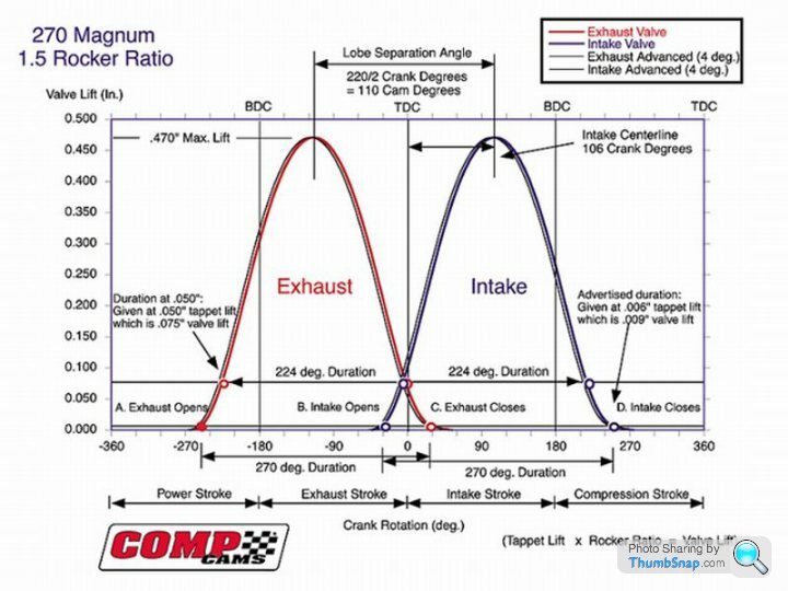
Assume our cam is the old faithful fast road profile from the 1950s that was always known as the 30/60 60/30 profile. This means it has a duration of 270 degrees, is timed straight up i.e. no advance or retard and has an LSA of 105 degrees.
Starting with the exhaust valve opening event. This occurs at 60 degrees BBDC which on the short rod engine represented a specific piston position a certain distance from BDC. However on the long rod engine the piston will be higher up the bore at the same crank angle. It will take another 4 crank degrees before it reaches the same distance away from BDC. So to compensate we need to open the exhaust valve 4 degrees LATER, at 56 degrees BBDC.
The inlet valve close shows a similar story. The piston position at 60 degrees ABDC will now occur at 56 degrees ABDC on the long rod engine so we need to close the inlet valve 4 degrees EARLIER.
We find the same story at the inlet valve opening and exhaust closing points. The inlet needs to open earlier and the exhaust close later.
So our 270 degree cam now becomes a 34/56 56/34 profile which means the LSA has narrowed to 101 degrees.
So there's our golden rule with rod / stroke ratios. The higher the ratio the smaller the LSA needs to be. As an approximation every 0.15 points change in ratio needs about 1 degree change in LSA. It's not an absolute and the effect varies somewhat with cam duration but that'll get you in the ballpark.
So taking our starting point as the Pinto engine with a 1.65 ratio and a theoretical 107 degree LSA then moving to the A series engine we'd theoretically need to narrow the LSA to 106 degrees. Moving further to the 2.16 ratio of the Honda CBR we'd need to knock another 2 degrees off to get to 104 degrees LSA. Now go back to my previous post and see what those engines actually had.
Now of course like anything engine related it's not quite as simple as that but that's enough complexity for now.
I suppose my closing views on LSA is it's not really such a big deal if you apply sensible rules. In fact I find that the cam offerings from most manufacturers do put you somewhere close to what you really need. For most people who don't have access to unlimited dyno time you'll never know how far out you were and comparing to other people's engines will simply lose any observable cam effects in the variations in head flow, induction and exhaust system differences etc.
I'm not saying the cam companies know everything, or even very much at all about how engines work, but over the decades what works and what doesn't has filtered down until you see a general consensus in most cam grinds. Stock road profiles have wider LSAs, say 110-112 degrees, to give good idle and low rpm manners. By the time durations have increased to fast road / rally profiles the LSA narrows down a bit by 3 degrees or so. Full race narrows even further usually. It might not be perfect but if your engine has a good head, the right CR and a decent quality build I've never found the cam to be the determinant of whether it'll win or not. I usually plump for a bit less duration than most people think they need and build an engine with stonking torque and easy driveability. If the driver can pedal that properly and the engine has one of my heads on it he'll win more often than not.
Well nothing could be further from the truth. In a real engine due to the complex nature of the rod / crank geometry the piston accelerates away from TDC nearly twice as fast as it accelerates away from BDC. It reaches peak velocity in as little as 70 degrees from TDC and then spends the next 110 degrees slowing back down. This behaviour changes as the length of the conrod varies proportionate to the crank stroke. The longer the rod / stroke ratio the slower the piston accelerates away from TDC and the faster it approachs BDC. Only with an infinitely long conrod would the motion finally become symmetrical with peak velocity half way down the bore and the same acceleration at TDC and BDC.
The graph below shows how the acceleration changes as the rod/stroke ratio changes.
With ratios below about 1.6 the behaviour near BDC is quite bizarre and the acceleration curve is W shaped with two minima either side of BDC. Anyway that doesn't need to concern us for now.
What does need to be understood is that as the rod / stroke ratio increases the piston will always be slightly higher up the bore at any given crank angle away from TDC than it would be with a lower ratio.
Real world rod / stroke ratios range from a low of about 1.4 to a high of about 2.4 although there is no upper limit if the designer so chooses. Most production car engines have ratios in the range 1.55 to 2.0. The longest ratio in common use I know of is the old 2.9 litre straight 6 Jaguar XJ6 engine which has a ratio of 2.34. The 2.0 Pinto and 350 Chevy are both around 1.65, the 1275 A series is 1.8, the MGB even higher at 1.86 and very high rpm engines like the CBR600RR I mentioned previously tend to have ratios over 2 to minimise thrust forces against the bore and piston accelerations at TDC. The Honda actually has a ratio of 2.16.
The magnitude of the change in piston position when the rod ratio changes from the very low (1.4) to the comparitively high (2.20) is about 4 degrees of crankshaft movement.
So what effect does all this have on cam timing? Let's imagine we have an engine with a very low rod ratio, say 1.45, and we have optimised the cam events. Now we change the engine to have a very high rod ratio of say 2.20.
Assume our cam is the old faithful fast road profile from the 1950s that was always known as the 30/60 60/30 profile. This means it has a duration of 270 degrees, is timed straight up i.e. no advance or retard and has an LSA of 105 degrees.
Starting with the exhaust valve opening event. This occurs at 60 degrees BBDC which on the short rod engine represented a specific piston position a certain distance from BDC. However on the long rod engine the piston will be higher up the bore at the same crank angle. It will take another 4 crank degrees before it reaches the same distance away from BDC. So to compensate we need to open the exhaust valve 4 degrees LATER, at 56 degrees BBDC.
The inlet valve close shows a similar story. The piston position at 60 degrees ABDC will now occur at 56 degrees ABDC on the long rod engine so we need to close the inlet valve 4 degrees EARLIER.
We find the same story at the inlet valve opening and exhaust closing points. The inlet needs to open earlier and the exhaust close later.
So our 270 degree cam now becomes a 34/56 56/34 profile which means the LSA has narrowed to 101 degrees.
So there's our golden rule with rod / stroke ratios. The higher the ratio the smaller the LSA needs to be. As an approximation every 0.15 points change in ratio needs about 1 degree change in LSA. It's not an absolute and the effect varies somewhat with cam duration but that'll get you in the ballpark.
So taking our starting point as the Pinto engine with a 1.65 ratio and a theoretical 107 degree LSA then moving to the A series engine we'd theoretically need to narrow the LSA to 106 degrees. Moving further to the 2.16 ratio of the Honda CBR we'd need to knock another 2 degrees off to get to 104 degrees LSA. Now go back to my previous post and see what those engines actually had.
Now of course like anything engine related it's not quite as simple as that but that's enough complexity for now.
I suppose my closing views on LSA is it's not really such a big deal if you apply sensible rules. In fact I find that the cam offerings from most manufacturers do put you somewhere close to what you really need. For most people who don't have access to unlimited dyno time you'll never know how far out you were and comparing to other people's engines will simply lose any observable cam effects in the variations in head flow, induction and exhaust system differences etc.
I'm not saying the cam companies know everything, or even very much at all about how engines work, but over the decades what works and what doesn't has filtered down until you see a general consensus in most cam grinds. Stock road profiles have wider LSAs, say 110-112 degrees, to give good idle and low rpm manners. By the time durations have increased to fast road / rally profiles the LSA narrows down a bit by 3 degrees or so. Full race narrows even further usually. It might not be perfect but if your engine has a good head, the right CR and a decent quality build I've never found the cam to be the determinant of whether it'll win or not. I usually plump for a bit less duration than most people think they need and build an engine with stonking torque and easy driveability. If the driver can pedal that properly and the engine has one of my heads on it he'll win more often than not.
You could look at it that way if you look at open/close events and piston position only, hoewever, coinciding maximum lift with maximum draw on the cylinder would suggest moving in the opposite direction.
In terms of simple airflow requirement, there is bias further towards the beginning of the stroke on a high rod angle engine since the first 90 degrees of crank rotation attempt to draw 60% of the cylinder charge, this would suggest that opening the valve earlier would be of benefit by biasing the lift curve in the same direction.
Dave
Edited by DVandrews on Friday 27th January 14:58
DVandrews said:
You could look at it that way if you look at open/close events and piston position only, hoewever, coinciding maximum lift with maximum draw on the cylinder would suggest moving in the opposite direction.
Then you'd first have to come up with a convincing argument why having maximum valve lift closer to peak piston speed makes any difference. In the average engine the piston reaches peak velocity at about 75 degrees ATDC. The inlet valve is not fully open until about 30 degrees later which is a long way apart. If matching those events was a big deal camshafts would be radically different.The piston generates a finite amount of depression as it sweeps from TDC to BDC. If the cylinder fills a bit worse at the start it will have a higher pressure differential over the inlet port later and flow more as the valve closes. If it fills well at the start it will flow less later. Swings and roundabouts tend to even all this out.
However at inlet valve close for example the valve wants to close at a certain cylinder pressure which balances the incoming charge momentum down the inlet port. Close too late and reverse flow will occur. That's determined by piston position which is in turn determined by rod / stroke ratio. Same applies to exhaust valve opening. You want to strike a balance between extracting energy from the burning charge and getting the exhaust gases out later. Piston position is key to all this.
At the end of the day you can posit any arguments you like but when Bill Jenkins went through all this on the dyno and race track in the 70s with the Chevy engine he found empirically that long rods wanted narrow LSAs and vice versa. I believe my argument explains this from simple first principles.
If you want to posit an argument that flies in the face of empirical testing it had better be a very good argument.
I have done some emprical testing of my own and it seems to contradict what you have posted.
However it isn't something that is easy to test.
My own experiences on identically specced engines that have gone from a high rod ratio(long rod) to low rod ratio (short rod) show that to achieve the largest area under the torque curve, the lobe separation angle has to go down by around 3 degrees. Admittedly the capacity and stroke have increased, but all other factors have remained the same. No doubt there are other factors to consider.
Of course there is a finite amount of draw on the cylinder, however the purpose of the cam is to make sure that there is an air supply while the piston is descending.
You wouldn't expect the valve events to exactly match the piston events as air takes time to accelerate, things dont happen instantaneously, if you move the inlet cam LCA around you can easily see the affect on torque, too far retarded and the torque will drop off rapidly in the mid range.
The thing about any theory is that it should fit the data and in fact predict it.
I'd agree that the rod angle has an affect on LCA, but having seen the opposite affect on a number of engines in controlled circumstances I am a little sceptical.
At this moment I am working on another engine where the rod ratio will be changing from 1.78 to 1.5 (a stroke increase) all other factors will remain the same. The cam timing was optimised on the dyno and gave the best curve at 106 ATDC, 108 BTDC. When the engine is converted I would normally advance the inlet cam by 2-3 degrees or so and retard the exhaust cam by a similar amount, this would bring the LSA in by around 2-3 degrees, normally this will give the best results.
I will ensure that when this engine is mapped I will first try widening the LSA to see what sort of result it gives.
Dave
Edited by DVandrews on Friday 27th January 21:07
DVandrews said:
At this moment I am working on another engine where the rod ratio will be changing from 1.78 to 1.5 (a stroke increase) all other factors will remain the same. The cam timing was optimised on the dyno and gave the best curve at 106 ATDC, 108 BTDC. When the engine is converted I would normally advance the inlet cam by 2-3 degrees or so and retard the exhaust cam by a similar amount, this would bring the LSA in by around 2-3 degrees, normally this will give the best results.
I will ensure that when this engine is mapped I will first try widening the LSA to see what sort of result it gives.
What you are doing here is not quite the same situation as Jenkins was facing though. If you increase capacity but leave the head and cam alone then the engine will not rev so high, the powerband will shrink and the cam is now effectively a milder one than it was on the smaller engine. Jenkins was trying to get the most power out of every engine in every situation.I will ensure that when this engine is mapped I will first try widening the LSA to see what sort of result it gives.
For example in 354 cubic inch drag engines he used 290 degrees of inlet duration, in the 330 that dropped to 286 degrees and in the 302 to 282 degrees. His findings on LSA were in terms of what worked best after he'd reoptimised the state of tune for the different capacity. The more flow per cc the less cam duration is needed.
In fact he preferred smaller capacity bottom ends for drag use because they revved higher and gave more power. Track engines would not sustain such high rpm for extended periods though so he made the bottom ends bigger to bring the rpm down and increase reliability.
So it's quite possible you won't find the same solution on LSA if you leave cam duration alone as if you changed duration at the same time as the capacity.
Edited by Pumaracing on Saturday 28th January 07:49
Rwdfords said:
That LSA chart is engine specific,
Having found "How to Build Horsepower" on Google books..http://books.google.co.uk/books?id=OAw1GDB0kN0C&am...
it would seem no it isn't. According to the text on the page above and below it's meant to be applicable to any parallel valve 2v engine or indeed supposedly any 4v one with a modified head with good valve seats. Not sure why the modified head is necessary.
So given we've established it only works for the Chevy size engines it was based around anyway for which it generally predicts LSAs between 105 and 110 degrees as any other engine would want and goes haywire for anything smaller like the A series or a bike engine I think that's the last nail in the coffin for CID/inch of valve diameter and back to the drawing board for Mr V.
BTW, for anyone who thinks I'm having a right old pop at the Viz with no prior warning I emailed him all this privately two years ago when he first drew my attention to the graph, the CID/inch theory and the supposed magic number of 128 for predicting cam LSA. I said it didn't work then and I stick to that now.
So we're left with some critical thinking to do. If LSA does not respond to valve size per cc i.e. therefore also flow per cc what else apart from rod / stroke ratio does it respond to if anything? Are the dyno tests that show it changing a bit as engine capacity changes for a given head just white noise? If flow doesn't matter than surely rocker ratio doesn't either because that just alters overlap flow. How about CR? Is that a real influence?
Thinking hats on people.
I have a few ideas but I think it's time for a detailed response by DV first.
stevesingo said:
Just in case it may help you theorise this engine:
Bore+95mm
Inlet cam 272, 11.5 lift timed peak lift at 106
Exhuast cam 248 105mm lift timed 106
Inlet valve 38.5mm, Exhaust 32mm
Inlet port flow 264cfm@ 0.400" lift @ 28"
Inlet port flow 268cfm@ 0.450" lift @ 28"
Not sure what you're asking me if anything. The head flow is pretty grim for those valve sizes. Clearly it's a stock head with a discharge coefficient of only 0.5. If that could be raised to 0.6 there'd be a bunch of power to come. Well, 20% obviously or at least something close to that and that's before sticking some decent cams in it which would add another 10% or more. I've never met a 4v head I couldn't get up to a Cd of 0.6 or thereabouts.Bore+95mm
Inlet cam 272, 11.5 lift timed peak lift at 106
Exhuast cam 248 105mm lift timed 106
Inlet valve 38.5mm, Exhaust 32mm
Inlet port flow 264cfm@ 0.400" lift @ 28"
Inlet port flow 268cfm@ 0.450" lift @ 28"
I'd be looking at about 70 to 75 bhp per cylinder in road tune for something like that and 90 in race trim.
Workshop said:
Are you basing the LSA of 107 for a 1.65 rod ratio starting point on the best LSA you have found for the Pinto engine ?
Yes. For high duration cams anyway. The Sig Erson 134 grind was a cracking cam for road vehicles with 500 thou lift from 276 degrees on a 110 LSA but it wore out like buggery. Piper and Kent used to do a copy, probably still do but smaller LSAs work better on longer duration cams.Edited by Pumaracing on Saturday 28th January 08:35
Gassing Station | Engines & Drivetrain | Top of Page | What's New | My Stuff