Ideal Camshaft Lobe Centreline Angle
Discussion


Your scales and theoretical choice of extreme rod lengths make the differences look far greater than any are likely to be encountered in real life. Unless you anotate them as such they may be rather misleading IMHO.
Probably of greater interest would be sensible examples of volume / degree, but from my trials of the maths in animations they are only marginal differences with rod lengths that you could really design pistons for.
Isn't the acceleration plot out of phase by 90degs BTW?
Probably of greater interest would be sensible examples of volume / degree, but from my trials of the maths in animations they are only marginal differences with rod lengths that you could really design pistons for.
Isn't the acceleration plot out of phase by 90degs BTW?
Mmm.. the most extreme example of rod length would be unworkable in a real engine as the rod angle would mbe cripplingly high. Most production engines vary between a rod ratio of 1.40 and 1.90. Even using these lower extremes there are some fundemental differences in piston position and piston speed/acceleration.
The difficutly in measuring the affect of a change in rod angle is in keeping the rest of the engine parameters exactly the same. In practice this would be almost impossible to do. The only time I have been in a position to get near was with a one-off conversion involving a new shorter stroke crank with larger bore (same capacity) with all other components the same. Even then the affect of the larger bore can skew the results.
Dave
jmm25577 said:
Guys been reading with with great interest and finding the input invaluable. David I carried your aseries boook everywhere in my Mini days, a legendary piece of literature! Currently rebuilding my ff2000 pinto and thinking of trying to change the standard LCA of 113 degrees, I figured this could be altered by playing around with valve seat height, valve legnths and rockers although min valve lengthhas to be 110.55mm. Obviously there will be a trade off with lift in one direction or LCA in the other. I thought 110 LCA and sacrifice some lift? Other alternative is go to 115 to get max lift with min legnth valves? Compression is 9.9-1. Jim
I would maximise the lift and not worry about the LSA if you are forced to use a stock cam. Re your email I'm moving house at the moment and won't be set up again for probably some months but I'll notify when I'm taking orders again on the site.spend said:
Your scales and theoretical choice of extreme rod lengths make the differences look far greater than any are likely to be encountered in real life. Unless you anotate them as such they may be rather misleading IMHO.
Probably of greater interest would be sensible examples of volume / degree, but from my trials of the maths in animations they are only marginal differences with rod lengths that you could really design pistons for.
Isn't the acceleration plot out of phase by 90degs BTW?
Probably of greater interest would be sensible examples of volume / degree, but from my trials of the maths in animations they are only marginal differences with rod lengths that you could really design pistons for.
Isn't the acceleration plot out of phase by 90degs BTW?
DVandrews said:
Mmm.. the most extreme example of rod length would be unworkable in a real engine as the rod angle would mbe cripplingly high. Most production engines vary between a rod ratio of 1.40 and 1.90. Even using these lower extremes there are some fundemental differences in piston position and piston speed/acceleration.
The difficutly in measuring the affect of a change in rod angle is in keeping the rest of the engine parameters exactly the same. In practice this would be almost impossible to do. The only time I have been in a position to get near was with a one-off conversion involving a new shorter stroke crank with larger bore (same capacity) with all other components the same. Even then the affect of the larger bore can skew the results.
Dave
First the acceleration graph is correctly alined.The difficutly in measuring the affect of a change in rod angle is in keeping the rest of the engine parameters exactly the same. In practice this would be almost impossible to do. The only time I have been in a position to get near was with a one-off conversion involving a new shorter stroke crank with larger bore (same capacity) with all other components the same. Even then the affect of the larger bore can skew the results.
Dave
These graphs all use the same 87 mm stroke but use a 121.8 mm rod (1.4:1) and a 165.3 mm rod (1.9:1).
Stan
[url][img]http://thumbsnap.com/sc/KPRVl8ov.gif[/img]|http://thumbsnap.com/KPRVl8ov[/url]

[url][img]http://thumbsnap.com/sc/pbMB9Seg.gif[/img]|http://thumbsnap.com/pbMB9Seg[/url]

[url][img]http://thumbsnap.com/sc/8cOvuxLE.gif[/img]|http://thumbsnap.com/8cOvuxLE[/url]

[url][img]http://thumbsnap.com/sc/YwXAB0Vn.gif[/img]|http://thumbsnap.com/YwXAB0Vn[/url]
Edited by Stan Weiss on Wednesday 1st February 18:22
Stan Weiss said:
First the acceleration graph is correctly alined.
These graphs all use the same 87 mm stroke but use a 121.8 mm rod (1.4:1) and a 165.3 mm rod (1.9:1).
Stan
(I snippied the graphs out - and my questions are by no means aimed directly at your graphs Stan).These graphs all use the same 87 mm stroke but use a 121.8 mm rod (1.4:1) and a 165.3 mm rod (1.9:1).
Stan
Just curious - which I think is a good thing. I want to walk through my thinking that hopefully will help others understand what they are looking at.
I'm assuming that the area of/under/over the curves (red and green in this case (lots of other colours in some of the previous plots we've seen) should be the same for all the lines plotted? At a visual guess that seems it might be the case.
Is that true? (I'll answer that in a moment)
Now harking back to my A level physics/mathematics, I know that with a velocity/time graph the area under the curve measures distance travelled. If I'm correct in recalling, the area under an acceleration/time graph gives the change(s) in velocity.
But what does the area under the plots above show when we are looking at the rate of change of acceleration vs time?
I'm thinking it must be the change in acceleration.
So from that I'm led to surmise that my earlier statement saying ( the areas should be the same for all the lines plotted? ) is wrong and not true, and in fact represents characteristics of the engine design (changes in rod length), and further that in this graph below
The optimum engine performance is reached with the blue curve, not the black one.
(Just a quick aside, as has been mentioned before, I want to extend a huge thank you to all the technical people taking the time to post on this thread and answer all these dumb ass questions)
When it comes to stroke ratio I like to look at piston flow demand and how the curve changes. The shape of the curve is the same as velocity. This is not an engine simulator output it does not use wave tuning, inertia, or an delay time of flow. The 0.16 is in M^3/s is just about 340 cfm.
Stan
PS - If you want I can create graphs with pin offset. How much pin offset would you like to see?
PS2 - Remember with wrist pin offset the piston and rod crank journal are not at "TDC" at the same time.
Stan
PS - If you want I can create graphs with pin offset. How much pin offset would you like to see?
PS2 - Remember with wrist pin offset the piston and rod crank journal are not at "TDC" at the same time.
[url][img]http://thumbsnap.com/sc/3ssDI1qU.gif[/img]|http://thumbsnap.com/3ssDI1qU[/url]
Edited by Stan Weiss on Tuesday 31st January 19:24
Edited by Stan Weiss on Wednesday 1st February 18:23
This shows the short rod with a 1.5 mm and -1.5 mm wrist pin offset. Notice there there is a change in the stroke.
Stan
Stan
Bore = 101.6   Stroke = 87.0   Rod Length = 121.8
Wrist Pin Offset = 1.5
Actual Piston Stroke 87.00756318683
Cylinder Volume   43.046035 CI      705.398129 cc
Engine Size      344.368279 CI     5643.185033 cc
Crank Angle Piston TDC -0.51993253973  Piston BDC 178.90231255504


Bore = 101.6   Stroke = 87.0   Rod Length = 121.8
Wrist Pin Offset = -1.5
Actual Piston Stroke 87.00756318683
Cylinder Volume   43.046035 CI      705.398129 cc
Engine Size      344.368279 CI     5643.185033 cc
Crank Angle Piston TDC 0.51993253973  Piston BDC 181.09768744496
Stan Weiss said:
This shows the short rod with a 1.5 mm and -1.5 mm wrist pin offset. Notice there there is a change in the stroke.
Stan
Those are geometrically mirrored, so not a good example of offsetting changing the stroke..Stan
Bore = 101.6   Stroke = 87.0   Rod Length = 121.8
Wrist Pin Offset = 1.5
Actual Piston Stroke 87.00756318683
Cylinder Volume   43.046035 CI      705.398129 cc
Engine Size      344.368279 CI     5643.185033 cc
Crank Angle Piston TDC -0.51993253973  Piston BDC 178.90231255504


Bore = 101.6   Stroke = 87.0   Rod Length = 121.8
Wrist Pin Offset = -1.5
Actual Piston Stroke 87.00756318683
Cylinder Volume   43.046035 CI      705.398129 cc
Engine Size      344.368279 CI     5643.185033 cc
Crank Angle Piston TDC 0.51993253973  Piston BDC 181.09768744496
.. but more relevant is that it shifts the velocities and pressures in the quadrants which probably affects cam operation? (ie back on topic)
Very interesting. I didn't realise that pin offset actually changed the stroke even if only by an immaterial amount. However the change in crank angle for a given piston position is almost enough to merit factoring in to cam timing calculations.
But, please don't go too mad in future on the quantity of graphs. It's a lot for someone new coming to the topic to have to plough through to find the bits that actually relate to LSA.
But, please don't go too mad in future on the quantity of graphs. It's a lot for someone new coming to the topic to have to plough through to find the bits that actually relate to LSA.
Pumaracing said:
..However the change in crank angle for a given piston position is almost enough to merit factoring in to cam timing calculations...
Thats exactly what I was driving at since I (maybe incorrectly) assumed that you have derived some magic formula to link valve opening & piston speed (opening profile vs big suck timing IYSWIM). Many of these small geometric differences are viewed as insignificant by the 'bottom end' fellows, but they should be able to be used to ones advantage in cam design my logic tells me
 Just the extra help you can get on the induction stroke and the reduction of loss in compression seem good bonuses without even considering the extra pressures, early lift (clearance available) possibilities. The slight loss of swept volume due to the marginally reduced loss of stroke should be insignificant compared to the gains that can be made with cam trickery I would guess?
Pumaracing said:
But, please don't go too mad in future on the quantity of graphs. It's a lot for someone new coming to the topic to have to plough through to find the bits that actually relate to LSA.
Indeed, however, when one reaches a section that one doesn't understand, it's often important to make the effort to understand the salient points before moving onAs the excession said, thanks for taking the time to post
Incorrigible said:
I'm finding this thread very interesting, however I'm having trouble understanding what's happening to the piston in this graph with a short rod just before BDC. The graph implies it starts accelerating upwards before BDC (and down again after)
If someone could explain I would be gratefull
Prepares himself for "you thicky" comments
You thicky! Better?If someone could explain I would be gratefull
Prepares himself for "you thicky" comments
Anyhoo, it's actually very simple. Acceleration away from TDC is considered positive i.e. a value greater than zero. Acceleration towards TDC is considered negative i.e. a value less than zero. This is quite arbitrary and could be shown as the opposite of course.
The piston starts off from TDC with high positive acceleration which gradually reduces until the piston reaches maximum speed. Clearly when speed is at its maximum then acceleration is zero or speed would still be changing. This point occurs as the line crosses the X axis.
Now the piston starts slowing down as it approaches BDC. In car terms it would be braking so acceleration is negative with respect to TDC. Braking reaches its maximum intensity with a short rod some distance before BDC rather than exactly at it. Basically like lifting off the brakes just a bit before coming to a stop but the car is still slowing down constantly.
The second half of the curve is just the mirror image of the first. The piston accelerates away from BDC i.e. towards TDC so the value is still negative. Only acceleration away from TDC is positive. Speed reaches its maximum again where the curve crosses the X axis and then the piston slows down again. It's now like the car braking but in the direction away from BDC which is the same thing as accelerating away from TDC i.e. a positive value.
Imagine a car with the same number of reverse gears as forward ones sat on a straight test track. It accelerates off the line, reaches maximum speed, brakes to a stop and then the driver instantly slams it into reverse and starts off back up the track, reaches top speed again and then brakes to a halt back at the start line.
When the car is either accelerating away from the start line or braking towards it the value of the acceleration is positive.
When the car is either accelerating away from the finish line or braking towards it the value of the acceleration is negative.
Pumaracing said:
Very interesting. I didn't realise that pin offset actually changed the stroke even if only by an immaterial amount. However the change in crank angle for a given piston position is almost enough to merit factoring in to cam timing calculations.
But, please don't go too mad in future on the quantity of graphs. It's a lot for someone new coming to the topic to have to plough through to find the bits that actually relate to LSA.
Dave,But, please don't go too mad in future on the quantity of graphs. It's a lot for someone new coming to the topic to have to plough through to find the bits that actually relate to LSA.
I have gone back and made it so that the graphs do not show. The links are still there, so anyone who wants to can still go back and cut and paste the link and still see the graph.
Stan
spend said:
Stan Weiss said:
This shows the short rod with a 1.5 mm and -1.5 mm wrist pin offset. Notice there there is a change in the stroke.
Stan
Those are geometrically mirrored, so not a good example of offsetting changing the stroke..Stan
Bore = 101.6   Stroke = 87.0   Rod Length = 121.8
Wrist Pin Offset = 1.5
Actual Piston Stroke 87.00756318683
Cylinder Volume   43.046035 CI      705.398129 cc
Engine Size      344.368279 CI     5643.185033 cc
Crank Angle Piston TDC -0.51993253973  Piston BDC 178.90231255504


Bore = 101.6   Stroke = 87.0   Rod Length = 121.8
Wrist Pin Offset = -1.5
Actual Piston Stroke 87.00756318683
Cylinder Volume   43.046035 CI      705.398129 cc
Engine Size      344.368279 CI     5643.185033 cc
Crank Angle Piston TDC 0.51993253973  Piston BDC 181.09768744496
.. but more relevant is that it shifts the velocities and pressures in the quadrants which probably affects cam operation? (ie back on topic)
Stan
[NOWIKI]
Well finally I got to revisit this post. Seems it has evolved into a rod deal so let me get back on track here with the Lobe Centerline Angle or LCA (AKA the LSA).
As usual, when it comes to theory, Dave Baker strikes with brutal accuracy – the guy is a one man think tank. I make that point because the guy is good at this – real good. That’s why I so often bounce my thoughts off of Dave as he seems to be able to cut to the chase right now. I have also found that if he subsequently is proven wrong on a particular subject it is, in my experience, usually because he was not fed the whole story upon which to base his conclusions. Now I am not saying all this to make Dave feel good but to make it clear that any theory he comes up with needs to be given a great deal of serious consideration.
Now we have that all out the way let me start with my position here – one that – ironically – Dave brought to my attention.
What I have tried to do over the years is to report what I find on the dyno. In the last decade and a half I have tried to translate the dyno finding of about 45 years with a relatively small variety of engines into some kind of universal and simple laws that can be applied across the board by the enthusiast who is not quite as well equipped as I am. Dave said it succinctly in one of his earlier post i.e. I was trying to come up with simple universal laws to cover all situations. Yes - that is exactly true – in fact I have come up with two groups of such – the ones I use with a computer and a ton of math (not really simple)and the ones I give out in much simplified form so almost any engine builder can use it to some advantage - and here is how all that comes about.
Firstly I get on the dyno and test – and test – and test to an almost unbelievable extent. During those tests I change one factor (but without losing the possible influences of other factors) and retest then another and retest. The bulk of the LCA computations that I have developed for my Cam Master program relates to flow Vs cubic inches with the valve size only in the equation for the determination of velocity both at the seats and in the ports and it’s effect on through-flow during overlap.
I must admit I have not fully comprehended DB’s theory on why the valve diameter and displacement have nothing to do with the LCA. That said I can tell you all that the bulk of the LCA determination testing was done on SB Chevy’s, BB Chevys, SB Fords and Pinto engines (Plus anomalies such as the A and B series engines). For the SB Chevy’s I ran a variety of displacements from about 300 inches (5 Litres) to 434 inches (7.1 Litres) but mostly with engines from 306 inches to 406, with heads on having intake valves from 1.84 to 2.125 in diameter. Also I tested with at least 3 CR differences in each displacement of short block. For the smaller displacement engines testing with the higher CR was plagued with the high piston crown causing a potential bad burn (although I did resolve that within reason). That usually involved shaving the heads to the point they had only a minimal life so a perfectly good set of factory ported heads went down the toilet in an hour or so of running. But that’s life.
Along with the displacement Vs valve tests intake valve acceleration scans were done by virtue of a special set of adjustable ratio rockers. (1.45 -1.68). This and one of the early Jesel belt drives meant I had at least a fair number of tests that could be done without tearing the test engine down. So to sum up this barrage of tests we had the following test parameters.
Variables considered:-
Test 3 - 5 cams with LCA’s from 114 to 102 in at least 3 displacements and 3 intake valve sizes.
Test as per above with at least 2 longer duration (single and dual pattern) cams again with 3 - 5 LCA’s.
Test each of above with at least 3 CR’s.
Test each of above with at least 3 rocker ratio’s.
Test most of above with three different rod lengths (5.56, 5.85 and 6.125)
Non Variables:- Engine was equipped with a good exhaust system having 1-5/8th primary’s 33 inches average length and 12 inch X 3 inch secondary.
Intake was a good single plane 4 barrel setup using a Braswell carb that had good booster signal and about 820 cfm of flow.
Essentially all the data and effect curves developed made the assumption that both the intake and exhaust system were effectively functional. That was because I would not be running any of my engines with a poor intake or exhaust.
In all, on the SB Chevy alone, these tests amounted to a little over 8000 saved and useful dyno pulls. (That, like many of the R & D projects I have undertaken took a lot of hard work, time and money and is one of the reasons why I do not have the slightest feeling of guilt to ask for $550 a pop for a seat at one of my seminars.)
So what did all these dyno pulls tell me?
NOW HERE’S WHERE WE GET TO THE DIFFERENCE BETWEEN THEORY/OPINION AND PHYSICAL TEST RESULTS. This is how the cookie crumbles – this is what happened in the real world – use it to your advantage or not – either way it’s your choice. Oh and by the way if you want to repeat the tests be my guest. Call me in a couple of years when you have burned down a few motors and depleted you bank balance significantly.
1) As the cubes got bigger under a fixed head the optimum LCA got tighter. Going from a 302 to a 434 meant a change of typically 6 - 7 degrees. On 350/383 inch test engines 2 degrees too wide typically showed almost 20 hp and 20 lbs-ft loss. A statistic which has repeated itself with many of the pro pushrod V8 engine builders I have worked with.
2) Fixing the bottom end and varying the intake size/flow causes the LCA to get wider when the flow goes up and narrower when it goes down. Not unexpectedly it follows the same characteristics as the previous case. i.e. when the flow/size is the same per cube the best LCA was right around the same. Point to note it is only flow differences within the overlap that have any effect on the LCA. If the flow increases are at high lift and occurs after the exhaust has close it has no really discernable effect on the LCA. In other words any effect it may have is very much a second order effect.
3) As intake valve acceleration goes up so the optimum LCA gets wider. This is not unexpected as the engine only knows flow not lift. In other words the way to determine how much overlap is really functioning is to do a plot of cfm/degree AT THE CYLINDER/PORT PRESSURES THAT ACTUALLY EXIST as opposed to the dreaded 28 inch flow bench deal.
4) As the CR goes up so the LCA needed becomes wider ie the amount of overlap that is presented to the cylinder goes down as the chamber volume goes down (as it would for a higher CR). This factor should be easy to see as the smaller the chamber is the less time/area needed to scavenge it. Note in real life port/cylinder pressure tests indicate that a little over scavenging is what you want if absolute power is the sole target. (yes for ProStock but maybe not for NASCAR where fuel mileage is also a factor).
5) Rod length – this is a second order effect. If we use just basic theory where only the pistons position up the bore is considered it looks to be more of a factor than it really is. When all the side issues such as piston friction, CR and a few other things are taken into account a rod change of 1 inch in a small block Chevy only affects the LCA by a about 1 degree. At very high CR such as in ProStock that number gets even less to the point of being nearly irrelevant.
Summery to here:- All of the above points to a number of things but one to keep in mind that is not quite so obvious from the test results is that it is overlap that is the key to success when it come the valve event timing not, AS IS SO OFTEN SUPPOSED, the intake closing point. The best way to look at this is that if you have not got the first half of the opening event working optimally to fill the cylinder IT DOES NOT MATTER WHAT YOU DO IN THE SECOND HALF IT CAN NEVER – REPEAT – NEVER - BE REDEEMED. It’s like leaving the line too slow at the drag strip making up for it in the second half of the track is nigh on impossible.
Cam advance/retard (intake centerline setting)
Note:- YOU CANNOT DO ANY CAM/HEAD/DISPLACEMENT/ROCKER TESTS WITHOUT AN ADUSTBLE CAM DRIVE! THINK OTHERWWISE AND YOU ARE KIDDING YOURSELF!!! Thank you Mr. Jesel for the hundreds of hours you have saved me and for the superior results I have achieved by using your belt drive.
6) Let’s talk cam advance here. This seems to be a subject that no-one wants to discuss including the cam companies who would have you believe that all you should have to do is set the cam in the engine to their recommended setting and Bingo you have the optimum ‘set in concrete’ cam timing. Guess what – well I think you already have – nothing could be further from the truth. So forget opinions, hearsay and the like. Here is the real story as told by Mr. Dyno Esquire.
7) First let’s assume that you have a regular 350 SB Chevy and the heads are just about as average a deal as you can get. Under these circumstances let’s say that the optimum cam setting is 4 degrees advanced. Advance is the LCA minus the intake centerline at full lift. So on a 108 LCA cam in at 4 degree advance means that the intake valve reaches full lift at 104 degrees after TDC on the intake stroke. Let’s take this as our starting point.
8) If the intake valve in the above case is made to flow much better and the exhaust flow remains unchanged (during the overlap period) then the cam will need to be retarded so as to cut the degrees of opening before TDC. Remember the engine does not recognize lift but it does recognize flow. If the valve flow is worse then the cam needs to be advanced more. (this is why most folk who test 30 degree seats fail to realize anything but a loss even though the low lift flow was dramatically improved – get yourself a belt drive and do the tests properly!)
9) If the intake rocker ratio goes up the amount of flow potential presented to the cylinder goes up and as a consequence the cam must be retarded.
Note:- a little info that is playing into the LCA situation concerns what I am currently doing with new V8 exhaust system technology. Because the exhaust systems I am currently experimenting with are pulling a greater exhaust depression during the overlap I am finding the my current batch of BB Chevy’s are requiring a wider LCA than with a regular Hooker style race exhaust. Also the amount of advance drops by as much as 3 degrees over what would normally be the case.
10) A lazy exhaust, in most cases, usually wants a tighter LCA while an energetic one will want a wider one. As for advance this is still dependant on the flow ratio of intake to exhaust during the overlap period.
Another Note:- a restricted intake is a nightmare to deal with to get accurate computational results. My Cam Master program does not deal with such. When I do cams for restricted motors I usually go from experience. That has worked well so far for me but it is a little difficult to pass on – hence the attempt to put data into a user friendly format such as I do in my books.
11) When we get to blower motors, turboes and nitrous we get to a whole load of extra dimensions. In these area’s I have a fair amount of experience so can compete with the best out there without worrying about breaking into a sweat. That’s the nice part about using a dyno to put forth your thoughts.
12) My motto – I don’t have an opinion – I have a dyno.
OK, so how well, in practice, does all the Cam Master stuff serve me:- Let’s take a few of my latest 10.0 to 10.5/1 pump gas engines and see how the results stack up. As it happens, so I am on the conservative side here, I will use results from Terry Walters dyno in Roanoke (http://www.waltersengines.com). After testing my latest 525 build that was run on the University Of Northwestern Ohio dyno (the one used for the Engine masters Challenge – EMC) we found that Terry’s dyno reads 715 lbs-ft where as the University one reads 730. So if you are going to make a comparison with the EMC entrants I want you to bear this in mind and the fact that the motors I am about to quote are ones that will go out of Terry’s shop with a very healthy mileage/time warranty. So here are some numbers for engines where the cam spec was frozen right from the point it was computed on my Cam Master program.
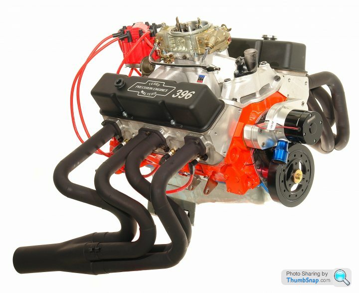
SB Chevy 350. 588 hp – 470 Lbs-ft with all accessories on. 383 609 HP and 531 lbs-ft. 396 607 HP 540 lbs-ft.
 |http://thumbsnap.com/5MpQosnU[/url][url]
BB Chevy 496. 782 hp 682 Lbs-ft. 525 on 87 octane pump gas 734 lbs-ft and 794 hp
 [url]
[url]
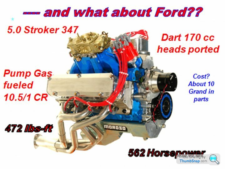
SB Stroker Ford 472 lbs-ft 562 hp.
 |http://thumbsnap.com/Sn5viunP[/url][url]
Idle speeds – small block under 825 with about 11 -12 inches of vacuum
BB idle 650 or less with about 11 -12 inches of vacuum.
These are results on a first time around basis driven entirely by my component combination selection, my head porting and my Cam Master program plus fine tuning on the dyno. The tech that produces these numbers is what I put into my books and seminars.
So here is the point – if your engines do not meet this level of performance first time around ie straight off the drawing board, then maybe you should come to one of my seminars as it will be the cheapest way to get up to speed. If you are doing better then feel free to tell me so I can tell the rest of the world how good you are (no I am not being sarcastic) so I can make you lots of money as a successful engine builder.
Now I have said my piece lets get back to the points that Dave brought up with his original post. How do we reconcile these theoretical vs in practice differences. Well I can guarantee ther is a logical answer – so lets not rely on DB alone here. Lets all put oput 10 Cents worth in here.
First place to start – Dave B’s Peugeot numbers.
So, Dave B, let me have the flow figs, CR, rod length, valve sizes, rocker ratios, valve lift exhaust system spec etc for your Peugeot engine/s and let’s see what Cam Master comes up with. This might reveal a flaw in the program or a problem I have yet to uncover downstream of that when making the graphical simplifications. I am sure between all the switched on PH posters we have this can be figured out???? Throughout this though don’t forget your theory has to fit what happens in practice. You cannot change practice results to fit your theory.
 |http://thumbsnap.com/TwgON3IQ[/url]
As usual, when it comes to theory, Dave Baker strikes with brutal accuracy – the guy is a one man think tank. I make that point because the guy is good at this – real good. That’s why I so often bounce my thoughts off of Dave as he seems to be able to cut to the chase right now. I have also found that if he subsequently is proven wrong on a particular subject it is, in my experience, usually because he was not fed the whole story upon which to base his conclusions. Now I am not saying all this to make Dave feel good but to make it clear that any theory he comes up with needs to be given a great deal of serious consideration.
Now we have that all out the way let me start with my position here – one that – ironically – Dave brought to my attention.
What I have tried to do over the years is to report what I find on the dyno. In the last decade and a half I have tried to translate the dyno finding of about 45 years with a relatively small variety of engines into some kind of universal and simple laws that can be applied across the board by the enthusiast who is not quite as well equipped as I am. Dave said it succinctly in one of his earlier post i.e. I was trying to come up with simple universal laws to cover all situations. Yes - that is exactly true – in fact I have come up with two groups of such – the ones I use with a computer and a ton of math (not really simple)and the ones I give out in much simplified form so almost any engine builder can use it to some advantage - and here is how all that comes about.
Firstly I get on the dyno and test – and test – and test to an almost unbelievable extent. During those tests I change one factor (but without losing the possible influences of other factors) and retest then another and retest. The bulk of the LCA computations that I have developed for my Cam Master program relates to flow Vs cubic inches with the valve size only in the equation for the determination of velocity both at the seats and in the ports and it’s effect on through-flow during overlap.
I must admit I have not fully comprehended DB’s theory on why the valve diameter and displacement have nothing to do with the LCA. That said I can tell you all that the bulk of the LCA determination testing was done on SB Chevy’s, BB Chevys, SB Fords and Pinto engines (Plus anomalies such as the A and B series engines). For the SB Chevy’s I ran a variety of displacements from about 300 inches (5 Litres) to 434 inches (7.1 Litres) but mostly with engines from 306 inches to 406, with heads on having intake valves from 1.84 to 2.125 in diameter. Also I tested with at least 3 CR differences in each displacement of short block. For the smaller displacement engines testing with the higher CR was plagued with the high piston crown causing a potential bad burn (although I did resolve that within reason). That usually involved shaving the heads to the point they had only a minimal life so a perfectly good set of factory ported heads went down the toilet in an hour or so of running. But that’s life.
Along with the displacement Vs valve tests intake valve acceleration scans were done by virtue of a special set of adjustable ratio rockers. (1.45 -1.68). This and one of the early Jesel belt drives meant I had at least a fair number of tests that could be done without tearing the test engine down. So to sum up this barrage of tests we had the following test parameters.
Variables considered:-
Test 3 - 5 cams with LCA’s from 114 to 102 in at least 3 displacements and 3 intake valve sizes.
Test as per above with at least 2 longer duration (single and dual pattern) cams again with 3 - 5 LCA’s.
Test each of above with at least 3 CR’s.
Test each of above with at least 3 rocker ratio’s.
Test most of above with three different rod lengths (5.56, 5.85 and 6.125)
Non Variables:- Engine was equipped with a good exhaust system having 1-5/8th primary’s 33 inches average length and 12 inch X 3 inch secondary.
Intake was a good single plane 4 barrel setup using a Braswell carb that had good booster signal and about 820 cfm of flow.
Essentially all the data and effect curves developed made the assumption that both the intake and exhaust system were effectively functional. That was because I would not be running any of my engines with a poor intake or exhaust.
In all, on the SB Chevy alone, these tests amounted to a little over 8000 saved and useful dyno pulls. (That, like many of the R & D projects I have undertaken took a lot of hard work, time and money and is one of the reasons why I do not have the slightest feeling of guilt to ask for $550 a pop for a seat at one of my seminars.)
So what did all these dyno pulls tell me?
NOW HERE’S WHERE WE GET TO THE DIFFERENCE BETWEEN THEORY/OPINION AND PHYSICAL TEST RESULTS. This is how the cookie crumbles – this is what happened in the real world – use it to your advantage or not – either way it’s your choice. Oh and by the way if you want to repeat the tests be my guest. Call me in a couple of years when you have burned down a few motors and depleted you bank balance significantly.
1) As the cubes got bigger under a fixed head the optimum LCA got tighter. Going from a 302 to a 434 meant a change of typically 6 - 7 degrees. On 350/383 inch test engines 2 degrees too wide typically showed almost 20 hp and 20 lbs-ft loss. A statistic which has repeated itself with many of the pro pushrod V8 engine builders I have worked with.
2) Fixing the bottom end and varying the intake size/flow causes the LCA to get wider when the flow goes up and narrower when it goes down. Not unexpectedly it follows the same characteristics as the previous case. i.e. when the flow/size is the same per cube the best LCA was right around the same. Point to note it is only flow differences within the overlap that have any effect on the LCA. If the flow increases are at high lift and occurs after the exhaust has close it has no really discernable effect on the LCA. In other words any effect it may have is very much a second order effect.
3) As intake valve acceleration goes up so the optimum LCA gets wider. This is not unexpected as the engine only knows flow not lift. In other words the way to determine how much overlap is really functioning is to do a plot of cfm/degree AT THE CYLINDER/PORT PRESSURES THAT ACTUALLY EXIST as opposed to the dreaded 28 inch flow bench deal.
4) As the CR goes up so the LCA needed becomes wider ie the amount of overlap that is presented to the cylinder goes down as the chamber volume goes down (as it would for a higher CR). This factor should be easy to see as the smaller the chamber is the less time/area needed to scavenge it. Note in real life port/cylinder pressure tests indicate that a little over scavenging is what you want if absolute power is the sole target. (yes for ProStock but maybe not for NASCAR where fuel mileage is also a factor).
5) Rod length – this is a second order effect. If we use just basic theory where only the pistons position up the bore is considered it looks to be more of a factor than it really is. When all the side issues such as piston friction, CR and a few other things are taken into account a rod change of 1 inch in a small block Chevy only affects the LCA by a about 1 degree. At very high CR such as in ProStock that number gets even less to the point of being nearly irrelevant.
Summery to here:- All of the above points to a number of things but one to keep in mind that is not quite so obvious from the test results is that it is overlap that is the key to success when it come the valve event timing not, AS IS SO OFTEN SUPPOSED, the intake closing point. The best way to look at this is that if you have not got the first half of the opening event working optimally to fill the cylinder IT DOES NOT MATTER WHAT YOU DO IN THE SECOND HALF IT CAN NEVER – REPEAT – NEVER - BE REDEEMED. It’s like leaving the line too slow at the drag strip making up for it in the second half of the track is nigh on impossible.
Cam advance/retard (intake centerline setting)
Note:- YOU CANNOT DO ANY CAM/HEAD/DISPLACEMENT/ROCKER TESTS WITHOUT AN ADUSTBLE CAM DRIVE! THINK OTHERWWISE AND YOU ARE KIDDING YOURSELF!!! Thank you Mr. Jesel for the hundreds of hours you have saved me and for the superior results I have achieved by using your belt drive.
6) Let’s talk cam advance here. This seems to be a subject that no-one wants to discuss including the cam companies who would have you believe that all you should have to do is set the cam in the engine to their recommended setting and Bingo you have the optimum ‘set in concrete’ cam timing. Guess what – well I think you already have – nothing could be further from the truth. So forget opinions, hearsay and the like. Here is the real story as told by Mr. Dyno Esquire.
7) First let’s assume that you have a regular 350 SB Chevy and the heads are just about as average a deal as you can get. Under these circumstances let’s say that the optimum cam setting is 4 degrees advanced. Advance is the LCA minus the intake centerline at full lift. So on a 108 LCA cam in at 4 degree advance means that the intake valve reaches full lift at 104 degrees after TDC on the intake stroke. Let’s take this as our starting point.
8) If the intake valve in the above case is made to flow much better and the exhaust flow remains unchanged (during the overlap period) then the cam will need to be retarded so as to cut the degrees of opening before TDC. Remember the engine does not recognize lift but it does recognize flow. If the valve flow is worse then the cam needs to be advanced more. (this is why most folk who test 30 degree seats fail to realize anything but a loss even though the low lift flow was dramatically improved – get yourself a belt drive and do the tests properly!)
9) If the intake rocker ratio goes up the amount of flow potential presented to the cylinder goes up and as a consequence the cam must be retarded.
Note:- a little info that is playing into the LCA situation concerns what I am currently doing with new V8 exhaust system technology. Because the exhaust systems I am currently experimenting with are pulling a greater exhaust depression during the overlap I am finding the my current batch of BB Chevy’s are requiring a wider LCA than with a regular Hooker style race exhaust. Also the amount of advance drops by as much as 3 degrees over what would normally be the case.
10) A lazy exhaust, in most cases, usually wants a tighter LCA while an energetic one will want a wider one. As for advance this is still dependant on the flow ratio of intake to exhaust during the overlap period.
Another Note:- a restricted intake is a nightmare to deal with to get accurate computational results. My Cam Master program does not deal with such. When I do cams for restricted motors I usually go from experience. That has worked well so far for me but it is a little difficult to pass on – hence the attempt to put data into a user friendly format such as I do in my books.
11) When we get to blower motors, turboes and nitrous we get to a whole load of extra dimensions. In these area’s I have a fair amount of experience so can compete with the best out there without worrying about breaking into a sweat. That’s the nice part about using a dyno to put forth your thoughts.
12) My motto – I don’t have an opinion – I have a dyno.
OK, so how well, in practice, does all the Cam Master stuff serve me:- Let’s take a few of my latest 10.0 to 10.5/1 pump gas engines and see how the results stack up. As it happens, so I am on the conservative side here, I will use results from Terry Walters dyno in Roanoke (http://www.waltersengines.com). After testing my latest 525 build that was run on the University Of Northwestern Ohio dyno (the one used for the Engine masters Challenge – EMC) we found that Terry’s dyno reads 715 lbs-ft where as the University one reads 730. So if you are going to make a comparison with the EMC entrants I want you to bear this in mind and the fact that the motors I am about to quote are ones that will go out of Terry’s shop with a very healthy mileage/time warranty. So here are some numbers for engines where the cam spec was frozen right from the point it was computed on my Cam Master program.
SB Chevy 350. 588 hp – 470 Lbs-ft with all accessories on. 383 609 HP and 531 lbs-ft. 396 607 HP 540 lbs-ft.
|http://thumbsnap.com/5MpQosnU[/url][url]BB Chevy 496. 782 hp 682 Lbs-ft. 525 on 87 octane pump gas 734 lbs-ft and 794 hp
[url]SB Stroker Ford 472 lbs-ft 562 hp.
|http://thumbsnap.com/Sn5viunP[/url][url]Idle speeds – small block under 825 with about 11 -12 inches of vacuum
BB idle 650 or less with about 11 -12 inches of vacuum.
These are results on a first time around basis driven entirely by my component combination selection, my head porting and my Cam Master program plus fine tuning on the dyno. The tech that produces these numbers is what I put into my books and seminars.
So here is the point – if your engines do not meet this level of performance first time around ie straight off the drawing board, then maybe you should come to one of my seminars as it will be the cheapest way to get up to speed. If you are doing better then feel free to tell me so I can tell the rest of the world how good you are (no I am not being sarcastic) so I can make you lots of money as a successful engine builder.
Now I have said my piece lets get back to the points that Dave brought up with his original post. How do we reconcile these theoretical vs in practice differences. Well I can guarantee ther is a logical answer – so lets not rely on DB alone here. Lets all put oput 10 Cents worth in here.
First place to start – Dave B’s Peugeot numbers.
So, Dave B, let me have the flow figs, CR, rod length, valve sizes, rocker ratios, valve lift exhaust system spec etc for your Peugeot engine/s and let’s see what Cam Master comes up with. This might reveal a flaw in the program or a problem I have yet to uncover downstream of that when making the graphical simplifications. I am sure between all the switched on PH posters we have this can be figured out???? Throughout this though don’t forget your theory has to fit what happens in practice. You cannot change practice results to fit your theory.
|http://thumbsnap.com/TwgON3IQ[/url]Edited by David Vizard on Sunday 5th February 22:44
DV, thank you for your detailed response to the issues raised in this thread. I'll get back on this once I've had time to compose a comprehensive reply with graphs and maths. Firstly though I'm not doubting your empirical results on Chevy engines and those with similar cylinder sizes albeit I don't have the data to study. However I'll reiterate my thoughts on why CID/inch doesn't affect LSA.
When we go from very large 2v cylinders (24 CID/inch of valve diameter) to very small 4v ones (4 CID/inch) the LSA stays essentially invariant. It's always in the region of 105 degrees plus or minus a few degrees. If we can change the CID/inch by a factor of 6 and the LSA doesn't alter much then we MUST conclude that the two are not related.
To fully answer all this we have to perform the scientific method of extrapolating to extremes. We must consider engine designs at opposite ends of the spectrum and then see if those in the middle fit any theory.
In considering all this I took three situations.
1) Taking a 2v engine and comparing it to a 4v engine with the same valve area per cc. i.e. one engine had a single large inlet valve of diameter X and the other had the same bore and stroke and two smaller inlet valves of diameter X / 1.414 (root 2). Both engines have similar peak flow but the 4v engine has 1.414 times the low lift flow. The LSA stayed constant.
2) Changing the bottom end capacity under a given cylinder head. The LSA stayed constant.
3) Increasing the cam duration radically in a given engine. The LSA stayed constant.
I'll work through the maths in due course.
If Chevy (or other V8) engines need different LSAs as the capacity varies then we need to find a real reason as the CID/inch variable doesn't fit the theory or the empirical results.
If you want a single factor to think about before I respond fully it's time. As engine rpm increases time to do anything decreases. Put a bigger bottom end under a given cylinder head and rpm at peak power decreases and time per cycle increases. The overlap triangle is not just a matter of flow area it's a matter of time for that flow to take place. That single factor cancels out most of the effects you believe make CID/inch a determinant in specifying LSA.
Once I've run through all the maths you'll see why time is the single biggest factor in determining ideal LSA and how it cancels out all the other factors and why LSA stays pretty much invariant.
DB post.---- Taking a 2v engine and comparing it to a 4v engine with the same valve area per cc. i.e. one engine had a single large inlet valve of diameter X and the other had the same bore and stroke and two smaller inlet valves of diameter X / 1.414 (root 2). Both engines have similar peak flow but the 4v engine has 1.414 times the low lift flow. The LSA stayed constant.
Dave,
you have to look more at the valve circumference of the single vs the two intakes not the area as this does not figure into the overlap situation.
DV
Dave,
you have to look more at the valve circumference of the single vs the two intakes not the area as this does not figure into the overlap situation.
DV
Gassing Station | Engines & Drivetrain | Top of Page | What's New | My Stuff