Chevy LS1 alternator wiring?
Discussion


I have an LS1 going into a kitcar.
I have an alternator wiring diagram showing me the pinout of the plug as:-
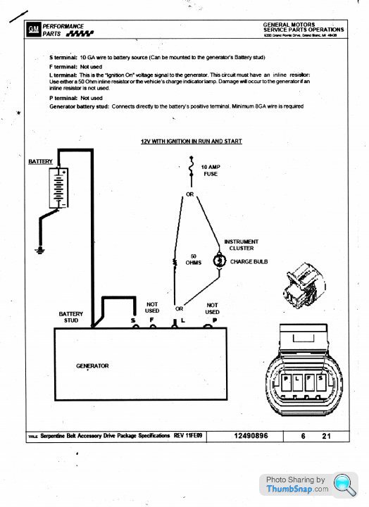
S – Connects to the main power terminal of the alternator.
F – Not used
L – Connects to either a resistor from a +12V ignition supply or a charge lamp also from a +12V ignition supply.
P – Not used.
I also have a pinout listing for the engine ECU which tells me R15 is ‘Generator Turn ON Signal Terminal L’. I’m also told that this ECU connection is one of many that have to be in place for the engine to run.
I want to use a dash mounted charge warning lamp so can anyone tell me if I can leave this ECU pin disconnected?
Thanks
Steve
I have an alternator wiring diagram showing me the pinout of the plug as:-
S – Connects to the main power terminal of the alternator.
F – Not used
L – Connects to either a resistor from a +12V ignition supply or a charge lamp also from a +12V ignition supply.
P – Not used.
I also have a pinout listing for the engine ECU which tells me R15 is ‘Generator Turn ON Signal Terminal L’. I’m also told that this ECU connection is one of many that have to be in place for the engine to run.
I want to use a dash mounted charge warning lamp so can anyone tell me if I can leave this ECU pin disconnected?
Thanks
Steve
Steve_D said:
I have an LS1 going into a kitcar.
I have an alternator wiring diagram showing me the pinout of the plug as:-
S – Connects to the main power terminal of the alternator.
F – Not used
L – Connects to either a resistor from a +12V ignition supply or a charge lamp also from a +12V ignition supply.
P – Not used.
I also have a pinout listing for the engine ECU which tells me R15 is ‘Generator Turn ON Signal Terminal L’. I’m also told that this ECU connection is one of many that have to be in place for the engine to run.
I want to use a dash mounted charge warning lamp so can anyone tell me if I can leave this ECU pin disconnected?
Thanks
Steve
LS1 has been around for a veyr long time now, and with many different alternators depending what vehicle it was fitted to.I have an alternator wiring diagram showing me the pinout of the plug as:-
S – Connects to the main power terminal of the alternator.
F – Not used
L – Connects to either a resistor from a +12V ignition supply or a charge lamp also from a +12V ignition supply.
P – Not used.
I also have a pinout listing for the engine ECU which tells me R15 is ‘Generator Turn ON Signal Terminal L’. I’m also told that this ECU connection is one of many that have to be in place for the engine to run.
I want to use a dash mounted charge warning lamp so can anyone tell me if I can leave this ECU pin disconnected?
Thanks
Steve
So there isnt going to be a generic wiring how to...without knowing exactly what unit you have. And many will have the same 4 pin plug....but various wiring options.
If the ECU instructions say R15 must be connected to ‘L’ or the engine will not run, better connect it. It will just be an ignition switched battery voltage output but monitored by the software. ‘L’ is the exciter connection to start up the alternator. Nothing to stop you running an additional ignition switched connection to ‘L’ through a charge lamp. (Ask the ECU manufacturer if you could put the charge lamp in the line from R15.)
The S connection is for the System Voltage Sensing wire to enable the regulator to function. This should be fed from a point registering reduced voltage when loads are ON. If connected to the alternator output, the regulator will only sense the static default output and will not increase output to compensate for loads or voltage drop between alternator and battery. The battery will be depleted. Most sources (e.g. Toyota at http://wilbo666.pbworks.com/w/page/39441708/Toyota... , scroll down) recommend connecting at or near the battery +ve terminal but see extract from http://www.pirate4x4.com/tech/billavista/Wiring/Pa... that suggests connecting nearer to vehicle loads.
Pirate 4x4. Assume the alternator's voltage regulator is "set" to 14.0 volts. If we "sense" system voltage (i.e. hook up the alternator's voltage sensing terminal) right at the alternator output , we are going to get a value equal to the alternator's output say 14.0 volts. Now, the voltage regulator says to itself "I'm supposed to produce an output sufficient to maintain system voltage at 14.0 volts. I sense system voltage (at my output terminal) as 14.0 volts. Everything OK, maintains this level of output."
Meanwhile - 12 feet away the power-hungry amplifiers are only getting 13.0 volts because of the voltage drop that occurs in the wiring from the alternator to the main bus bar and on to the amps. It's even worse for components further "downstream" from the bus bar. But the alternator has no way of knowing this - because we hooked the voltage sensing wire right to the alternator output - it thinks everything is fine, it thinks system voltage is at 14.0 volts and it has no idea about the low voltage at the amps.
Doing this - sensing voltage at the alternator output - seriously hamstrings the system - it's like a self-fulfilling system - it's supposed to maintain 14.0 volts, it outputs 14.0 volts, therefore everything must be OK, right? But it completely ignores voltage drop in the rest of the system.
This is where the concept of REMOTE voltage sensing comes into play. Instead of sensing system voltage at the alternator or close to it (which is like congratulating yourself on a great job regardless of the results!) - we sense system voltage where we need full voltage - in this case at the main distribution point (bus bar).
That way, when the voltage sensing circuit detects 13.0 volts at the main bus bar, it says: " I'm supposed to produce and output sufficient to maintain system voltage at 14.0 volts. I sense system voltage as 13.0 volts. Better increase output to 15.0 volts to bring system voltage up to 14.0 volts."
John McL
Edited by JohnMcL on Sunday 15th January 01:04
Edited by JohnMcL on Sunday 15th January 01:37
Ignore any comments about other makes or brands of alternators, they mean little here.
Find what your EXACT model needs for the exact vehicle it was fitted to and ecu it was using. If you are not using the original chassis, original ecu....then clearly things will be different.
But trying to compare it to a completely different alternator like a Toyota...makes no sense.
You may get more info here....but once again, you will need to know the exact model/year/chassis the unit came from. Otherwise you're just guessing and wrong connections could blow it up. Although replacement parts for them are fairly cheap. Any local alternator repair shop should be able to get them, or probably advise of what connections may need used in order to charge. Whether that's enough for whatever your application is though, they wont know
http://ls1tech.com/forums/conversions-hybrids-28/
Thanks for the replies.
The sensing wire is logical but as you can see from this GM diagram it quite clearly says connect it to the power terminal.
I know the engine is 2002 but I have no idea which model car it belongs to.
Will get a part number off it in the morning and see if that helps.
Steve
The sensing wire is logical but as you can see from this GM diagram it quite clearly says connect it to the power terminal.
I know the engine is 2002 but I have no idea which model car it belongs to.
Will get a part number off it in the morning and see if that helps.
Steve
Steve_D said:
Thanks for the replies.
The sensing wire is logical but as you can see from this GM diagram it quite clearly says connect it to the power terminal.
I know the engine is 2002 but I have no idea which model car it belongs to.
Will get a part number off it in the morning and see if that helps.
Steve
If you read the notes it actually recommends a "10GA wire to the battery source" but says the sense terminal can also be mounted to the generator output stud.The sensing wire is logical but as you can see from this GM diagram it quite clearly says connect it to the power terminal.
I know the engine is 2002 but I have no idea which model car it belongs to.
Will get a part number off it in the morning and see if that helps.
Steve
The first unit I started with was circa 2001. It lived a long happy live with a single wire connected to the dash bulb for the alternator.
If you were standing looking at the front of the engine, with the alternator low down and to your right, the pin I connected to was the 3rd pin counting left to right.
But again....given how many different models of car these engines were fitted to, there were many variations. What worked on one year, may not work on another etc.
Bit more research has brought up info that the ECU (PCM) will throw codes if it is not seeing the alternator so it looks like this car will have to go without an ignition light. In the original Chevy car the driver information centre would report charging faults so no need for a light.
I think I will extend the sensing wire up to the battery as this car is mid engine with the battery up front.
Thanks again for the help.
Steve
I think I will extend the sensing wire up to the battery as this car is mid engine with the battery up front.
Thanks again for the help.
Steve
Gassing Station | Engines & Drivetrain | Top of Page | What's New | My Stuff