Fuel Pump speed control
Discussion


===========
"able to detect changes in demand before change in rail pressure is realized"
Which sounds good, but breaks the laws of physics. If it can actually do that, then it can also tell me what next weeks (week’s ?) winning Lottery numbers are ;-)
What that regulator does is simply to measure the position (height off the seat) of the regulators (regulator’s?) fluid valve orifice. The PWM pump controller then reads that position and drives the fuel pump in such a fashion as to attempt to keep that height constant. This is fundamentally a good halfway house to minimising return flow, without getting into the much more complex controls work required for a full returnless system. But what it can't do is realise a change in flow BEFORE the pressure changes!!
==========
MT’s comments above have helped clarify things. The other points about Weldon’s controller are to be expected, a pity they offer such a limited product while their pumps seem quite good.
The Fuelab assessment is less clear. I understand that Fuelab do not claim to realise a change in flow before the pressure changes but a change in demand. Is this because MAP is monitored too?
Anyway, I do not want a full returnless system if an aftermarket solution involves control complexity, cost and the hassle of calibration when I may have a 95% solution decently made at reasonable cost from a respected supplier. I suspect that goes for many others too.
Anyone have other suggestions for products that might suit?
Could the controller not also monitor MAP so it can increase pump speed at the same time as air demand is increased? That should minimise the change in fuel pressure as the pump speed is mapped to the Load rather than just line pressure.
You could still monitor line pressure and make fine adjustments to pump speed.
This would also allow you to run a variable rail pressure based off what the demands are. Guessing this would be useful in a boosted application where it's nice to increase rail pressure in line with boost pressure.
EDIT: actually read John's post above. The only way in a see is if the pump controller is monitoring the MAP.
Edited by chuntington101 on Saturday 8th August 17:54
Steve_D said:
In my case I have a pump large enough to support the 500hp engine which then is noisy when driving around town and puts so much fuel round the system that it very quickly gets too hot.
Steve
What fuel temperatures are you seeing ?Steve
I've pumps running all the time enough to support 1500hp. I've never had an issue even driving for 250miles at a time ( need to refuel after that )
500hp pump isnt huge by any stretch and certainly the pump itself will add very little heat to the fuel.
stevieturbo said:
Steve_D said:
In my case I have a pump large enough to support the 500hp engine which then is noisy when driving around town and puts so much fuel round the system that it very quickly gets too hot.
Steve
What fuel temperatures are you seeing ?Steve
I've pumps running all the time enough to support 1500hp. I've never had an issue even driving for 250miles at a time ( need to refuel after that )
500hp pump isnt huge by any stretch and certainly the pump itself will add very little heat to the fuel.
How about this one Professional Prodcuts Fuel-On-Demand Fuel Pump Controller
Steve
Edited by Steve_D on Saturday 8th August 21:37
I've seen it before, and Vaporworx, Squash etc Never used any though
But really...if hot fuel is a problem for you ( but you'd need to monitor it first ), fit a fuel cooler. It will be by far the strongest solution, even more so given you're saying there is so much heat around heating the fuel.
Slowing down fuel movement if the entire system is surrounded by heat..isnt really going to fix anything.
The pump itself imparts very little heat compared to the hot environment around the system. So whether that fuel is moving fast or slow...it's still going to heat up.
I wonder if the expension due to hot fuel is enough to have any noticeable effect on AFR?
If I was at work I could calculate it, but I'm not.
So if you mapped it with fuel at say 40C at the rail, at 50C the fuel density will have dropped by what percentage?
If I remember, I'll work it out tomorrow.
If I was at work I could calculate it, but I'm not.
So if you mapped it with fuel at say 40C at the rail, at 50C the fuel density will have dropped by what percentage?
If I remember, I'll work it out tomorrow.
AW111 said:
I wonder if the expension due to hot fuel is enough to have any noticeable effect on AFR?
If I was at work I could calculate it, but I'm not.
So if you mapped it with fuel at say 40C at the rail, at 50C the fuel density will have dropped by what percentage?
If I remember, I'll work it out tomorrow.
I was looking at this at work recently also. Considering clear Indoline, references suggested that ~10% of gasoline is in a vapour state at 25°C but increasing to ~90% vapour state by 170°C!If I was at work I could calculate it, but I'm not.
So if you mapped it with fuel at say 40C at the rail, at 50C the fuel density will have dropped by what percentage?
If I remember, I'll work it out tomorrow.
Max_T, back on your/my systems. Now we have done away with a fuel pump relay, how (have you?) programmed a fuel pump prime on Ign key turn? I was thinking of fitting a momentary switch to the wheel/dash which I can use as a digital input to ECU which then forces PWM signal to the pump to go to full output while the button is depressed?
I was envisaging this could also be useful for draining the fuel tank using the pump if required also..?
Pat_T said:
Max_T, back on your/my systems. Now we have done away with a fuel pump relay, how (have you?) programmed a fuel pump prime on Ign key turn? I was thinking of fitting a momentary switch to the wheel/dash which I can use as a digital input to ECU which then forces PWM signal to the pump to go to full output while the button is depressed?
I was envisaging this could also be useful for draining the fuel tank using the pump if required also..?
As my system is using my own pump controller i have full control over strategy, so i have a key-on prime period which also incorporates a fluid system integrity check and pump characterization, and low pressure hold during KeyOnEngineOff. I also have a "NO RUN" switch input (allows engine to be cracked without fuel pressure) and a "PRIME / PURGE" input to allow system bleed down or initial rail filling etc. KeyOnEngineOn running, the system does a continuous leak check, and monitors pump performance and reports available flow headroom to the EMS.I was envisaging this could also be useful for draining the fuel tank using the pump if required also..?
If you are still running with a returnline and mech regulator, then yes a "got to 100%" input will work fine

Max_T and anyone else still following this thread.
My loom was completed and installed.

and today we sent a good 8 hours on Pi CalTool starting to set up the Pectel SQ6 calibrations.
And we have success, I can confirm that with a 12-14V feed and a 60-330Hz PWM signal you can control the Fuel Pump speed through the Jag VDO driver module previously discussed which I purchased for the princely £15!
It turns out Caltool has some really extensive options for PWM control of a a Fuel Pump. I will try to get a screengrab later this weekend, but in summary it has built in parameters for fully closed loop PID control to a target rail pressure
Engine fire not far away hopefully...
My loom was completed and installed.
and today we sent a good 8 hours on Pi CalTool starting to set up the Pectel SQ6 calibrations.
And we have success, I can confirm that with a 12-14V feed and a 60-330Hz PWM signal you can control the Fuel Pump speed through the Jag VDO driver module previously discussed which I purchased for the princely £15!
It turns out Caltool has some really extensive options for PWM control of a a Fuel Pump. I will try to get a screengrab later this weekend, but in summary it has built in parameters for fully closed loop PID control to a target rail pressure
Engine fire not far away hopefully...
Max_Torque said:
stevieturbo said:
Can you use a solid state relay to PWM the pumps ?
Not ideally, because you really need synchronous rectification at these currents, or the losses increase massively, as do the electrical noise/ EMC emissions (because of the sharp turn off during the reverse recovery of the passive freewheeling diode.Nice one! Sounds like it's all coming together!
RE:SSRs - why? As PatT demonstrates, for less money you can just buy a pump speed control module that is designed to do the job and is available in an emergency from any ford or jaguar dealer, or any breakers yard in the country pretty much.
RE:SSRs - why? As PatT demonstrates, for less money you can just buy a pump speed control module that is designed to do the job and is available in an emergency from any ford or jaguar dealer, or any breakers yard in the country pretty much.
Max_Torque said:
Nice one! Sounds like it's all coming together!
RE:SSRs - why? As PatT demonstrates, for less money you can just buy a pump speed control module that is designed to do the job and is available in an emergency from any ford or jaguar dealer, or any breakers yard in the country pretty much.
Has anyone confirmed what sort of current they can handle ?RE:SSRs - why? As PatT demonstrates, for less money you can just buy a pump speed control module that is designed to do the job and is available in an emergency from any ford or jaguar dealer, or any breakers yard in the country pretty much.
Whilst I havent tried to use it yet....cheap Chinese crap is available everywhere.
Any major downsides to the likes of this ? ( other than it being cheap Chinese crap lol )
http://www.amazon.co.uk/JGX-40DD-Covered-Solid-Mod...
stevieturbo said:
Has anyone confirmed what sort of current they can handle ?
That VDO driver uses the Infineon BTS282z N channel mosfet (with integrated temp sensor) as it's switching device:BTS282z-datasheet
It has an RDSon of about 8mOhm. So at 10A, that's 0.8W dissipation, and at 20A, 3.2Watts.
It has a peak junction temp of 175degC, so for a say 40degC ambient, thats a temp rise of 135degC.
To stay within peak temp limit at 20A, it would need to have a maximum thermal resistance to ambient of 42K/W
The datasheet suggests that it meets that requirement when mounted on a 6cm^2 heatsink. In the case of the VDO module, it is mounted on a thick steel heatsink, that is then coupled to the ally case the device is enclosed in.
You could massively improve the thermal performance by mounting either a heat sink right on top of the case, or by mounting the case to a large ally or steel panel, using heat sink compound to span the gap.
I can't see any obvious external (to the driver chip) current sensing shunt resistor, so it looks like the units maximum current is just set by the thermal performance of the driver IC.
However, rather surprisingly, the unit doesn't do synchronous rectification, but uses a fast rectifier diode for that, a STPS10L60D POWER SCHOTTKY RECTIFIER, which is rated at 10 amps continuous. But it worth noting that the current only flows through this device when the power switch is OFF, so as duty cycle increases, the average current falls.
In reality, it is probably the rectifier diode that is the limiting factor (rather than the power switch) and as such, i would expect, as std it would fairly easily manage 15A continuously. As the rectifier is a "dumb" two terminal device, it would be simple to switch it out for a higher rated version (like the Vishay VT4045BP, rated at 40A).
Max_Torque said:
That VDO driver uses the Infineon BTS282z N channel mosfet (with integrated temp sensor) as it's switching device:
BTS282z-datasheet
It has an RDSon of about 8mOhm. So at 10A, that's 0.8W dissipation, and at 20A, 3.2Watts.
It has a peak junction temp of 175degC, so for a say 40degC ambient, thats a temp rise of 135degC.
To stay within peak temp limit at 20A, it would need to have a maximum thermal resistance to ambient of 42K/W
The datasheet suggests that it meets that requirement when mounted on a 6cm^2 heatsink. In the case of the VDO module, it is mounted on a thick steel heatsink, that is then coupled to the ally case the device is enclosed in.
You could massively improve the thermal performance by mounting either a heat sink right on top of the case, or by mounting the case to a large ally or steel panel, using heat sink compound to span the gap.
Max_T, thanks for this good info. I currently have it in the engine bay but as far from the heat sources as I could get it. It's mounted to fibreglass so heatsink is difficult, but it's wrapped in gold foil, and I could easily give it a dedicated cold air feed if I started to have problems. I think my pump will only pull around 8-9A at 3-4bar anyway.BTS282z-datasheet
It has an RDSon of about 8mOhm. So at 10A, that's 0.8W dissipation, and at 20A, 3.2Watts.
It has a peak junction temp of 175degC, so for a say 40degC ambient, thats a temp rise of 135degC.
To stay within peak temp limit at 20A, it would need to have a maximum thermal resistance to ambient of 42K/W
The datasheet suggests that it meets that requirement when mounted on a 6cm^2 heatsink. In the case of the VDO module, it is mounted on a thick steel heatsink, that is then coupled to the ally case the device is enclosed in.
You could massively improve the thermal performance by mounting either a heat sink right on top of the case, or by mounting the case to a large ally or steel panel, using heat sink compound to span the gap.
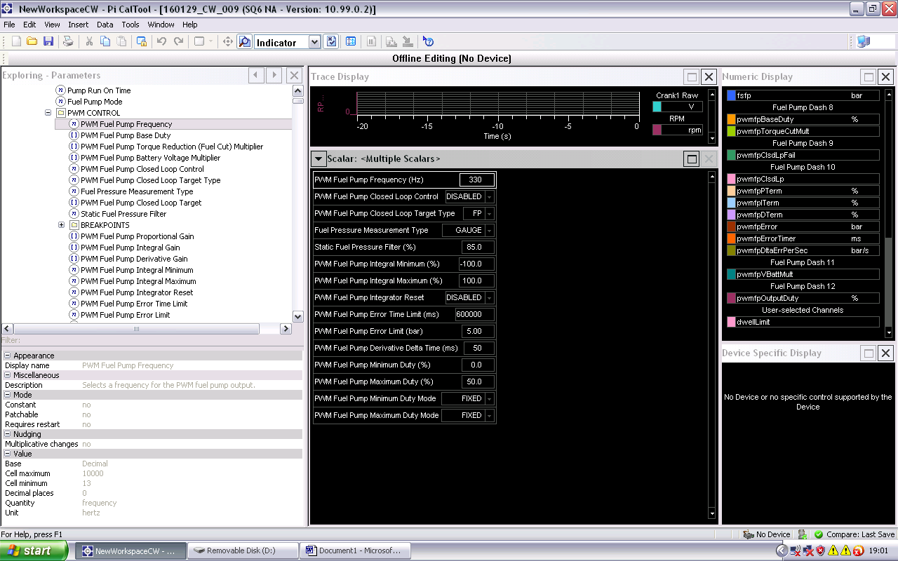
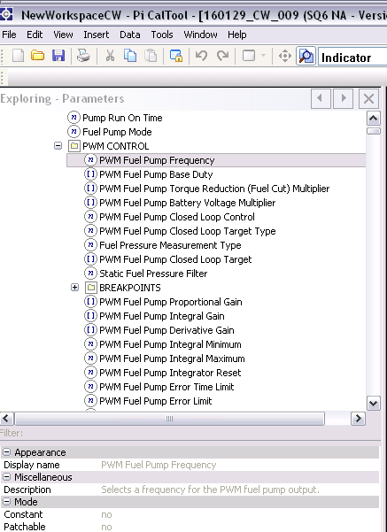
As promised, couple of screengrabs of the available PWM control parameters in the latest code Version of Pi CalTool:
Suspect I may well be back here soon asking about suggested starting points for some of these values once we get the engine started and a bit further along with things. By the way I renamed the blog http://ferotus.blogspot.co.uk/ if the previous links are now broken.
cheers,
Patrick
Pat_T said:
Max_Torque said:
That VDO driver uses the Infineon BTS282z N channel mosfet (with integrated temp sensor) as it's switching device:
BTS282z-datasheet
It has an RDSon of about 8mOhm. So at 10A, that's 0.8W dissipation, and at 20A, 3.2Watts.
It has a peak junction temp of 175degC, so for a say 40degC ambient, thats a temp rise of 135degC.
To stay within peak temp limit at 20A, it would need to have a maximum thermal resistance to ambient of 42K/W
The datasheet suggests that it meets that requirement when mounted on a 6cm^2 heatsink. In the case of the VDO module, it is mounted on a thick steel heatsink, that is then coupled to the ally case the device is enclosed in.
You could massively improve the thermal performance by mounting either a heat sink right on top of the case, or by mounting the case to a large ally or steel panel, using heat sink compound to span the gap.
Max_T, thanks for this good info. I currently have it in the engine bay but as far from the heat sources as I could get it. It's mounted to fibreglass so heatsink is difficult, but it's wrapped in gold foil, and I could easily give it a dedicated cold air feed if I started to have problems. I think my pump will only pull around 8-9A at 3-4bar anyway.BTS282z-datasheet
It has an RDSon of about 8mOhm. So at 10A, that's 0.8W dissipation, and at 20A, 3.2Watts.
It has a peak junction temp of 175degC, so for a say 40degC ambient, thats a temp rise of 135degC.
To stay within peak temp limit at 20A, it would need to have a maximum thermal resistance to ambient of 42K/W
The datasheet suggests that it meets that requirement when mounted on a 6cm^2 heatsink. In the case of the VDO module, it is mounted on a thick steel heatsink, that is then coupled to the ally case the device is enclosed in.
You could massively improve the thermal performance by mounting either a heat sink right on top of the case, or by mounting the case to a large ally or steel panel, using heat sink compound to span the gap.
As promised, couple of screengrabs of the available PWM control parameters in the latest code Version of Pi CalTool:
Suspect I may well be back here soon asking about suggested starting points for some of these values once we get the engine started and a bit further along with things. By the way I renamed the blog http://ferotus.blogspot.co.uk/ if the previous links are now broken.
cheers,
Patrick
Regarding the cal params, if you're not using any feedforward (open loop) table and are using the Integrator to provide the steady state duty, limit the positive integrator to 50% max (as 50% duty = full speed) and the negative integrator to zero (as the system is not bi-polar). To make life easier to start with, i'd set the derivative to zero, and then carry out the usual Proportional tuning steps to find the point the system oscillates. As the system has no way to lower fuel pressure, you don't want the system getting hung up on a clipped negative integrator. (the pump can only increase fuel pressure, the only way to drop it is to use fuel, ie inject it, so overpressure spikes cannot be compensated further than a zero duty output.
Gassing Station | Engines & Drivetrain | Top of Page | What's New | My Stuff