Fuel Pump speed control
Discussion


Max_Torque said:
Regarding the cal params, if you're not using any feedforward (open loop) table and are using the Integrator to provide the steady state duty, limit the positive integrator to 50% max (as 50% duty = full speed) and the negative integrator to zero (as the system is not bi-polar). To make life easier to start with, i'd set the derivative to zero, and then carry out the usual Proportional tuning steps to find the point the system oscillates. As the system has no way to lower fuel pressure, you don't want the system getting hung up on a clipped negative integrator. (the pump can only increase fuel pressure, the only way to drop it is to use fuel, ie inject it, so overpressure spikes cannot be compensated further than a zero duty output.
Starting to look at the PID control now.I'm not using any feedforward table (not sure if software even supports use) and have set the max and minimum outputs.
One thing I am unsure of though:
I am retaining the adjustable FPR (for now) which I have set to ~3.1bar FP (referenced to MAP) and I am setting the SetPoint of my system to 2.99bar FP (pressure sensor also referenced to common MAP takeoff as FPR). This means all overshoots on the positive side will be trimmed to a maximum error of 0.11 bar?
How should I consider this when tuning the system? My gut feel is it should allow me a more responsive system, with only 50% of the overshoots (the lower ones) that I would otherwise get without the FPR..?
As both FPR and ECU see the exact same MAP, can I get away with setting the FPR even closer to the set point?
I am finding this a useful beginner's guide:
http://innovativecontrols.com/blog/basics-tuning-p...

cheers,
Pat
Max_Torque said:
I spent a hr or two this afternoon on a little bit of mapping, with encouraging results:
A nice crisp MAP signal:

(turns out the multi-MAP box is very easy to set up, just 1 parameter to tune (the offset crank angle between the CAM sensor signal "edge" and TDC no1 cyl (and in fact, you don't even have to work this out, just idle the engine and swing the cal parameter around slowly until the MAP signal reads the lowest value - job done!))
and a 1st cut cal for the injector delta pressure compensation table in my MoTec ecu:

(note, rail pressure is varied from 2 to 9 bar with only a small change in exhaust lambda (approx 0.08, and i reckon with a bit of finessing i can get that to better than 0.05 lambda ;-)
I can't think of too many other fuel systems that would deal with a 7 bar swing in rail pressure so undramatically!
Looking at the pump data, it actually seems that it would be possible to have a returnless system with no external sensors required at all. The data shows a pretty much perfect correlation between pump current and rail pressure. So putting the FP controller into closed loop current mode would just force it to hold a given pressure whatever the flow. (the problem being if anything in the system changes or wears (like the pumps themselves) it would have no way of telling that had occurred. For most people, i suspect the cost / complexity of a Rail pressure sensor would be worth paying (and the system could always resort to "open loop" if that sensor failed))
Soooooo dragging up this... Im swopping out my Motec M800 ecu for an M150 and am going ITB with dual DBW... The M150 uses ONLY MAP controls or fuel as it works differently to old 100 series Motec units, I effectively have 2 options, use MAP sensor or use estimated MAP based on throttle x RPM tables etc.A nice crisp MAP signal:
(turns out the multi-MAP box is very easy to set up, just 1 parameter to tune (the offset crank angle between the CAM sensor signal "edge" and TDC no1 cyl (and in fact, you don't even have to work this out, just idle the engine and swing the cal parameter around slowly until the MAP signal reads the lowest value - job done!))
and a 1st cut cal for the injector delta pressure compensation table in my MoTec ecu:
(note, rail pressure is varied from 2 to 9 bar with only a small change in exhaust lambda (approx 0.08, and i reckon with a bit of finessing i can get that to better than 0.05 lambda ;-)
I can't think of too many other fuel systems that would deal with a 7 bar swing in rail pressure so undramatically!
Looking at the pump data, it actually seems that it would be possible to have a returnless system with no external sensors required at all. The data shows a pretty much perfect correlation between pump current and rail pressure. So putting the FP controller into closed loop current mode would just force it to hold a given pressure whatever the flow. (the problem being if anything in the system changes or wears (like the pumps themselves) it would have no way of telling that had occurred. For most people, i suspect the cost / complexity of a Rail pressure sensor would be worth paying (and the system could always resort to "open loop" if that sensor failed))
Edited by Max_Torque on Monday 8th August 20:36
Edited by Max_Torque on Monday 8th August 20:38
I really want to use MAP if i can, but only if its accurate, I was planning to buy a balancing chamber as below but its still not 'ideal' (although i need it for brake and fuel vacuum anyhow i guess)... seems you are again the only person out there that has built a proper solution... Was it effective?
http://bloxracing.com/shop/index.php?route=product...
Pat_T said:
Max_Torque said:
Regarding the cal params, if you're not using any feedforward (open loop) table and are using the Integrator to provide the steady state duty, limit the positive integrator to 50% max (as 50% duty = full speed) and the negative integrator to zero (as the system is not bi-polar). To make life easier to start with, i'd set the derivative to zero, and then carry out the usual Proportional tuning steps to find the point the system oscillates. As the system has no way to lower fuel pressure, you don't want the system getting hung up on a clipped negative integrator. (the pump can only increase fuel pressure, the only way to drop it is to use fuel, ie inject it, so overpressure spikes cannot be compensated further than a zero duty output.
Starting to look at the PID control now.I'm not using any feedforward table (not sure if software even supports use) and have set the max and minimum outputs.
One thing I am unsure of though:
I am retaining the adjustable FPR (for now) which I have set to ~3.1bar FP (referenced to MAP) and I am setting the SetPoint of my system to 2.99bar FP (pressure sensor also referenced to common MAP takeoff as FPR). This means all overshoots on the positive side will be trimmed to a maximum error of 0.11 bar?
How should I consider this when tuning the system? My gut feel is it should allow me a more responsive system, with only 50% of the overshoots (the lower ones) that I would otherwise get without the FPR..?
As both FPR and ECU see the exact same MAP, can I get away with setting the FPR even closer to the set point?
I am finding this a useful beginner's guide:
http://innovativecontrols.com/blog/basics-tuning-p...
cheers,
Pat
1) you can set it close to the target pressure, and always have a small "leak" meaning the fuel system will prime easily and have a small amount of fuel being re-circulated, which will help hot restarting. It also will make your calibration less sensitive, as too much pump work just opens the mech reg a bit more, so rail pressure will be clipped. However, you may find the mech reg a bit "sticky" and depending on the spring rate and how well it seals (most mech regs do not fully seal when "closed") you may find you need to keep an amount of pump duty there the whole time to maintain rail pressure
2) you can set it up out of the way, and just use it to prevent large overshoots, typically cause by integrator windup etc.
One thing i did when calibrating my returnless system was to make a fuel return rail so i could drive my injectors to inject fuel into this rail that just allowed the fuel to flow straight back to the tank. I then used the injector test function in my Motec ECU to experiment with the response of various control system calibrations to step changes in fuel flow (positive and negative) This can all be done with the engine not running, and will get you a good start on the base cal before you need to run the engine.
andygtt said:
seems you are again the only person out there that has built a proper solution... Was it effective?
My "multimap" system works beautifully! As of course it should as it measures the intake system pressure just prior to IVC, which is generally a pretty close approximation of chamber charge density!Max_Torque said:
andygtt said:
seems you are again the only person out there that has built a proper solution... Was it effective?
My "multimap" system works beautifully! As of course it should as it measures the intake system pressure just prior to IVC, which is generally a pretty close approximation of chamber charge density!andygtt said:
Max_Torque said:
andygtt said:
seems you are again the only person out there that has built a proper solution... Was it effective?
My "multimap" system works beautifully! As of course it should as it measures the intake system pressure just prior to IVC, which is generally a pretty close approximation of chamber charge density!Steve
Good point Steve, will look into that.
If i can't get something like Max has Im planning to take MAP into the M1 from 3 separate sensors, 1 linked per bank after the throttle bodies and 1 from the plenum. Its running DBW motor per bank so should be plenty of flexibility.... I had maxed all the pins out on the M800, but on the M150 I find myself with plenty of sensor inputs available to monitor stuff like exhaust pressure and turbo speed etc
If i can't get something like Max has Im planning to take MAP into the M1 from 3 separate sensors, 1 linked per bank after the throttle bodies and 1 from the plenum. Its running DBW motor per bank so should be plenty of flexibility.... I had maxed all the pins out on the M800, but on the M150 I find myself with plenty of sensor inputs available to monitor stuff like exhaust pressure and turbo speed etc
The issue you'll find is that most std MAP sensors designed to read the pressure in a plenum are heavily damped in their output. They typically only have a 20 to 50Hz bandwidth, because normally the pressure in a plenum doesn't change very fast.
You also need to be very careful in the length and volume of your pipework between the runners and the sensor, as you can introduce unwanted resonances and delay / filtering of the pressure wave / signal.
At the moment i only have a four channel multimap sensor unit, although i guess you could just pick 4 runners out of 6 and average the result?
I was planning to monitor at least 2 MAP so I could use 2 of them and only monitor 3 cylinders?... Im planning to use the 'spare' injector input to take the brake and fuel pressures from and a separate output into a chamber dedicated to the MAP/MAP's.
I used M3 ITB and they have a MAP on the end of a balance chamber for each bank, as its reading this on the stock carom hoping its an optimum sensor and size chamber to monitor it if i can't find a proper solution although pretty sure they rely on MAF for the mapping which I'm not interested in using.
I used M3 ITB and they have a MAP on the end of a balance chamber for each bank, as its reading this on the stock carom hoping its an optimum sensor and size chamber to monitor it if i can't find a proper solution although pretty sure they rely on MAF for the mapping which I'm not interested in using.
Max_Torque said:
You can use the mech reg in two ways really:
1) you can set it close to the target pressure, and always have a small "leak" meaning the fuel system will prime easily and have a small amount of fuel being re-circulated, which will help hot restarting. It also will make your calibration less sensitive, as too much pump work just opens the mech reg a bit more, so rail pressure will be clipped. However, you may find the mech reg a bit "sticky" and depending on the spring rate and how well it seals (most mech regs do not fully seal when "closed") you may find you need to keep an amount of pump duty there the whole time to maintain rail pressure
2) you can set it up out of the way, and just use it to prevent large overshoots, typically cause by integrator windup etc.
I'm using it in the way you described first, and it seems to be working well at the moment. We've done some initial mapping but still have some to before I would say it's proven off...1) you can set it close to the target pressure, and always have a small "leak" meaning the fuel system will prime easily and have a small amount of fuel being re-circulated, which will help hot restarting. It also will make your calibration less sensitive, as too much pump work just opens the mech reg a bit more, so rail pressure will be clipped. However, you may find the mech reg a bit "sticky" and depending on the spring rate and how well it seals (most mech regs do not fully seal when "closed") you may find you need to keep an amount of pump duty there the whole time to maintain rail pressure
2) you can set it up out of the way, and just use it to prevent large overshoots, typically cause by integrator windup etc.
Encouragingly I've already noticed an Electrical load balance improvement
Max_Torque said:
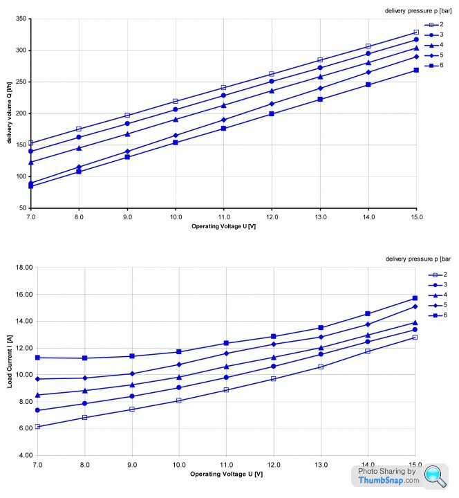
The difference between the effective "supply" voltage and the forward voltage must be the pumps' back EMF (the reverse voltage generated by the spinning magnets) so, back EMF = (7.0 - 2.4) = 4.6V
And as the back EMF is generated by the pump spinning, we know that this voltage is proportional to the speed of the pump (and hence its flow rate), where the max speed is clearly where the Back EMF = the supply voltage (in reality this can never quite occur due to frictional and copper losses in the rotor/windings) in this case the pump is going around about 33% of it's maximum speed (and the fuel mass supplied can easily be worked out from that speed)
I wrote to Bosch Motorsports Germany, and they apparently test the FP200 pumps (a.k.a "044") via linear regulation for the chart below. And as the back EMF is generated by the pump spinning, we know that this voltage is proportional to the speed of the pump (and hence its flow rate), where the max speed is clearly where the Back EMF = the supply voltage (in reality this can never quite occur due to frictional and copper losses in the rotor/windings) in this case the pump is going around about 33% of it's maximum speed (and the fuel mass supplied can easily be worked out from that speed)
Under PWM, how can current and voltage be controlled as separate inputs?
Also if BEMF is to be calculated via software, can PWM take the place of linear voltage control. Of course this leaves the aspect of controlling current for torque output.
Edited by Vee 12 on Sunday 12th February 21:27
An engine at idle may only require 0.1lt/min as opposed to 200lt/min. In a conventional system the pump would be still pumping 200lt/min, the engine using 0.1lt/min and 199.9lt/min being returned to th tank and therefore pumped unnecessarily.
A PWM controlled system can reduce the current so the pump only pumps only enough fuel to deal with the fuel required to run the engine and enough headroom for transient application of torque demand.
A PWM controlled system can reduce the current so the pump only pumps only enough fuel to deal with the fuel required to run the engine and enough headroom for transient application of torque demand.
stevesingo said:
An engine at idle may only require 0.1lt/min as opposed to 200lt/min. In a conventional system the pump would be still pumping 200lt/min, the engine using 0.1lt/min and 199.9lt/min being returned to th tank and therefore pumped unnecessarily.
A PWM controlled system can reduce the current so the pump only pumps only enough fuel to deal with the fuel required to run the engine and enough headroom for transient application of torque demand.
If you look at the chart above, we can see that it is possible to control impeller RPM by voltage. But PWM does not control pressure via current (from my understanding).A PWM controlled system can reduce the current so the pump only pumps only enough fuel to deal with the fuel required to run the engine and enough headroom for transient application of torque demand.
Also DSport Magazine here in the States showed how they got the test figures at RC Engineering via some power supply machine , but I have no idea what the PWM freq. was.
For a motor:
Current = Torque
Voltage = Speed + (current * resistance)
This is because the back emf of a motor is proportional to it's rotational speed and the forward emf proportional to the resistance of the windings multiplied by the current through the windings (V=IR)
For a positive displacement pump:
Pressure = torque (think of a piston in a cylinder, the harder you press on the piston the higher the output pressure capability)
Speed = displaced volume (more strokes per min = more flow)
So, to control fuel system pressure, you use a closed loop controller using measured motor current as the feedback.
And current is driven through the windings by the difference between the forward an back emfs.
For a fuel injection system, the flow is governed by engine consumption (and/or the setting of the mechanical pressure regulator).
If you control pump current to get to a target pressure, the system will adjust it's output voltage to get to that current target, the total output voltage and hence speed of the motor is automatically compensated for.
Consider a pump which is stopped, with no pressure on it.
We apply say 10% of the supply voltage. As the motor is stopped, there is no back emf, so all that applied voltage drives current through the windings and generates a large torque (because the series resistance of a motor winding is very small, typically ~100mOhm for a small DC motor). That torque causes the motor to start spinning, and fuel is pumped out of it.
If there is no restriction (pump just exiting into a bucket for example) then the motors speed increases rapidly until the back emf gets very close to the supply voltage, because very little torque is required to just move the fuel against a near zero pressure head. But if there is a restriction (ie a regulator or closed rail) as the pump spins, the output pressure climbs. As pressure climbs the pump torque increases as does the motor current. At some point, for a completely closed system, the pump will stop again, because it have reached it's limit torque (output pressure). But for an open system, or one with a relief regulator, once some pressure is reached, fuel will be allowed to spill back and hence pump current will stabilise.
If we now control to a fixed output voltage, if fuel demand falls, the pump slows (as pressure rises) and current increases. if demand rises, the pressure falls, current falls and the pump spins a bit faster. Here we control speed and current changes.
If we control to a fixed current, then the speed of the pump changes to reflect the load instead. And all we/the engine cares about is getting a nice stable fuel rail pressure. Hence we use a current/pressure control strategy rather than an output voltage control one.
In reality, if you control output voltage in respect of fuel pressure error, then the system sorts it's self out automatically.
I'd suggest reading up on PID and control basics for more info.
@Max_Torque
What type of hardware do you need for that kind of control for fixed current? Also is it possible to make a fuel pump controller than can also control output voltage along with current to have a 3D mapping for pressure/impeller speed/engine load dynamically? Can a Infineon BTN8982 half bridge work for this?
What type of hardware do you need for that kind of control for fixed current? Also is it possible to make a fuel pump controller than can also control output voltage along with current to have a 3D mapping for pressure/impeller speed/engine load dynamically? Can a Infineon BTN8982 half bridge work for this?
Ideally you need a system to measure output current, but in fact, if you just care about maintaining a target fuel rail pressure, you don't need that, you just need to measure actual rail pressure.
Infineon's high current half bridges are ideal, as they minimise conduction losses during the freewheeling (low) PWM period (synchronous rectification)
You find a Infineon half bridge in most OE fuel pump drivers
Infineon's high current half bridges are ideal, as they minimise conduction losses during the freewheeling (low) PWM period (synchronous rectification)
You find a Infineon half bridge in most OE fuel pump drivers
Max_Torque said:
Ideally you need a system to measure output current, but in fact, if you just care about maintaining a target fuel rail pressure, you don't need that, you just need to measure actual rail pressure.
Assuming that the pump's capabilities have been tested like in the Bosch chart above; Is there any aftermarket controller that allows you to command, "I want 2.0 Bar rail pressure and 50 LPH at 1200 rpm engine idle" and then command "At 7000 RPM & 2.0 Bar of boost, raise to 9.0 Bar rail pressure and 200 LPH". Does that type of system exist or am I missing some important information that makes this an impossibility? Gassing Station | Engines & Drivetrain | Top of Page | What's New | My Stuff